EP0624493B1 - Dachreling für Fahrzeuge - Google Patents
Dachreling für Fahrzeuge Download PDFInfo
- Publication number
- EP0624493B1 EP0624493B1 EP94106943A EP94106943A EP0624493B1 EP 0624493 B1 EP0624493 B1 EP 0624493B1 EP 94106943 A EP94106943 A EP 94106943A EP 94106943 A EP94106943 A EP 94106943A EP 0624493 B1 EP0624493 B1 EP 0624493B1
- Authority
- EP
- European Patent Office
- Prior art keywords
- support
- gallery
- side rail
- metal sleeve
- roof
- Prior art date
- Legal status (The legal status is an assumption and is not a legal conclusion. Google has not performed a legal analysis and makes no representation as to the accuracy of the status listed.)
- Expired - Lifetime
Links
- 229910052751 metal Inorganic materials 0.000 claims description 10
- 239000002184 metal Substances 0.000 claims description 10
- 230000001747 exhibiting effect Effects 0.000 claims 2
- 238000003780 insertion Methods 0.000 description 2
- 230000037431 insertion Effects 0.000 description 2
- 229910052782 aluminium Inorganic materials 0.000 description 1
- XAGFODPZIPBFFR-UHFFFAOYSA-N aluminium Chemical compound [Al] XAGFODPZIPBFFR-UHFFFAOYSA-N 0.000 description 1
- 238000002347 injection Methods 0.000 description 1
- 239000007924 injection Substances 0.000 description 1
- 238000009434 installation Methods 0.000 description 1
- 238000004519 manufacturing process Methods 0.000 description 1
Images

Classifications
-
- B—PERFORMING OPERATIONS; TRANSPORTING
- B60—VEHICLES IN GENERAL
- B60R—VEHICLES, VEHICLE FITTINGS, OR VEHICLE PARTS, NOT OTHERWISE PROVIDED FOR
- B60R9/00—Supplementary fittings on vehicle exterior for carrying loads, e.g. luggage, sports gear or the like
- B60R9/04—Carriers associated with vehicle roof
Definitions
- the invention relates to a roof rail for vehicles with a tubular gallery rod and support feet, which, if necessary, also support this at least at the end areas in the middle and are fixed to each of them by means of a threaded bolt and a nut screwed thereon.
- a roof rail for vehicles usually consists of two gallery bars, which extend approximately parallel to one another in the longitudinal direction of the vehicle and are attached to the longitudinal edges of the vehicle roof via supporting feet.
- Cross members for absorbing roof loads can be attached to the gallery bars.
- connection between a gallery bar and the support feet is made - cf. DE 36 26 926 A1 - conventionally in each case by means of an Allen screw which runs in a hollow support foot and is supported on the head side, penetrates an oblique opening in the gallery rod and can be screwed into a cylinder nut cut obliquely on the end face.
- the Allen screw is tightened from the open end of the support leg, the base of the gallery rod becomes between the oblique face of the support leg clamped frictionally.
- the known type of connection is reliable per se, but is unable to prevent the support feet from rotating in relation to the gallery bar in the pre-assembled state, which is desirable.
- a particular disadvantage of the known type of connection is the rather complex assembly, which requires a targeted insertion of the cylinder nut into the gallery rod opening and finding the threaded hole.
- the present invention is based on the object, in a roof railing of the type mentioned, to show a particularly simple to produce connection arrangement between a gallery bar and the support feet to be fixed thereon.
- the threaded bolt has a head in the manner of a hammer screw, which can be inserted through a slot opening in the gallery rod and axially fixed by a 90 ° rotation on the gallery rod, and in that two axial sections of the bolt shaft as a square for radially fixing the Threaded bolt are formed in the slot opening of the gallery rod and a square hole in the associated support foot.
- each support leg has a metal sleeve with a square hole and that the metal sleeve sits within a plastic cap forming the outer contour of the respective support leg.
- the metal sleeve secures the force of the roof load on a support structure of the vehicle roof and makes it possible to design the respective support barrel as a simple and inexpensive plastic injection molded part and thereby also to save weight.
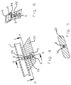
- FIG. 1 and 2 show a gallery rod 1, which can consist of an aluminum tube, and a support foot 2 attached to it at the end, via which the gallery rod 1 can be supported on a vehicle roof 3.
- the gallery rod 1 has a slot opening 4 on its side that comes to rest on the support foot.
- a T-slot that is open on the side is formed.
- the head 5 is dimensioned such that it can be inserted through the slot opening 4 into the gallery rod cavity and rotated therein.
- the head 5 of the threaded bolt 6 is shown in its secured position on the threaded rod 1 against being pulled out, in which it is rotated by 90 ° with respect to the insertion position.
- the threaded bolt 6 is used for the rotation-proof connection of gallery rod 1 and support leg 2. Therefore, it is with a first square 7, which directly adjoins the head 5, a second square 8, which is axially spaced from the first and with a screwed nut 9 carrying external thread formed on the free shaft area.
- the first square 7 engages in the slot opening 4 and thus fixes the threaded bolt 6 against rotation on the gallery rod 1.
- the second square 8 engages in a square hole 10 formed in the support barrel 2 and thus fixes the support base 2 against rotation on the threaded bolt 6 and thus also against rotation on the gallery rod 1.
- the support leg 2 consists of a metal sleeve 11 which has the inside of the second square 8 and a plastic cap 12 surrounding it, which is expediently designed as a plastic injection-molded part. It is advisable in the manufacture of the plastic cap 12 to encapsulate the metal sleeve 11 as an insert, although it is of course also possible to press the metal sleeve 11 into the plastic cap 12 subsequently or to clip the plastic cap 12 onto the metal sleeve 11.
- the support leg 2 is in turn supported by a receiving support 13 which is to be fastened to the roof structure, for example in a roof channel 14 formed here.
- the receiving support 13 is connected to the threaded bolt 6, supported on the lower end of the metal sleeve 11 and fixed on the threaded bolt 6 via the nut 9.
- FIGS. 4 to 6 show a support leg 22 serving as a central support for a gallery rod 1. Such a central support can be useful with longer gallery rods and / or with high load loads.
- the support foot 22 has a through hole 15 which is formed in the central region as a square hole 10 (cf. in particular FIG. 5).
- a threaded bolt 6, as has been described with reference to FIGS. 1 to 3, is used for fastening the support foot 22. Pushing through the bolt head 5 is made possible by a slot opening 44 which differs from the slot opening 4 only in that it is not designed to be open at the edge.
Landscapes
- Engineering & Computer Science (AREA)
- Mechanical Engineering (AREA)
- Fittings On The Vehicle Exterior For Carrying Loads, And Devices For Holding Or Mounting Articles (AREA)
- Body Structure For Vehicles (AREA)
Description
- Die Erfindung bezieht sich auf eine Dachreling für Fahrzeuge mit einem rohrförmigen Galeriestab und Stützfüßen, die diesen zumindest an den Endbereichen ggf. aber auch mittig abstützen und daran jeweils mittels eines Gewindebolzens und einer darauf geschraubten Mutter festgelegt sind.
- Eine Dachreling für Fahrzeuge besteht üblicherweise aus zwei sich in Fahrzeuglängsrichtung etwa parallel zueinander erstreckenden, an den Längsrändern des Fahrzeugdachs über Stützfüße befestigten Galeriestäben. An den Galeriestäben können Querträger zur Aufnahme von Dachlasten befestigt werden.
- Die Verbindung zwischen einem Galeriestab und den Stützfüßen erfolgt - vgl. DE 36 26 926 A1 - herkömmlicherweise jeweils mittels einer Inbusschraube, die in einem hohlen Stützfuß verläuft und kopfseitig abgestützt ist, einen schräg verlaufenden Durchbruch im Galeriestab durchsetzt und in eine stirnseitig schräg angeschnittene Zylindermutter einschraubbar ist. Beim Anziehen der Inbusschraube vom offenen Ende des Stützfußes her wird der Boden des Galeriestabs zwischen der schrägen Stirnfläche des Stützfußes reibschlüssig eingespannt. Die bekannte Verbindungsart ist an sich zuverlässig, vermag aber nicht ein Drehen der Stützfüße gegenüber dem Galeriestab im Vormontagezustand zu verhindern, was jedoch wünschenswert ist. Ein besonderer Nachteil bei der bekannten Verbindungsart besteht in der recht aufwendigen Montage, die ein gezieltes Einschieben der Zylindermutter in die Galeriestaböffnung und ein Auffinden der Gewindebohrung verlangt.
- Der vorliegenden Erfindung liegt nun die Aufgabe zugrunde, bei einer Dachreling der eingangs genannten Art eine besonders einfach herzustellende Verbindungsanordnung zwischen einem Galeriestab und den daran festzulegenden Stützfüßen aufzuzeigen.
- Diese Aufgabe wird erfindungsgemäß dadurch gelöst, daß der Gewindebolzen einen Kopf nach Art einer Hammerschraube aufweist, der durch eine Schlitzöffnung im Galeriestab steckbar und durch eine 90°-Drehbewegung am Galeriestab axial festlegbar ist und daß zwei axiale Teilbereiche des Bolzenschafts als Vierkant zur radialen Festlegung des Gewindebolzens in der Schlitzöffnung des Galeriestabs und einem Vierkantloch im zugehörigen Stützfuß ausgebildet sind.
- Durch diese erfindungsgemäßen Maßnahmen wird neben der Ausgleichsmöglichkeit von Längentoleranzen und einer Verdrehsicherung zwischen den Stützfüßen und dem Galeriestab insbesondere eine wesentliche Montageerleichterung erreicht. Der Gewindebolzen braucht lediglich mit seinem Kopf durch die Schlitzöffnung im Galeriestab gesteckt und hiernach gedreht werden und kann sodann den jeweiligen Stützfuß aufnehmen für dessen Festlegung am Galeriestab es dann lediglich noch des Aufschraubers der Mutter bedarf.
- Eine vorteilhafte Weiterbildung der Erfindung besteht darin, daß die in den Endbereichen des Galeriestabs auflageseitig eingebrachten Schlitzöffnungen randoffen auslaufen. Damit ergibt sich für die endseitigen Stützfüße die Möglichkeit, daran die Gewindebolzen vorzumontieren. Die Stützfüße können damit durch stirnseitiges Einschieben der Gewindebolzenköpfe in die Schlitzöffnungen am Galeriestab angebracht werden.
- Eine weitere Ausgestaltung der Erfindung sieht vor, daß jeder Stützfuß eine Metallhülse mit Vierkantloch aufweist und daß die Metallhülse innerhalb einer die Außenkontur des jeweiligen Stützfußes bildenden Kunststoffkappe sitzt. Die Metallhülse sichert die Krafteinleitung der Dachlast auf eine Tragestruktur des Fahrzeugdachs und ermöglicht es, den jeweiligen Stützfaß im übrigen als einfach und kostengünstig herzustellendes Kunststoff-Spritzgußteil auszubilden und dadurch auch Gewicht einzusparen.
- Ausführungsbeispiele der Erfindung werden nachfolgend anhand der Zeichnung näher erläutert. Es zeigen:
- Fig. 1
- den vertikalen Längsschnitt durch einen Galeriestabendbereich mit einem endseitigen Stützfuß,
- Fig. 2
- einen Schnitt, etwa folgend der Linie A-A in Fig. 1,
- Fig. 3
- einen Schnitt, etwa folgend der Linie B-B in Fig. 1,
- Fig. 4
- den vertikalen Längsschnitt durch einen Galeriestab in dessen Längsmitte mit einem Stützfuß,
- Fig. 5
- einen Schnitt, etwa folgend der Linie A-A in Fig. 4 und
- Fig. 6
- einen Schnitt, etwa folgend der Linie B-B in Fig. 4.
- Fig. 1 und 2 zeigen einen Galeriestab 1, der aus einem Aluminiumrohr bestehen kann sowie einen daran endseitig angebrachten Stützfuß 2, über den der Galeriestab 1 an einem Fahrzeugdach 3 abstützbar ist. Am freien Endbereich weist der Galeriestab 1 an seiner auf dem Stützfuß zur Auflage kommenden Seite eine Schlitzöffnung 4 auf. Hierdurch wird eine seitlich offene T-Nut gebildet. In diese T-Nut greift der Kopf 5 eines Gewindebolzens 6 ein, der nach Art einer Hammerschraube ausgebildet ist. Der Kopf 5 ist so bemessen, daß er durch die Schlitzöffnung 4 hindurch in den Galeriestabhohlraum einsteckbar und in diesem drehbar ist. In den Fig. 1 und 2 ist der Kopf 5 des Gewindebolzens 6 in seiner am Gewindestab 1 gegen Herausziehen gesicherten Position gezeigt, in der er gegenüber der Einsteckposition um 90° gedreht ist.
- Der Gewindebolzen 6 dient zur verdrehsicheren Verbindung von Galeriestab 1 und Stützfuß 2. Daher ist er mit einem ersten Vierkant 7, der sich unmittelbar an den Kopf 5 anschließt, einem zweiten Vierkant 8, der dem ersten axial beabstandet ist und mit einem eine aufgeschraubte Mutter 9 tragenden Außengewinde am freien Schaftbereich ausgebildet. Der erste Vierkant 7 greift in die Schlitzöffnung 4 ein und legt damit den Gewindebolzen 6 verdrehsicher am Galeriestab 1 fest. Der zweite Vierkant 8 greift in ein im Stützfaß 2 ausgebildetes Vierkantloch 10 ein und legt damit den Stützfuß 2 verdrehsicher am Gewindebolzen 6 und damit auch verdrehsicher am Galeriestab 1 fest.
- Im Ausführungsbeispiel nach den Fig. 1 bis 3 besteht der Stützfuß 2 aus einer im Inneren den zweiten Vierkant 8 aufweisenden Metallhülse 11 sowie einer diese umgebenden Kunststoffkappe 12, die zweckmäßigerweise als Kunststoff-Spritzgußteil ausgebildet ist. Dabei bietet es sich bei der Herstellung der Kunststoffkappe 12 an, die Metallhülse 11 als Einlegeteil zu umspritzen, obgleich es natürlich auch möglich ist, die Metallhülse 11 nachträglich in die Kunststoffkappe 12 einzupressen oder die Kunststoffkappe 12 auf die Metallhülse 11 zu klipsen.
- Der Stützfuß 2 wird seinerseits von einer Aufnahmestütze 13 getragen, die an der Dachkonstruktion, beispielsweise in einem hier ausgebildeten Dachkanal 14 zu befestigen ist. Die Aufnahmestütze 13 ist am Gewindebolzen 6 angeschlossen, am unteren Stirnende der Metallhülse 11 abgestützt und über die Mutter 9 am Gewindebolzen 6 festgelegt.
- Fig. 4 bis 6 zeigen einen als Mittelstütze dienenden Stützfuß 22 für einen Galeriestab 1. Eine solche Mittelstütze kann bei längeren Galeriestäben und/oder bei hoher Lastbeanspruchung nützlich sein. Der Stützfuß 22 weist eine Durchgangsbohrung 15 auf, die im mittleren Bereich als Vierkantloch 10 (vgl. insbesondere Fig. 5) ausgebildet ist. Für die Befestigung des Stützfußes 22 dient ein Gewindebolzen 6, wie er anhand der Fig. 1 bis 3 beschrieben worden ist. Das Durchstecken des Bolzenkopfs 5 wird durch eine Schlitzöffnung 44 ermöglicht, die sich von der Schlitzöffnung 4 lediglich dadurch unterscheidet, daß sie nicht randoffen ausgebildet ist.
Claims (3)
- Dachreling für Fahrzeuge mit einem rohrförmigen Galeriestab (1) und Stützfüßen (2, 22), die diesen zumindest an den Endbereichen ggf. aber auch mittig abstützen und daran jeweils mittels eines Gewindebolzens (6) und einer darauf geschraubten Mutter (9) festgelegt sind, dadurch gekennzeichnet, daß der Gewindebolzen (6) einen Kopf (5) nach Art einer Hammerschraube aufweist, der durch eine Schlitzöffnung (4, 44) im Galeriestab (1) steckbar und durch eine 90°-Drehbewegung am Galeriestab (1) axial festlegbar ist und daß zwei axiale Teilbereiche des Bolzenschafts als Vierkant (7, 8) zur radialen Festlegung des Gewindebolzens (6) in der Schlitzöffnung (4, 44) des Galeriestabs (1) und einem Vierkantloch (10) im zugehörigen Stützfuß (2) ausgebildet sind.
- Dachreling nach Anspruch 1, dadurch gekennzeichnet, daß die in den Endbereichen des Galeriestabs (1) auflageseitig eingebrachten Schlitzöffnungen (4) randoffen auslaufen.
- Dachreling nach Anspruch 1 oder 2, dadurch gekennzeichnet, daß jeder Stützfuß (2) eine Metallhülse (11) mit Vierkantloch (10) aufweist und daß die Metallhülse (11) innerhalb einer die Außenkontur des jeweiligen Stützfußes (2) bildenden Kunststoffkappe (12) sitzt.
Applications Claiming Priority (2)
| Application Number | Priority Date | Filing Date | Title |
|---|---|---|---|
| DE4315583 | 1993-05-11 | ||
| DE4315583A DE4315583A1 (de) | 1993-05-11 | 1993-05-11 | Dachreling für Fahrzeuge |
Publications (2)
| Publication Number | Publication Date |
|---|---|
| EP0624493A1 EP0624493A1 (de) | 1994-11-17 |
| EP0624493B1 true EP0624493B1 (de) | 1997-01-02 |
Family
ID=6487731
Family Applications (1)
| Application Number | Title | Priority Date | Filing Date |
|---|---|---|---|
| EP94106943A Expired - Lifetime EP0624493B1 (de) | 1993-05-11 | 1994-05-04 | Dachreling für Fahrzeuge |
Country Status (2)
| Country | Link |
|---|---|
| EP (1) | EP0624493B1 (de) |
| DE (2) | DE4315583A1 (de) |
Families Citing this family (1)
| Publication number | Priority date | Publication date | Assignee | Title |
|---|---|---|---|---|
| DE10346170A1 (de) * | 2003-10-01 | 2005-06-02 | Hagus C. Luchtenberg Gmbh & Co Kg | Fahrzeug-Dachreling |
Family Cites Families (3)
| Publication number | Priority date | Publication date | Assignee | Title |
|---|---|---|---|---|
| US3451602A (en) * | 1967-06-30 | 1969-06-24 | Bott John Anthony | Luggage rack |
| US3519178A (en) * | 1968-04-03 | 1970-07-07 | Helm Design & Mfg Inc | Automotive luggage rack air deflector |
| DE3626926A1 (de) * | 1986-08-08 | 1988-02-18 | Daimler Benz Ag | Befestigung von abdeckleisten auf kraftwagendaechern |
-
1993
- 1993-05-11 DE DE4315583A patent/DE4315583A1/de not_active Withdrawn
-
1994
- 1994-05-04 DE DE59401444T patent/DE59401444D1/de not_active Expired - Fee Related
- 1994-05-04 EP EP94106943A patent/EP0624493B1/de not_active Expired - Lifetime
Also Published As
| Publication number | Publication date |
|---|---|
| DE4315583A1 (de) | 1994-11-17 |
| EP0624493A1 (de) | 1994-11-17 |
| DE59401444D1 (de) | 1997-02-13 |
Similar Documents
| Publication | Publication Date | Title |
|---|---|---|
| EP0758728B1 (de) | Halteelement aus Kunststoff | |
| EP0353468B1 (de) | Verbindungselement | |
| EP0543046A1 (de) | Schraubeinheit | |
| DE102011051013A1 (de) | Vorrichtung zur Befestigung eines Anbauteils, zum Beispiel einer Reling, an einer Fahrzeugkarosserie | |
| EP1180193A1 (de) | Klemmbeschlag für die befestigung von glasscheiben | |
| EP0761986A2 (de) | Verbindungselement aus Kunststoff | |
| EP3586018B1 (de) | Befestigungsvorrichtung und befestigungsbaugruppe | |
| EP0657324B1 (de) | Dachreling für Fahrzeuge | |
| DE102019211757A1 (de) | Radialausgleichselement sowie Vorrichtung zum Ausgleichen von Toleranzen zwischen einem ersten Bauteil und einem zweiten Bauteil | |
| DE4301241C2 (de) | Längsverstellgetriebe, insbesondere Sitzverstellgetriebe in einem Kraftfahrzeug | |
| EP0950569B1 (de) | Befestigungsvorrichtung einer Fahrzeugdachreling | |
| EP0960983A2 (de) | Beplankungsvorrichtung einer Wandhalterung | |
| DE3928876A1 (de) | Einrichtung zum justieren eines stossfaengers an einem kraftfahrzeug | |
| EP0624493A1 (de) | Dachreling für Fahrzeuge | |
| DE19633203C2 (de) | Haltekammer zum lösbaren Verbinden von zumindest zwei Teilen | |
| EP0667463B1 (de) | Halteelement aus Kunststoff, insbesondere für Rohrleitungen | |
| DE10255774A1 (de) | Scheibenwischvorrichtung, insbesondere für ein Kraftfahrzeug | |
| WO2003021064A1 (de) | Klemmhalter für die befestigung von verbindungsstangen und/oder laufschienen mit daran geführten schiebeelementen | |
| EP1374725B1 (de) | Höhenverstellbare Stütze für Möbel | |
| CH680481A5 (de) | ||
| DE3913140C2 (de) | ||
| DE3722996C2 (de) | Türfeststeller für eine Fahrzeugtür | |
| EP1132260A2 (de) | Deformationselement für einen Gurthöhenversteller oder eine Haltestange einer Netztrennwand | |
| DE10106994C2 (de) | Deformationselement | |
| EP1264995A1 (de) | Vorrichtung zur Befestigung einer Bildröhre an einem Deckrahmen |
Legal Events
| Date | Code | Title | Description |
|---|---|---|---|
| PUAI | Public reference made under article 153(3) epc to a published international application that has entered the european phase |
Free format text: ORIGINAL CODE: 0009012 |
|
| AK | Designated contracting states |
Kind code of ref document: A1 Designated state(s): DE ES FR GB IT SE |
|
| RAP1 | Party data changed (applicant data changed or rights of an application transferred) |
Owner name: HAPPICH FAHRZEUG-DACHSYSTEME GMBH |
|
| 17P | Request for examination filed |
Effective date: 19941208 |
|
| GRAG | Despatch of communication of intention to grant |
Free format text: ORIGINAL CODE: EPIDOS AGRA |
|
| 17Q | First examination report despatched |
Effective date: 19960411 |
|
| GRAH | Despatch of communication of intention to grant a patent |
Free format text: ORIGINAL CODE: EPIDOS IGRA |
|
| GRAH | Despatch of communication of intention to grant a patent |
Free format text: ORIGINAL CODE: EPIDOS IGRA |
|
| GRAA | (expected) grant |
Free format text: ORIGINAL CODE: 0009210 |
|
| AK | Designated contracting states |
Kind code of ref document: B1 Designated state(s): DE ES FR GB IT SE |
|
| PG25 | Lapsed in a contracting state [announced via postgrant information from national office to epo] |
Ref country code: IT Free format text: LAPSE BECAUSE OF FAILURE TO SUBMIT A TRANSLATION OF THE DESCRIPTION OR TO PAY THE FEE WITHIN THE PRESCRIBED TIME-LIMIT;WARNING: LAPSES OF ITALIAN PATENTS WITH EFFECTIVE DATE BEFORE 2007 MAY HAVE OCCURRED AT ANY TIME BEFORE 2007. THE CORRECT EFFECTIVE DATE MAY BE DIFFERENT FROM THE ONE RECORDED. Effective date: 19970102 Ref country code: GB Effective date: 19970102 Ref country code: FR Effective date: 19970102 Ref country code: ES Free format text: THE PATENT HAS BEEN ANNULLED BY A DECISION OF A NATIONAL AUTHORITY Effective date: 19970102 |
|
| REF | Corresponds to: |
Ref document number: 59401444 Country of ref document: DE Date of ref document: 19970213 |
|
| EN | Fr: translation not filed | ||
| GBV | Gb: ep patent (uk) treated as always having been void in accordance with gb section 77(7)/1977 [no translation filed] |
Effective date: 19970102 |
|
| PLBE | No opposition filed within time limit |
Free format text: ORIGINAL CODE: 0009261 |
|
| STAA | Information on the status of an ep patent application or granted ep patent |
Free format text: STATUS: NO OPPOSITION FILED WITHIN TIME LIMIT |
|
| 26N | No opposition filed | ||
| PGFP | Annual fee paid to national office [announced via postgrant information from national office to epo] |
Ref country code: SE Payment date: 20020521 Year of fee payment: 9 |
|
| PGFP | Annual fee paid to national office [announced via postgrant information from national office to epo] |
Ref country code: DE Payment date: 20020523 Year of fee payment: 9 |
|
| PG25 | Lapsed in a contracting state [announced via postgrant information from national office to epo] |
Ref country code: SE Free format text: LAPSE BECAUSE OF NON-PAYMENT OF DUE FEES Effective date: 20030505 |
|
| PG25 | Lapsed in a contracting state [announced via postgrant information from national office to epo] |
Ref country code: DE Free format text: LAPSE BECAUSE OF NON-PAYMENT OF DUE FEES Effective date: 20031202 |
|
| EUG | Se: european patent has lapsed |