EP0624539A2 - Bobine rotative - Google Patents
Bobine rotative Download PDFInfo
- Publication number
- EP0624539A2 EP0624539A2 EP94303365A EP94303365A EP0624539A2 EP 0624539 A2 EP0624539 A2 EP 0624539A2 EP 94303365 A EP94303365 A EP 94303365A EP 94303365 A EP94303365 A EP 94303365A EP 0624539 A2 EP0624539 A2 EP 0624539A2
- Authority
- EP
- European Patent Office
- Prior art keywords
- core
- platform
- operably
- invention according
- platform means
- Prior art date
- Legal status (The legal status is an assumption and is not a legal conclusion. Google has not performed a legal analysis and makes no representation as to the accuracy of the status listed.)
- Granted
Links
Images
Classifications
-
- B—PERFORMING OPERATIONS; TRANSPORTING
- B65—CONVEYING; PACKING; STORING; HANDLING THIN OR FILAMENTARY MATERIAL
- B65H—HANDLING THIN OR FILAMENTARY MATERIAL, e.g. SHEETS, WEBS, CABLES
- B65H75/00—Storing webs, tapes, or filamentary material, e.g. on reels
- B65H75/02—Cores, formers, supports, or holders for coiled, wound, or folded material, e.g. reels, spindles, bobbins, cop tubes, cans, mandrels or chucks
- B65H75/04—Kinds or types
- B65H75/08—Kinds or types of circular or polygonal cross-section
- B65H75/14—Kinds or types of circular or polygonal cross-section with two end flanges
-
- B—PERFORMING OPERATIONS; TRANSPORTING
- B65—CONVEYING; PACKING; STORING; HANDLING THIN OR FILAMENTARY MATERIAL
- B65H—HANDLING THIN OR FILAMENTARY MATERIAL, e.g. SHEETS, WEBS, CABLES
- B65H75/00—Storing webs, tapes, or filamentary material, e.g. on reels
- B65H75/50—Methods of making reels, bobbins, cop tubes, or the like by working an unspecified material, or several materials
-
- B—PERFORMING OPERATIONS; TRANSPORTING
- B65—CONVEYING; PACKING; STORING; HANDLING THIN OR FILAMENTARY MATERIAL
- B65H—HANDLING THIN OR FILAMENTARY MATERIAL, e.g. SHEETS, WEBS, CABLES
- B65H2701/00—Handled material; Storage means
- B65H2701/30—Handled filamentary material
- B65H2701/31—Textiles threads or artificial strands of filaments
-
- B—PERFORMING OPERATIONS; TRANSPORTING
- B65—CONVEYING; PACKING; STORING; HANDLING THIN OR FILAMENTARY MATERIAL
- B65H—HANDLING THIN OR FILAMENTARY MATERIAL, e.g. SHEETS, WEBS, CABLES
- B65H2701/00—Handled material; Storage means
- B65H2701/50—Storage means for webs, tapes, or filamentary material
- B65H2701/51—Cores or reels characterised by the material
- B65H2701/511—Cores or reels characterised by the material essentially made of sheet material
- B65H2701/5112—Paper or plastic sheet material
Definitions
- the present invention relates to reels, and, more particularly, to a rotatable reel apparatus for use in association with an axle and the like, for operably winding, storing, transporting and unwinding various windable materials.
- first and second platform members include a plurality of core attachment flaps for operable securement to the inner peripheral surface of the core member, to, in turn, provide secured attachment of the respective platform member to the core member.
- the present invention comprises a rotatable reel apparatus for use in association with an axle and the like, for operably winding, storing, transporting and unwinding various windable materials such as rope, string, wire and film.
- Core means are provided for operably receiving and maintaining the windable material thereabout.
- the core means which may be constructed from a paper material, includes a top edge, a bottom edge opposite the top edge, an inner peripheral surface extending between the top and bottom edges, an interior region adjacently formed within the inner peripheral surface, and an outer peripheral surface for operable contact with at least a portion of the windable material upon the receipt and maintenance thereof.
- First and second platform means which may have a substantially circular configuration, are operably attached adjacent to a corresponding one of the top and bottom edges of the core means so as to sandwich the core means, and in turn, the windable material positioned about the core means, therebetween.
- Each of the first and second platform means are constructed from a corrugated paper material having an interior surface, an exterior surface opposite the interior surface, and an outer periphery greater than the outer peripheral surface of the core means.
- Each of the first and second platform means include a plurality of operably positioned core attachment flap means which are integrally formed in, and inwardly folded from, each of the first and second platform means. Accordingly, the inwardly folded orientation of the flap means enable the first and second platform means to be operably secured to at least a portion of at least one of the inner and outer peripheral surfaces of the core means.
- the plurality of integrally formed and inwardly folded core attachment flap means result in a plurality of spaced apart apertures in the first and second platform means.
- Each of such spaced apart apertures include a proximal edge adjacent at least one of the inner and outer peripheral surfaces of the core means, and a distal edge.
- the distal edges serve to collectively define the outer periphery of a the spindle region which is substantially concentrically oriented with respect to the corresponding first and second platform means.
- Spindle attachment means are operably positioned within each of the spindle regions of each of the first and second platform means at the centers thereof respectively.
- the spindle attachment means which may comprise a substantially circular aperture, of each of the spindle regions are operably aligned with each other and positioned adjacent the interior region of the core means so as to facilitate operable cooperation with, and rotation about, the axle.
- the rotatable reel apparatus further includes securement means operably associated with at least one of the inner and outer peripheral surfaces of the core means and each of the core attachment flap means of the first and second platform means.
- securement means serve to operably secure each of the core attachment flap means, and, in turn, the first and second platform means, to the core means.
- the securement means may additionally be operably associated with the top and bottom edges of the core means and a corresponding portion of the interior surfaces of the first and second platform means so as to provide enhanced securement of the first and second platform means to the core means. It is contemplated that the securement means comprise conventional adhesive, such as glue.
- At least one of the first and second platform means further includes strengthening means for increasing the structural rigidity and compressibility of a corresponding one of the first and second platform means.
- the strengthening means may comprise at least one of the first and second platform means having two or more corrugated layers of paper material.
- each of the layers of the corrugated paper material of the first and second platform means be constructed from a liner board corrugated medium having an inner liner board layer, an outer liner board layer and a fluted corrugated medium material adhesively sandwiched therebetween. Accordingly, when multiple layers of such corrugated medium are used for purposes of strengthening the structural integrity of the first and second platform means, each of such layers used may have their respective fluted portions in substantially parallel alignment with each other, or, alternatively, such fluted portions of each layer may be operably positioned in non-parallel alignment with each other.
- the rotatable reel apparatus further includes at least one material engagement slot means integrally formed in at least one of the first and second platform means for operably receiving and releasably maintaining a lead portion of the windable material upon initial winding of same about the outer peripheral surface of the core means.
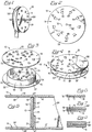
- Rotatable reel apparatus 10 is shown in Figs. 1 through 3 as including core means 12 (Fig. 3), first platform means 14 and second platform means 16 (Fig. 1 and Fig. 3).
- Core means 12 which is operably sandwiched between first and second platform means 14 and 16, respectively, is shown in Fig. 3, as including top edge 20, bottom edge 21 (Fig. 5), inner peripheral surface 23, interior region 24 and outer peripheral surface 26.
- First and second platform means 14 and 16, respectively, are shown in Fig. 4, as each including an interior surface 28, 28' (Fig. 5), an exterior surface 29, 29', an outer periphery 30, 30', a plurality of core attachment flap means, such as core attachment flap means 31 through 34 of first platform means 14, and core attachment flap means 36 through 39 of second platform means 16 (Fig. 3), a corresponding number of spaced apart apertures, such as spaced apart apertures 41 through 45 of first platform means 14 (Fig. 3), a spindle region 18, 18', spindle attachment means 50, 50' and material engagement slot means 52, 52'.
- Material engagement slot means 52, 52' which are shown as having rectilinear configurations, extend all the way through the respective first and second platform means, and serve to operably receive and releasably maintain a lead portion of windable material, such as windable material 100 (Fig. 1) which is to be operably wound around outer peripheral surface 26 of core means 12.
- First and second platform means 14 and 16 are constructed from a corrugated paper material, such as a liner board corrugated medium, as shown in Figs. 6 through 8, of the type comprising an inner liner board layer 70, an outer liner board layer 71 and a fluted corrugated material 72 sandwiched therebetween.
- a corrugated paper material such as a liner board corrugated medium, as shown in Figs. 6 through 8
- the first and second platform means be constructed from multiple layers of such corrugated paper material, as shown in Figs. 4, 7 and 8.
- such an additional layer 80 can be constructed without apertures so that when it is operably attached to exterior surface, such as exterior surface 29, of platform means, such as platform means 14, it will completely cover each of the spaced apart apertures of the underlying layer -- while maintaining operable exposure, and accordingly access to, each respective spindle attachment means 50, 50' and material engagement slots 52, 52' (Fig. 3) of first and second platform means 14 and 16, respectively.
- each of the layers which comprise the platform means are shown as comprising liner board corrugated medium, it is additionally contemplated that other types of conventional corrugated medium be used -- including such medium wherein the inner and outer liner board may be fabricated from Kraft paper and/or grease proof paper, among others.
- Spaced apart apertures such as spaced apart apertures 41 through 45 of first platform means 14 (Fig. 3), each include a proximal edge, such as proximal edges 56 through 59 (Fig. 2), and a corresponding number of distal edges, such as distal edges 61 through 64 (Fig. 3), respectively.
- each of the proximal edges of the spaced apart apertures are operably positioned adjacent inner peripheral surface 23 (Fig. 3) of core means 12, and, each of the distal edges of the spaced apart apertures are operably positioned adjacent interior region 24 of the core means.
- the core flaps may be attached to the inner and outer, or solely the outer, peripheral surface of core means 12. In either embodiment, each of such distal edges collectively serve to define the outer periphery of the spindle regions, such as spindle region 18, of a respective platform means.
- Core attachment flap means such as core attachment flap means 31 through 34 of first platform means 14, and, core attachment flap means 36 through 39 of second platform means 16, are shown in Fig. 3, as being integrally dependent from a corresponding proximal edge of a respective one of the spaced apart apertures.
- Each of such core attachment flap means are inwardly folded toward and into operable contact with either inner peripheral surface 23 or outer peripheral surface 26 of core means 12 for purposes of providing secured attachment of the corrugated paper platform means thereto.
- Fig. 3 Core attachment flap means, such as core attachment flap means 31 through 34 of first platform means 14, and, core attachment flap means 36 through 39 of second platform means 16, are shown in Fig. 3, as being integrally dependent from a corresponding proximal edge of a respective one of the spaced apart apertures.
- Each of such core attachment flap means are inwardly folded toward and into operable contact with either inner peripheral surface 23 or outer peripheral surface 26 of core means 12 for purposes of providing secured attachment of the corrugated paper platform means thereto.
- securement means 67 such as adhesive
- securement means 67 can comprise conventional adhesive, such as glue, it is also contemplated that other types of conventional means to secure such corrugated paper attachment flap means to the core means -- such as staples and/or rivets -- be used.
- each of the core attachment flap means have a trapezoid-shaped configuration which substantially conforms to the shape of the spaced apart apertures from which they depend -- although other configurations, besides trapezoidal, are also contemplated.
- the preferred embodiment has a corresponding number of core attachment flaps and spaced apart apertures wherein each of the spaced apart apertures, such as aperture 41 (Fig. 5) in first platform means 14, are in substantial alignment with the spaced apart apertures, such as aperture 41 (Fig. 5) in second platform means 16.
- first and second platform means 14 and 16, respectively, to core means 12 is accomplished through operable cooperation between the core attachment flap means and inner peripheral surface 23 of the core means
- additional securement is also contemplated so as to reduce the likelihood of inadvertently severing one, or both, of the first and second platform means from the core means.
- additional securement can be accomplished by operably applying adhesive 67, or the like, between interior surfaces 28 and 28' of first and second platform means 14 and 16, respectively, and the corresponding top edge 20 and bottom edge 21 of core means 12. It is contemplated that such additional securement consist of operably applying adhesive either to the entirety of the top and bottom edges of the core means, or merely at various spaced apart, spotted regions.
- Spindle attachment means 50, 50' are shown in Fig. 3 as comprising substantially circular apertures concentrically positioned within a respective spindle region 18, 18' of first and second platform means 14 and 16.
- circular apertures 50, 50' are operably aligned with each other and positioned adjacent interior region 24 of core means 12, so as to facilitate operable cooperation with, and rotation about, axle 101, as shown in Fig. 1.
- the spindle attachment means, as well the core means and the first and second platform means are each shown as having a substantially circular configuration, other configurations, such as hexagonal, octagonal or even rectangular, among others, are also contemplated.
Landscapes
- Storage Of Web-Like Or Filamentary Materials (AREA)
- Unwinding Of Filamentary Materials (AREA)
- Storing, Repeated Paying-Out, And Re-Storing Of Elongated Articles (AREA)
- Replacement Of Web Rolls (AREA)
- Valve Device For Special Equipments (AREA)
- Massaging Devices (AREA)
- Switches With Compound Operations (AREA)
- Liquid Crystal (AREA)
Applications Claiming Priority (2)
| Application Number | Priority Date | Filing Date | Title |
|---|---|---|---|
| US60583 | 1993-05-12 | ||
| US08/060,583 US5509620A (en) | 1993-05-12 | 1993-05-12 | Rotatable reel apparatus |
Publications (3)
| Publication Number | Publication Date |
|---|---|
| EP0624539A2 true EP0624539A2 (fr) | 1994-11-17 |
| EP0624539A3 EP0624539A3 (fr) | 1995-02-22 |
| EP0624539B1 EP0624539B1 (fr) | 1997-01-15 |
Family
ID=22030426
Family Applications (1)
| Application Number | Title | Priority Date | Filing Date |
|---|---|---|---|
| EP94303365A Expired - Lifetime EP0624539B1 (fr) | 1993-05-12 | 1994-05-10 | Bobine rotative |
Country Status (7)
| Country | Link |
|---|---|
| US (1) | US5509620A (fr) |
| EP (1) | EP0624539B1 (fr) |
| JP (1) | JPH0769537A (fr) |
| AT (1) | ATE147705T1 (fr) |
| AU (2) | AU6304594A (fr) |
| CA (1) | CA2123246A1 (fr) |
| DE (1) | DE69401456T2 (fr) |
Families Citing this family (14)
| Publication number | Priority date | Publication date | Assignee | Title |
|---|---|---|---|---|
| US5791590A (en) * | 1997-02-18 | 1998-08-11 | Zuk; Benjamin R. | Universal reel |
| MX9703997A (es) * | 1997-05-30 | 1998-11-30 | Servicios Condumex Sa | Sistema de embalaje y estibado de conductores electricos automotrices. |
| US6752350B2 (en) | 1999-05-27 | 2004-06-22 | Stone Container Corporation | Composite reel apparatus |
| US6712309B1 (en) * | 2000-10-20 | 2004-03-30 | Ernest Paper Products Inc. | Method and means for packaging draperies for purposes of storage or transportation |
| US6612247B1 (en) | 2002-09-11 | 2003-09-02 | St. Marys Box Co. Inc. | Corrugated shipping pallet |
| US20060000732A1 (en) * | 2004-07-01 | 2006-01-05 | Wayne Wei Shen | Ribbon packaging device |
| JP2007052831A (ja) * | 2005-08-16 | 2007-03-01 | Fujifilm Holdings Corp | リール及び記録テープカートリッジ |
| US8766141B2 (en) * | 2006-07-21 | 2014-07-01 | Illinois Tool Works Inc. | Welding system having a wire-specific interface |
| CA2701532C (fr) * | 2007-10-03 | 2017-04-18 | Vail Industries Inc. | Touret de papier ondule |
| WO2012018787A2 (fr) * | 2010-08-02 | 2012-02-09 | Adc Telecommunications, Inc. | Ensemble bobine de câble |
| US9556000B2 (en) | 2014-04-29 | 2017-01-31 | Inteplast Group Corporation | Reel assembly |
| US10526106B2 (en) | 2016-12-30 | 2020-01-07 | Inteplast Group Corporation | Bulk bin, bulk bin sleeve pack, and related method |
| US10577230B1 (en) | 2018-10-22 | 2020-03-03 | Gary Shelton | Winch device |
| US11993451B2 (en) | 2020-07-30 | 2024-05-28 | Inteplast Group Corporation | Bulk bin, bulk bin sleeve pack, and related method |
Family Cites Families (19)
| Publication number | Priority date | Publication date | Assignee | Title |
|---|---|---|---|---|
| US710774A (en) * | 1901-03-05 | 1902-10-07 | Henry W Hales | Spool for photographic films. |
| US1393420A (en) * | 1921-01-05 | 1921-10-11 | Ash Thomas | Film-reel |
| US1466157A (en) * | 1922-03-01 | 1923-08-28 | Charles E Byrne | Spool for photographic films and the like |
| US1560120A (en) * | 1923-01-12 | 1925-11-03 | Earl S Teed | Spool construction |
| US1985760A (en) * | 1931-02-26 | 1934-12-25 | Baxenden Thomas George | Spool and method for its manufacture |
| US2211461A (en) * | 1939-08-31 | 1940-08-13 | Gross Charles | Narrow fabric holder |
| FR866490A (fr) * | 1940-04-12 | 1941-08-14 | Perfectionnements aux bobines métalliques pour pellicules photographiques et nouvelles bobines faisant application de ces perfectionnements | |
| US3063652A (en) * | 1956-07-05 | 1962-11-13 | Joseph A Bell | Reel construction for motion picture film and for magnetic tape and the like |
| US3093343A (en) * | 1958-02-27 | 1963-06-11 | West Virginia Pulp & Paper Com | Paperboard reel |
| US3059763A (en) * | 1958-03-17 | 1962-10-23 | Stephen L Eifrid | Reel assembly and method of constructing same |
| US3145823A (en) * | 1962-11-13 | 1964-08-25 | Erdman O Spradlin | Typewriter ribbon spool construction |
| US3284022A (en) * | 1963-11-26 | 1966-11-08 | Stephen L Eifrid | Collapsible reels |
| US3342435A (en) * | 1966-04-11 | 1967-09-19 | Data Packaging Corp | Reel with tape guide |
| US3389872A (en) * | 1967-01-25 | 1968-06-25 | George F. Lyman | Reel |
| US3454155A (en) * | 1968-02-23 | 1969-07-08 | Badger Plug Co | Core assembly with positioning pad |
| US3958775A (en) * | 1975-02-06 | 1976-05-25 | Kessler Products Co., Inc. | Interlocking cardboard spool assembly |
| US4240593A (en) * | 1979-11-05 | 1980-12-23 | Jiffy Manufacturing Company, Inc. | Reel having honeycomb core |
| US4487136A (en) * | 1982-12-27 | 1984-12-11 | Packaging Materials Corporation | Pallet leg for a corrugated cardboard pallet |
| US4995512A (en) * | 1990-06-05 | 1991-02-26 | Shippers Paper Products Company | Interior core protector |
-
1993
- 1993-05-12 US US08/060,583 patent/US5509620A/en not_active Expired - Lifetime
-
1994
- 1994-05-10 EP EP94303365A patent/EP0624539B1/fr not_active Expired - Lifetime
- 1994-05-10 CA CA002123246A patent/CA2123246A1/fr not_active Abandoned
- 1994-05-10 DE DE69401456T patent/DE69401456T2/de not_active Expired - Fee Related
- 1994-05-10 JP JP6119694A patent/JPH0769537A/ja active Pending
- 1994-05-10 AT AT94303365T patent/ATE147705T1/de not_active IP Right Cessation
- 1994-05-11 AU AU63045/94A patent/AU6304594A/en not_active Abandoned
-
1998
- 1998-02-16 AU AU54659/98A patent/AU5465998A/en not_active Abandoned
Also Published As
| Publication number | Publication date |
|---|---|
| CA2123246A1 (fr) | 1994-11-13 |
| DE69401456T2 (de) | 1997-08-21 |
| EP0624539B1 (fr) | 1997-01-15 |
| US5509620A (en) | 1996-04-23 |
| DE69401456D1 (de) | 1997-02-27 |
| AU6304594A (en) | 1994-11-17 |
| AU5465998A (en) | 1998-05-28 |
| JPH0769537A (ja) | 1995-03-14 |
| ATE147705T1 (de) | 1997-02-15 |
| EP0624539A3 (fr) | 1995-02-22 |
Similar Documents
| Publication | Publication Date | Title |
|---|---|---|
| US5509620A (en) | Rotatable reel apparatus | |
| US3876073A (en) | Heavy duty paper board reel | |
| US5465672A (en) | Wrapped deck pallet | |
| ATE186266T1 (de) | Verpackung aus schichtstoffmaterial | |
| NZ280598A (en) | Package for spool of cable: spool mounted on end plates which are positioned in box | |
| US4778075A (en) | Rib form for tank ribs | |
| JPS5844078U (ja) | 虫取紙 | |
| US4861357A (en) | Vacuum cleaner bag collar | |
| US4413734A (en) | Multiple component film package | |
| US4830271A (en) | End closure for a multi-walled container | |
| CA2701532A1 (fr) | Touret de papier ondule | |
| US4435479A (en) | Packaging for fragile, heavy and/or deformable products | |
| US4240593A (en) | Reel having honeycomb core | |
| US3838602A (en) | Reinforced reel | |
| US4019692A (en) | Reinforced reel | |
| EP0411045B1 (fr) | Conteneur d'emballage | |
| US3971527A (en) | Yarn reel | |
| US6092659A (en) | Restricted orientation shipping carton | |
| US6527168B1 (en) | Stackable and readily separable carton blank with ease of assembly features | |
| JPH0240053Y2 (fr) | ||
| EP1630109A1 (fr) | Boîte pour rouleaux de matériau flexible | |
| US3508698A (en) | Combination shipping and storage container | |
| DE4025906A1 (de) | Sammelverpackung fuer auf kerne gewickelte magnetbaender | |
| EP0706956A2 (fr) | Ensemble d'emballage et méthode pour sa fabrication | |
| JPH0330556Y2 (fr) |
Legal Events
| Date | Code | Title | Description |
|---|---|---|---|
| PUAI | Public reference made under article 153(3) epc to a published international application that has entered the european phase |
Free format text: ORIGINAL CODE: 0009012 |
|
| AK | Designated contracting states |
Kind code of ref document: A2 Designated state(s): AT DE FR GB IT |
|
| PUAL | Search report despatched |
Free format text: ORIGINAL CODE: 0009013 |
|
| AK | Designated contracting states |
Kind code of ref document: A3 Designated state(s): AT DE FR GB IT |
|
| 17P | Request for examination filed |
Effective date: 19950320 |
|
| 17Q | First examination report despatched |
Effective date: 19950427 |
|
| GRAG | Despatch of communication of intention to grant |
Free format text: ORIGINAL CODE: EPIDOS AGRA |
|
| GRAH | Despatch of communication of intention to grant a patent |
Free format text: ORIGINAL CODE: EPIDOS IGRA |
|
| GRAH | Despatch of communication of intention to grant a patent |
Free format text: ORIGINAL CODE: EPIDOS IGRA |
|
| GRAA | (expected) grant |
Free format text: ORIGINAL CODE: 0009210 |
|
| AK | Designated contracting states |
Kind code of ref document: B1 Designated state(s): AT DE FR GB IT |
|
| REF | Corresponds to: |
Ref document number: 147705 Country of ref document: AT Date of ref document: 19970215 Kind code of ref document: T |
|
| REF | Corresponds to: |
Ref document number: 69401456 Country of ref document: DE Date of ref document: 19970227 |
|
| ITF | It: translation for a ep patent filed | ||
| ET | Fr: translation filed | ||
| PLBE | No opposition filed within time limit |
Free format text: ORIGINAL CODE: 0009261 |
|
| STAA | Information on the status of an ep patent application or granted ep patent |
Free format text: STATUS: NO OPPOSITION FILED WITHIN TIME LIMIT |
|
| 26N | No opposition filed | ||
| PGFP | Annual fee paid to national office [announced via postgrant information from national office to epo] |
Ref country code: GB Payment date: 19980403 Year of fee payment: 5 |
|
| PGFP | Annual fee paid to national office [announced via postgrant information from national office to epo] |
Ref country code: AT Payment date: 19980408 Year of fee payment: 5 |
|
| PGFP | Annual fee paid to national office [announced via postgrant information from national office to epo] |
Ref country code: FR Payment date: 19980508 Year of fee payment: 5 |
|
| PGFP | Annual fee paid to national office [announced via postgrant information from national office to epo] |
Ref country code: DE Payment date: 19980529 Year of fee payment: 5 |
|
| PG25 | Lapsed in a contracting state [announced via postgrant information from national office to epo] |
Ref country code: GB Free format text: LAPSE BECAUSE OF NON-PAYMENT OF DUE FEES Effective date: 19990510 Ref country code: AT Free format text: LAPSE BECAUSE OF NON-PAYMENT OF DUE FEES Effective date: 19990510 |
|
| GBPC | Gb: european patent ceased through non-payment of renewal fee |
Effective date: 19990510 |
|
| PG25 | Lapsed in a contracting state [announced via postgrant information from national office to epo] |
Ref country code: FR Free format text: LAPSE BECAUSE OF NON-PAYMENT OF DUE FEES Effective date: 20000131 |
|
| PG25 | Lapsed in a contracting state [announced via postgrant information from national office to epo] |
Ref country code: DE Free format text: LAPSE BECAUSE OF NON-PAYMENT OF DUE FEES Effective date: 20000301 |
|
| REG | Reference to a national code |
Ref country code: FR Ref legal event code: ST |
|
| PG25 | Lapsed in a contracting state [announced via postgrant information from national office to epo] |
Ref country code: IT Free format text: LAPSE BECAUSE OF NON-PAYMENT OF DUE FEES;WARNING: LAPSES OF ITALIAN PATENTS WITH EFFECTIVE DATE BEFORE 2007 MAY HAVE OCCURRED AT ANY TIME BEFORE 2007. THE CORRECT EFFECTIVE DATE MAY BE DIFFERENT FROM THE ONE RECORDED. Effective date: 20050510 |