EP0624691A2 - Bürstenausleger für Tunnelwaschfahrzeuge - Google Patents
Bürstenausleger für Tunnelwaschfahrzeuge Download PDFInfo
- Publication number
- EP0624691A2 EP0624691A2 EP94890083A EP94890083A EP0624691A2 EP 0624691 A2 EP0624691 A2 EP 0624691A2 EP 94890083 A EP94890083 A EP 94890083A EP 94890083 A EP94890083 A EP 94890083A EP 0624691 A2 EP0624691 A2 EP 0624691A2
- Authority
- EP
- European Patent Office
- Prior art keywords
- brush
- boom
- apron
- partial cover
- broom
- Prior art date
- Legal status (The legal status is an assumption and is not a legal conclusion. Google has not performed a legal analysis and makes no representation as to the accuracy of the status listed.)
- Granted
Links
Images
Classifications
-
- E—FIXED CONSTRUCTIONS
- E01—CONSTRUCTION OF ROADS, RAILWAYS, OR BRIDGES
- E01H—STREET CLEANING; CLEANING OF PERMANENT WAYS; CLEANING BEACHES; DISPERSING OR PREVENTING FOG IN GENERAL CLEANING STREET OR RAILWAY FURNITURE OR TUNNEL WALLS
- E01H1/00—Removing undesirable matter from roads or like surfaces, with or without moistening of the surface
- E01H1/005—Mobile installations, particularly for upkeeping in situ road or railway furniture, for instance road barricades, traffic signs; Mobile installations particularly for upkeeping tunnel walls
-
- B—PERFORMING OPERATIONS; TRANSPORTING
- B08—CLEANING
- B08B—CLEANING IN GENERAL; PREVENTION OF FOULING IN GENERAL
- B08B15/00—Preventing escape of dirt or fumes from the area where they are produced; Collecting or removing dirt or fumes from that area
- B08B15/04—Preventing escape of dirt or fumes from the area where they are produced; Collecting or removing dirt or fumes from that area from a small area, e.g. a tool
Definitions
- the invention relates to a brush boom for tunnel washing vehicles, with which a rotatably drivable roller brush can be adjusted to its respective work area, the brush on the boom also having spray or spray nozzles for washing and rinsing liquid which can be adjusted to the work area being arranged upstream and downstream and the boom being one Brush from the boom to its apron-like, apron-like, curved partial cover is provided for the back of the brush.
- Such a brush arm is such. B. from AT-PS 344 232 and AT-PS 380 711 known.
- By adjusting the height of the boom by rotating the brush around an axis that is normal to its longitudinal axis and finally by pivoting the brush, it is possible to adjust the brush to different working areas on the tunnel wall and also to select a width of the working area by the mentioned pivoting that is less than the brush length.
- Two or more brush arms can also be provided on the washing vehicle, which clean adjacent strips of the tunnel wall.
- the aforementioned, apron-like partial cover for the rear of the brush is provided in order to reduce the formation of spray during brush operation and in particular in order to prevent spraying or spraying of washing and rinsing liquid in the direction of the driver of the tunnel washing vehicle or an operator for the brush boom (s) and to give these people the best possible view of the working area of the brush.
- the apron-like partial cover is normally only applied over about a quarter of the brush circumference in order to enable all brush settings and, in particular in extreme positions of the brush, the cover to be approached to obstacles present in the tunnel, e.g. B. to prevent traffic signs, air inlets and outlets, etc.
- Spray and spray nozzles are usually mounted on these apron-like partial covers or on separate brackets. This results in a relatively complex overall construction for the tunnel washing vehicle, and it is often not possible to adequately avoid splash water separations and spray mist formation behind the tunnel washing vehicle.
- the object of the invention is to provide a brush arm of the type mentioned, which largely prevents spray water deposits or spray mist formation with a simple structure and which at least simplifies and optimizes rinsing.
- a second apron part is provided, which can be extended via a drive device from a rest position overlapping the partial cover via selectable intermediate layers to an end position surrounding the brush together with the partial cover by at least 170 °, preferably spraying or Spray nozzles for the rinsing liquid are attached to this second apron part in order to achieve an optimal cleaning effect.
- the optimally possible cover for preventing the discharge of spray water and the formation of spray mist can be set in every operating position of the brush, whereby an optimal cleaning effect of the spray nozzles is also achieved. It is still possible to pull back the apron part if obstacles occur, that he no longer runs into the obstacle.
- the corresponding control for the drive device can be combined with a control device for pivoting the boom, with the aid of which the obstacles mentioned can be avoided. Retraction of the second apron part is also necessary if, with the help of the boom, wall parts standing transversely to the remaining tunnel wall, e.g. B. paragraphs in the tunnel height or straight walls to be washed.
- the spray or spray nozzles are attached in the form of a nozzle bar to the front edge of the second apron part.
- the partial cover and the second apron part are attached to their brackets in a transport position so that they take up as little space as possible during transport.
- a brush arm 1 can be pivoted gimbally about a vertical and transverse axis on a tunnel washing vehicle and is adjustably supported in any pivoting position.
- a brush holder 2 At the end of the arm 1 there is a brush holder 2 which can be rotated about its longitudinal axis with respect to the arm, preferably a transverse axis 3 of the brush holder 2 also from it to the arm 1 normal position using actuators with their axis of rotation inclined to the boom.
- a roller brush 4 is attached to the brush holder so that it can be driven in rotation by means of an oil motor 5.
- the axis 3 can also be designed as a purely transverse axis and the brush 4 can be inclined with its axis of rotation with respect to the boom 1 via actuators.
- An apron-like partial cover 7 is attached to the brush holder 2 at 6.
- the construction described so far is state of the art.
- a holder 8 for a nozzle bar 9 is attached to the brush holder, via whose individual nozzles 10 a washing liquid can be sprayed onto the brush or directly onto the tunnel wall.
- the tunnel washing vehicle travels to the left and the brush 4 can preferably be driven at a variable speed in a counterclockwise direction of rotation.
- a second apron part 11 which is held on pivot arms 12 attached outside the partial cover 7 or guided through slots in the cover 7, and via hydraulic cylinder-piston units 13 from the illustrated part 7, which act on the arms 12 overlapping rest position while reducing the overlap is adjustable until in the end position together with the cover 7 it encloses the brush 4 by at least 170 or 180 °.
- a nozzle bar 15 with spray nozzles 16 is attached, through which a washing liquid is sprayed out.
- Supply lines 17, 18 for the nozzles 10, 16 have been indicated by dash-dotted lines.
- the partial cover 7 can be mounted on the swivel arms 12 and the apron 7 at its fastening point 6 in a transportable position.
Landscapes
- Engineering & Computer Science (AREA)
- Architecture (AREA)
- Civil Engineering (AREA)
- Structural Engineering (AREA)
- Vehicle Cleaning, Maintenance, Repair, Refitting, And Outriggers (AREA)
Abstract
Description
- Die Erfindung betrifft einen Bürstenausleger für Tunnelwaschfahrzeuge, mit dem eine drehend antreibbare Walzenbürste auf ihren jeweiligen Arbeitsbereich einstellbar ist, wobei der Bürste am Ausleger ebenfalls auf den Arbeitsbereich einstellbare Spritz- oder Sprühdüsen für Wasch- und Spülflüssigkeit vor- und nachgeordnet sind und am Ausleger eine die Bürste vom Ausleger bis über ihre Lagerstelle umschließende, schürzenartige, gewölbte Teilabdeckung für die Bürstenrückseite vorgesehen ist.
- Ein derartiger Bürstenausleger ist z. B. aus der AT-PS 344 232 und der AT-PS 380 711 bekannt. Durch Einstellung der Höhe des Auslegers, durch Verdrehen der Bürste um eine normal zu ihrer Längsachse verlaufende Achse und schließlich durch Verschwenken der Bürste wird es möglich, die Bürste auf verschiedene Arbeitsbereiche an der Tunnelwandung einzustellen und auch durch die erwähnte Verschwenkung eine Breite des Arbeitsbereiches zu wählen, die kleiner ist als die Bürstenlänge. Dabei können am Waschfahrzeug auch zwei oder mehrere Bürstenausleger vorgesehen werden, die benachbarte Streifen der Tunnelwandung reinigen.
- Die erwähnte, schürzenartige Teilabdeckung für die Bürstenrückseite wird vorgesehen, um die Sprühnebelbildung beim Bürstenbetrieb zu verringern und insbesondere um ein Abspritzen oder Absprühen von Wasch- und Spülflüssigkeit in Richtung auf den Fahrer des Tunnelwaschfahrzeuges bzw. eine Bedienungsperson für den bzw. die Bürstenausleger zu verhindern und diesen Personen möglichst freie Sicht zum Arbeitsbereich der Bürste zu geben. Die schürzenartige Teilabdeckung wird normalerweise nur über etwa ein Viertel des Bürstenumfanges angebracht, um alle Bürsteneinstellungen zu ermöglichen und insbesondere in Extremstellungen der Bürste ein Anfahren der Abdeckung an im Tunnel vorhandene Hindernisse, z. B. Verkehrszeichen, Luftein- und -auslässe usw. zu verhindern. Spritz- und Sprühdüsen werden meist auf diesen schürzenartigen Teilabdeckungen oder auf gesonderten Halterungen montiert. Es ergibt sich damit eine relativ aufwendige Gesamtkonstruktion für das Tunnelwaschfahrzeug und es lassen sich oft Spritzwasserabscheidungen und Sprühnebelbildungen hinter dem Tunnelwaschfahrzeug nicht ausreichend vermeiden.
- Aufgabe der Erfindung ist die Schaffung eines Bürstenauslegers der eingangs genannten Art, der bei einfachem Aufbau Spritzwasserabscheidungen bzw. Sprühnebelbildungen weitgehend verhindert und der zumindest das Nachspülen vereinfacht und optimiert.
- Die gestellte Aufgabe wird dadurch gelöst, daß ein zweiter Schürzenteil vorgesehen ist, der über eine Antriebseinrichtung aus einer die Teilabdeckung überlappenden Ruhestellung über wählbare Zwischenlagen bis zu einer die Bürste gemeinsam mit der Teilabdeckung um wenigstens 170° umschließenden Endstellung ausfahrbar ist, wobei vorzugsweise Spritz- oder Sprühdüsen für die Spülflüssigkeit zur Erzielung eines optimalen Reinigungseffektes an diesem zweiten Schürzenteil angebracht sind.
- Mittels des verstellbaren zweiten Schürzenteiles kann in jeder Betriebsstellung der Bürste die optimal mögliche Abdeckung zur Verhinderung der Spritzwasserableitung und der Sprühnebelbildung eingestellt werden, wodurch auch eine optimale Reinigungswirkung der Sprühdüsen erreicht wird. Es ist trotzdem möglich, bei auftretenden Hindernissen den Schürzenteil soweit zurückzuziehen, daß er nicht mehr auf das Hindernis aufläuft. Die entsprechende Steuerung für die Antriebseinrichtung kann mit einer Steuereinrichtung für die Verschwenkung des Auslegers kombiniert werden, mit deren Hilfe den erwähnten Hindernissen ausgewichen werden kann. Ein Einfahren des zweiten Schürzenteiles wird auch dann notwendig, wenn mit Hilfe des Auslegers quer zur übrigen Tunnelwandung stehende Wandungsteile, z. B. Absätze in der Tunnelhöhe oder gerade Mauern, gewaschen werden sollen. Durch eine gemeinsame Verstellung von Spritz- oder Sprühdüsen für die Spülflüssigkeit mit dem zweiten Schürzenteil wird es zusätzlich möglich, den Abstand dieser Düsen von der Tunnelwand od. dgl. sowie auch den Austrittswinkel der Sprühstrahlen entsprechend den jeweiligen Erfordernissen einzustellen.
- Nach einer vorteilhaften Weiterbildung werden die Spritz- oder Sprühdüsen in Form eines Düsenbalkens am Vorderrand des zweiten Schürzenteiles angebracht.
- Nach einer vorteilhaften Ausgestaltung sind die Teilabdeckung und der zweite Schürzenteil an ihren Halterungen in eine Transportstellung anklappbar angebracht, damit sie beim Transport möglichst wenig Platz einnehmen.
- Weitere Einzelheiten und Vorteile des Erfindungsgegenstandes entnimmt man der nachfolgenden Zeichnungsbeschreibung.
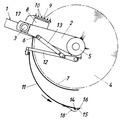
- In der Zeichnung ist als Ausführungsbeispiel das bürstenseitige Ende eines erfindungsgemäßen Bürstenauslegers im Teilschema veranschaulicht.
- Ein Bürstenausleger 1 ist an einem Tunnelwaschfahrzeug kardanisch um eine Hoch- und Querachse schwenkbar und in jede Schwenkstellung einstellbar abgestützt. Am Ende des Auslegers 1 sitzt ein Bürstenträger 2, der um seine Längsachse gegenüber dem Ausleger gedreht werden kann, wobei vorzugsweise eine Querachse 3 des Bürstenträgers 2 überdies aus ihrer zum Ausleger 1 normalen Lage über Stelltriebe mit ihrer Drehachse gegenüber dem Ausleger geneigt werden.
- Am Bürstenträger ist eine nur in ihren Umrissen dargestellte Walzenbürste 4 mittels eines Ölmotors 5 drehend antreibbar angebracht. In Abwandlung der beschriebenen Konstruktion kann auch die Achse 3 als reine Querachse ausgeführt sein und die Bürste 4 über Stelltriebe mit ihrer Drehachse gegenüber dem Ausleger 1 geneigt werden.
- Am Bürstenträger 2 ist bei 6 eine schürzenartige Teilabdeckung 7 angebracht. Die bisher beschriebene Konstruktion ist Stand der Technik.
- Am Bürstenträger ist eine Halterung 8 für einen Düsenbalken 9 angebracht, über dessen Einzeldüsen 10 eine Waschflüssigkeit auf die Bürste bzw. unmittelbar auf die Tunnelwand aufgespritzt werden kann. Beim Ausführungsbeispiel wird angenommen, daß das Tunnelwaschfahrzeug nach links fährt und die Bürste 4 vorzugsweise in einer dem Uhrzeigersinn entgegengesetzten Drehrichtung mit variabler Geschwindigkeit antreibbar ist.
- Zusätzlich zu der Teilabdeckung 7 ist ein zweiter Schürzenteil 11 vorhanden, der an außerhalb der Teilabdeckung 7 angebrachten bzw. durch Schlitze der Abdeckung 7 geführten Schwenkarmen 12 gehalten ist und über an den Armen 12 angreifende, hydraulische Zylinder-Kolbeneinheiten 13 aus der dargestellten die Teilabdeckung 7 überlappenden Ruhestellung unter Verringerung der Überlappung ausstellbar ist, bis er in der Endlage gemeinsam mit der Abdekkung 7 die Bürste 4 um wenigstens 170 bzw. 180° umschließt. Am Vorderrand 14 des Schürzenteiles 11 ist ein Düsenbalken 15 mit Spritzdüsen 16 angebracht, über die eine Spülflüssigkeit ausgesprüht wird. Durch Verstellung des Schürzenteiles 11 können der Abstand der Düsen 16 von der Tunnelwand und auch der Anstellwinkel, unter dem die Spritzstrahlen auf die Tunnelwand auftreffen, zusätzlich eingestellt werden. Versorgungsleitungen 17, 18 für die Düsen 10, 16 wurden strichpunktiert angedeutet.
- Die Teilabdeckung 7 kann an den Schwenkarmen 12 und die Schürze 7 an ihrer Befestigungsstelle 6 in eine Transportstellung klappbar gelagert werden.
Claims (3)
- Bürstenausleger für Tunnelwaschfahrzeuge, mit dem eine drehend antreibbare Walzenbürste (4) auf ihren jeweiligen Arbeitsbereich einstellbar ist, wobei der Bürste (4) am Ausleger (1) ebenfalls auf den Arbeitsbereich einstellbare Spritz- oder Sprühdüsen (10, 16) für Wasch- und Spülflüssigkeit vor- und nachgeordnet sind und am Ausleger (1) eine die Bürste (4) vom Ausleger (1) bis über ihre Lagerstelle umschließende, schürzenartige, gewölbte Teilabdeckung (7) für die Bürstenrückseite vorgesehen ist, dadurch gekennzeichnet, daß ein zweiter Schürzenteil (11) vorgesehen ist, der über eine Antriebseinrichtung (13) aus einer die Teilabdeckung (7) überlappenden Ruhestellung über wählbare Zwischenlagen bis zu einer die Bürste (4) gemeinsam mit der Teilabdeckung um wenigstens 170° umschließenden Endstellung ausfahrbar ist, wobei vorzugsweise Spritz- oder Sprühdüsen (16) für die Spülflüssigkeit zur Erzielung eines optimalen Reinigungseffektes an diesem zweiten Schürzenteil (11) angebracht sind.
- Bürstenausleger nach Anspruch 1, dadurch gekennzeichnet, daß die Spritz- oder Sprühdüsen (16) in Form eines Düsenbalkens (15) am Vorderrand (14) des zweiten Schürzenteiles (11) angebracht sind.
- Bürstenausleger nach Anspruch 1 oder 2, dadurch gekennzeichnet, daß die Teilabdeckung (7) und der zweite Schürzenteil (11) an ihren Halterungen (6, 12) in eine Transportstellung anklappbar angebracht sind.
Applications Claiming Priority (2)
| Application Number | Priority Date | Filing Date | Title |
|---|---|---|---|
| AT911/93 | 1993-05-10 | ||
| AT91193A AT398442B (de) | 1993-05-10 | 1993-05-10 | Bürstenausleger für tunnelwaschfahrzeuge |
Publications (3)
| Publication Number | Publication Date |
|---|---|
| EP0624691A2 true EP0624691A2 (de) | 1994-11-17 |
| EP0624691A3 EP0624691A3 (de) | 1995-03-08 |
| EP0624691B1 EP0624691B1 (de) | 1996-11-27 |
Family
ID=3502679
Family Applications (1)
| Application Number | Title | Priority Date | Filing Date |
|---|---|---|---|
| EP19940890083 Expired - Lifetime EP0624691B1 (de) | 1993-05-10 | 1994-05-10 | Bürstenausleger für Tunnelwaschfahrzeuge |
Country Status (3)
| Country | Link |
|---|---|
| EP (1) | EP0624691B1 (de) |
| AT (1) | AT398442B (de) |
| DE (1) | DE59401113D1 (de) |
Cited By (1)
| Publication number | Priority date | Publication date | Assignee | Title |
|---|---|---|---|---|
| CN113802499A (zh) * | 2021-08-23 | 2021-12-17 | 武汉轻工大学 | 一种栏杆清扫装置 |
Families Citing this family (1)
| Publication number | Priority date | Publication date | Assignee | Title |
|---|---|---|---|---|
| CN109024396B (zh) * | 2018-07-28 | 2020-11-27 | 安徽南博机器人有限公司 | 一种喷嘴升降装置 |
Family Cites Families (6)
| Publication number | Priority date | Publication date | Assignee | Title |
|---|---|---|---|---|
| GB1352066A (en) * | 1971-01-25 | 1974-05-15 | British Municipal Corp Of Birm | Mobile cleansing machine |
| AT344232B (de) * | 1976-01-14 | 1978-07-10 | Zellinger Gmbh | Tunnelwaschfahrzeug |
| DE2737418A1 (de) * | 1977-08-19 | 1979-03-01 | Messerschmitt Boelkow Blohm | Ortsunabhaengige flugzeugwaschmaschine |
| AT380711B (de) * | 1984-12-04 | 1986-06-25 | Zellinger Gmbh | Buerstenausleger fuer ein tunnelwaschfahrzeug |
| GB8502714D0 (en) * | 1985-02-02 | 1985-03-06 | Craig J | Road sweeper assembly |
| FR2635024B1 (fr) * | 1988-08-02 | 1990-11-09 | Protee Gie | Outil de nettoyage de surfaces surplombantes telles que plafonds et voutes |
-
1993
- 1993-05-10 AT AT91193A patent/AT398442B/de not_active IP Right Cessation
-
1994
- 1994-05-10 EP EP19940890083 patent/EP0624691B1/de not_active Expired - Lifetime
- 1994-05-10 DE DE59401113T patent/DE59401113D1/de not_active Expired - Fee Related
Cited By (2)
| Publication number | Priority date | Publication date | Assignee | Title |
|---|---|---|---|---|
| CN113802499A (zh) * | 2021-08-23 | 2021-12-17 | 武汉轻工大学 | 一种栏杆清扫装置 |
| CN113802499B (zh) * | 2021-08-23 | 2023-08-25 | 武汉轻工大学 | 一种栏杆清扫装置 |
Also Published As
| Publication number | Publication date |
|---|---|
| ATA91193A (de) | 1994-04-15 |
| EP0624691A3 (de) | 1995-03-08 |
| AT398442B (de) | 1994-12-27 |
| DE59401113D1 (de) | 1997-01-09 |
| EP0624691B1 (de) | 1996-11-27 |
Similar Documents
| Publication | Publication Date | Title |
|---|---|---|
| DE1430617C3 (de) | Vorrichtung zum Reinigen von Fahrzeugen | |
| EP1034994A2 (de) | Fahrzeugwaschanlage | |
| WO2010105760A1 (de) | Kehrgerät für eine oberfläche | |
| CH598422A5 (en) | Mobile tunnel cleaning and spraying machine | |
| EP0624691B1 (de) | Bürstenausleger für Tunnelwaschfahrzeuge | |
| DE3503049A1 (de) | Fassadenreinigungsvorrichtung | |
| EP1044859A2 (de) | Trocknungsvorrichtung zum Trocknen von Fahrzeugen in Fahrzeugwaschanlagen | |
| EP1663746B1 (de) | Düsenanordnung für eine fahrzeugwaschanlage und verfahren zur reinigung eines fahrzeugs | |
| DE2145715A1 (de) | Kehrmaschine mit rotierenden Drehbürsten | |
| DE19955424C2 (de) | Einrichtung und Verfahren zur Reinigung eines der Aufnahme von verunreinigtem Wasser dienenden Behälters | |
| EP0391010A1 (de) | Kehrmaschine | |
| AT361533B (de) | Strassenreinigungsgeraet | |
| EP3835684A1 (de) | Selbstfahrendes reinigungsgerät zum befahren und reinigen von solar-modulen | |
| DE29506844U1 (de) | Hydraulischer Gieß- und Reinigungsarm für mobile Einrichtungen | |
| DE4027613A1 (de) | Verfahren zum buerstenlosen reinigen von fahrzeugen und portalwaschanlage | |
| DE102008042119B4 (de) | Portalwaschanlage für Kraftfahrzeuge | |
| WO1993010911A1 (de) | Vorrichtung zur aussenkonservierung von kraftfahrzeugen | |
| DE10221353B4 (de) | Bodenreinigungsmaschine | |
| EP0989819B1 (de) | Einrichtung zum waschen von vorhängen aller art | |
| DE2410925A1 (de) | Tunnelwandwascheinrichtung und verfahren zum einsatz derselben | |
| DE3444710C2 (de) | ||
| EP1176072A2 (de) | Behandlungsanlage für Fahrzeuge, insbesondere Wasch- oder Polieranlage | |
| DE8701171U1 (de) | Frontanbaugerät für ein Straßenreinigungskraftfahrzeug o.dgl. | |
| DE8118653U1 (de) | Flaechenreinigungsgeraet | |
| CH692155A5 (de) | Strassenreinigungsmaschine. |
Legal Events
| Date | Code | Title | Description |
|---|---|---|---|
| PUAI | Public reference made under article 153(3) epc to a published international application that has entered the european phase |
Free format text: ORIGINAL CODE: 0009012 |
|
| AK | Designated contracting states |
Kind code of ref document: A2 Designated state(s): CH DE FR IT LI |
|
| PUAL | Search report despatched |
Free format text: ORIGINAL CODE: 0009013 |
|
| AK | Designated contracting states |
Kind code of ref document: A3 Designated state(s): CH DE FR IT LI |
|
| 17P | Request for examination filed |
Effective date: 19950821 |
|
| GRAG | Despatch of communication of intention to grant |
Free format text: ORIGINAL CODE: EPIDOS AGRA |
|
| GRAH | Despatch of communication of intention to grant a patent |
Free format text: ORIGINAL CODE: EPIDOS IGRA |
|
| 17Q | First examination report despatched |
Effective date: 19960506 |
|
| GRAH | Despatch of communication of intention to grant a patent |
Free format text: ORIGINAL CODE: EPIDOS IGRA |
|
| GRAA | (expected) grant |
Free format text: ORIGINAL CODE: 0009210 |
|
| AK | Designated contracting states |
Kind code of ref document: B1 Designated state(s): CH DE FR IT LI |
|
| PG25 | Lapsed in a contracting state [announced via postgrant information from national office to epo] |
Ref country code: IT Free format text: LAPSE BECAUSE OF FAILURE TO SUBMIT A TRANSLATION OF THE DESCRIPTION OR TO PAY THE FEE WITHIN THE PRESCRIBED TIME-LIMIT;WARNING: LAPSES OF ITALIAN PATENTS WITH EFFECTIVE DATE BEFORE 2007 MAY HAVE OCCURRED AT ANY TIME BEFORE 2007. THE CORRECT EFFECTIVE DATE MAY BE DIFFERENT FROM THE ONE RECORDED. Effective date: 19961127 Ref country code: FR Effective date: 19961127 |
|
| REG | Reference to a national code |
Ref country code: CH Ref legal event code: NV Representative=s name: DIPL.-ING. W. STEUDTNER |
|
| REF | Corresponds to: |
Ref document number: 59401113 Country of ref document: DE Date of ref document: 19970109 |
|
| EN | Fr: translation not filed | ||
| PLBE | No opposition filed within time limit |
Free format text: ORIGINAL CODE: 0009261 |
|
| STAA | Information on the status of an ep patent application or granted ep patent |
Free format text: STATUS: NO OPPOSITION FILED WITHIN TIME LIMIT |
|
| 26N | No opposition filed | ||
| PGFP | Annual fee paid to national office [announced via postgrant information from national office to epo] |
Ref country code: CH Payment date: 19990531 Year of fee payment: 6 |
|
| PG25 | Lapsed in a contracting state [announced via postgrant information from national office to epo] |
Ref country code: LI Free format text: LAPSE BECAUSE OF NON-PAYMENT OF DUE FEES Effective date: 20000531 Ref country code: CH Free format text: LAPSE BECAUSE OF NON-PAYMENT OF DUE FEES Effective date: 20000531 |
|
| REG | Reference to a national code |
Ref country code: CH Ref legal event code: PL |
|
| PGFP | Annual fee paid to national office [announced via postgrant information from national office to epo] |
Ref country code: DE Payment date: 20090514 Year of fee payment: 16 |
|
| PG25 | Lapsed in a contracting state [announced via postgrant information from national office to epo] |
Ref country code: DE Free format text: LAPSE BECAUSE OF NON-PAYMENT OF DUE FEES Effective date: 20101201 |