EP0624692A2 - Machine de travail pour enlever des traçes d'huile ou de matière grasse des surfaces de routes - Google Patents
Machine de travail pour enlever des traçes d'huile ou de matière grasse des surfaces de routes Download PDFInfo
- Publication number
- EP0624692A2 EP0624692A2 EP94107270A EP94107270A EP0624692A2 EP 0624692 A2 EP0624692 A2 EP 0624692A2 EP 94107270 A EP94107270 A EP 94107270A EP 94107270 A EP94107270 A EP 94107270A EP 0624692 A2 EP0624692 A2 EP 0624692A2
- Authority
- EP
- European Patent Office
- Prior art keywords
- water
- working machine
- chassis
- machine according
- sprayed
- Prior art date
- Legal status (The legal status is an assumption and is not a legal conclusion. Google has not performed a legal analysis and makes no representation as to the accuracy of the status listed.)
- Withdrawn
Links
Images


Classifications
-
- E—FIXED CONSTRUCTIONS
- E01—CONSTRUCTION OF ROADS, RAILWAYS, OR BRIDGES
- E01H—STREET CLEANING; CLEANING OF PERMANENT WAYS; CLEANING BEACHES; DISPERSING OR PREVENTING FOG IN GENERAL CLEANING STREET OR RAILWAY FURNITURE OR TUNNEL WALLS
- E01H1/00—Removing undesirable matter from roads or like surfaces, with or without moistening of the surface
- E01H1/001—Treatment of dispersed oil or similar pollution on roads, for instance devices for applying treating agents
-
- E—FIXED CONSTRUCTIONS
- E01—CONSTRUCTION OF ROADS, RAILWAYS, OR BRIDGES
- E01H—STREET CLEANING; CLEANING OF PERMANENT WAYS; CLEANING BEACHES; DISPERSING OR PREVENTING FOG IN GENERAL CLEANING STREET OR RAILWAY FURNITURE OR TUNNEL WALLS
- E01H1/00—Removing undesirable matter from roads or like surfaces, with or without moistening of the surface
- E01H1/02—Brushing apparatus, e.g. with auxiliary instruments for mechanically loosening dirt
- E01H1/05—Brushing apparatus, e.g. with auxiliary instruments for mechanically loosening dirt with driven brushes
- E01H1/053—Brushing apparatus, e.g. with auxiliary instruments for mechanically loosening dirt with driven brushes having vertical axes
-
- E—FIXED CONSTRUCTIONS
- E01—CONSTRUCTION OF ROADS, RAILWAYS, OR BRIDGES
- E01H—STREET CLEANING; CLEANING OF PERMANENT WAYS; CLEANING BEACHES; DISPERSING OR PREVENTING FOG IN GENERAL CLEANING STREET OR RAILWAY FURNITURE OR TUNNEL WALLS
- E01H1/00—Removing undesirable matter from roads or like surfaces, with or without moistening of the surface
- E01H1/10—Hydraulically loosening or dislodging undesirable matter; Raking or scraping apparatus ; Removing liquids or semi-liquids e.g., absorbing water, sliding-off mud
- E01H1/101—Hydraulic loosening or dislodging, combined or not with mechanical loosening or dislodging, e.g. road washing machines with brushes or wipers
- E01H1/103—Hydraulic loosening or dislodging, combined or not with mechanical loosening or dislodging, e.g. road washing machines with brushes or wipers in which the soiled loosening or washing liquid is removed, e.g. by suction
Definitions
- the invention relates to a working machine for removing mineral oils and greases on traffic route surfaces, in particular provided with ecological surface coverings, provided on a self-propelled chassis.
- the removal of these traces of oil is per se the responsibility of the causer, who in many cases, however, can no longer be determined and therefore cannot be claimed.
- Fire brigade used that sprinkles the contaminated area with a suction granulate, which will be swept up again after a while, assuming that the suction granulate has absorbed the oil or fat that forms the trace, so that the danger is eliminated.
- At least one storage container each for the water to be sprayed on and for sucked-back oil or grease-laden water are arranged on the chassis, of which at least the latter is designed as a pressure / vacuum container that one to the Storage tank connected pressure pump for the water to be sprayed on and a connection line to spray nozzles in a brush head on the front of the chassis, a brush head is provided, which is provided with two counter-rotating cup brushes, the spray nozzles for the water to be sprayed on in the area of the cup brushes, preferably by their axes guided, arranged, and that the back of the chassis has a suction bar for receiving the sprayed, now oil or fat-containing liquid, the absorption taking place under the action of a vacuum drawn in the reservoir for the back-sucked water.
- high-pressure spray nozzles can also be provided, which are preferably combined in a spray bar.
- hard surfaces - such as runway concrete - can also be removed, so that these surfaces can also be renovated.
- the vehicle is then provided with a high pressure pump generating the injection pressure; it goes without saying that, in order to reduce the weight, the pressure pump and high-pressure pump can be exchanged depending on the intended application.
- the squeegee is provided with a rubber cover at the front in the direction of travel and with a rubber lip in the direction of travel at the rear; While the leading rubber cover keeps away unnecessary false air, the rear rubber lip wipes off the sprayed-on liquid, thus improving the cleaning effect and preventing substantial water residues on the surface of the traffic route.
- both are arranged on the chassis so as to be height-adjustable.
- a parallel linkage ensures that the height is shifted in parallel.
- the brush head and suction bar can be pivoted about a horizontal axis, the necessary here Swiveling to a (relatively) small swivel angle in the range of up to about 15 ° is sufficient to compensate for different road inclinations.
- the brush head and the suction beam are advantageously arranged on the chassis in such a way that horizontal displacements can be carried out.
- a water heater is provided in the water supply, upstream or downstream of the high-pressure pump, which is preferably operable with the fuel of the motor driving the machine. With this heating of the water to be sprayed on, a special cleaning effect is achieved when highly viscous masses have to be removed. It is also advantageous if a metering device is provided in order to be able to add detergents, surfactants and / or enzymes to the water to be sprayed on. With these agents, which can be adapted to the present application, the dissolving of the oils or fats is facilitated, these generally being emulsified in the sprayed water. Storage containers are advantageously provided on the chassis for these additives.
- a water jet pump-like device is advantageously used as the metering device, in which the water to be sprayed is passed through a venturi nozzle at high speed, the dynamic pressure of the water being increased and the static pressure being reduced at a given total pressure, the design being such that that this reduction in static pressure is sufficient to suck in the additives.
- the inflow cross section is narrowed, a needle which can be screwed into the suction opening of the metering device and which can be used to adjust the suction cross section, is advantageously used.
- a cyclone separator is switched on in the connection line from the suction / pressure vessel of the receptacle for the liquid that is sucked back to the vacuum unit.
- the separation effect prevents damage to the vacuum unit.
- a blow-out bar is provided in addition to the chassis and is supplied with air by the vacuum pump, possibly via an additional air valve.
- This blow-out bar which advantageously contains a linear air outlet, shielding with a flat air jet is achieved, the blown-out air being at the same time propellant air to be able to drive back the sprayed-on liquid, which could run off to the side, for example due to an inclined or curved surface.
- the blow-out bar on its side facing the assigned chassis side of the chassis with an apron made of an essentially air-impermeable material, a plastic film or the like is advantageous. Mistake.
- the brush head is preceded by a granule spreader which is connected to a granulate storage container via a conveying device.
- a granulate feed in the direction of travel is possible in front of the disc brushes, the granulate improving the cleaning effect through mechanical abrasion.
- the granulate is conveyed pneumatically to the task, for example.
- This granule spreader is also advantageous for winter use, as it prevents the self-propelled working machine from slipping on snow or ice.
- the sprayed water is frost-proof, for example due to added glycol, and does not form an ice track on the traffic route.
- a liquid de-icing spray bar is attached to the rear of the vehicle in order to protect road users from ice icy if there is water residue.
- a water high-pressure pump with a controllable pressure part absorbs the amount of water pre-programmed for the cleaning process.
- an emulsifier is supplied via a metering pump. Both media are brought to temperature and fed to the continuously remote-controlled rotating nozzles via flexible lines. The speed of rotation of the rotating nozzles can be changed continuously and is pressed onto the surface to be cleaned via a fine control valve. It is also possible to move the entire nozzle unit to the side by about half the chassis width in order to optimally massage the emulsion into inaccessible curbs and surfaces.
- a hot steam system operated with diesel fuel is installed, which can be regulated continuously up to 150 ° C.
- a suction bar with suction injection nozzles is arranged in the rear area of the vehicle, which guides the oil-water emulsion into the suction / pressure container via flexible lines.
- This suction bar with the nozzles themselves can be laterally displaced in the same way as the brush head, in order to ensure that liquids are also absorbed without residue when the edge zones are inadequate.
- a side channel pump with a silencer is arranged on the side of the vehicle in order to remain below the noise level critical for the environment at maximum performance; Pipes that lead to two side cyclone separators with an integrated double ball shut-off valve unit in the upper area of the suction / pressure vessel via two suction dome ball valves, the air is routed via a common line to the 4-way valve and the side channel blower. The exhaust air from the side channel blower is routed to the 4-way valve via the exhaust silencer and introduced into the air distribution system. This air pipe distribution system is used to inevitably direct the water-oil emulsions to the suction nozzles when the road is steep.
- connection point for a manual mechanical cleaning device is installed in order to be able to carry out the surface cleaning wherever mechanical cleaning is not possible.
- the two cyclone separators with a double ball valve are provided for safety reasons to prevent the oil-water emulsion (and thus also solid impurities) from being carried away on rough roads and incorrect driving style.
- the mobile work machine primarily removes traces of oil or grease on traffic routes that are hazardous to traffic, whereby the environment and sewage system are not burdened with the oil residues that are still present, which is still the case today when sprinkled with oil-binding agents. The frequency of accidents is also reduced because the application of granular oil binders leads to an increased risk of slipping. Cleaning with the proposed work machine avoids these disadvantages.
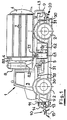
- FIGS. 1 and 2 show the work machine 1 for removing oil or grease traces on traffic routes with a wheel 2 Chassis with the longitudinal members 9, on which the driver's cab 3 and clean water tank 7 are arranged on both sides of the receptacle 4 designed as a suction / pressure vessel.
- a connecting line 7.1 connects the fresh water storage container 7 to the high-pressure pump 6.1 provided on the chassis, the drive of which is carried out via a separate, for example a hydraulic motor, or is removed from the engine of the vehicle analogously to the drive of the vacuum unit 5 also provided on the chassis.
- the pressurized water is conducted to the brush head 10 via lines (not shown in more detail) and is sprayed there in the area of the pot brushes 1, preferably by the waves carrying the pot brushes 15 onto the surface of the area of the traffic route to be cleaned.
- a storage container (not shown in more detail), or also several substances for additives, such as detergents, enzymes or other substances adapted to the application, is provided in the vehicle body and connected to the fresh water supply line 7.1 by an intake line, these lines being in the area of a metering device 29 ( Fig. 8) are merged.
- the metering device (not shown in more detail) advantageously consists of a device similar to a water jet pump, the suction connection of which is connected to the additive line 29.1 (FIG.
- a heating device 6.2 which is also provided on the chassis, allows the fresh water to be heated up to a temperature range (limited by pressure), which generally extends up to 150 ° C.
- the suction bar 20 is provided, with which the liquid sprayed onto the surface to be cleaned is sucked up again.
- air is blown onto this surface in such a way that liquid which runs off is pushed back.
- this blowing air is blown out via the blowing bars 30, which run under the vehicle within its wheelbase and which open approximately V-shaped towards the front of the vehicle, whereby Lateral aprons 31 reaching approximately to the surface prevent this blown-out air from flowing away.
- the brush head 10 is shown, which is attached to the chassis of the working machine 1 with a brush head carrier 11 so that the brush head 10 can be moved sideways, and shifted from the (shown) central position to one of the side positions can be, it goes without saying that a two-sided displacement is also possible.
- a support plate 12 is provided with a parallel guide 13 and a vertical cylinder 14, the oppositely driven cup brushes 15 being arranged at the free end of the parallel guides 12.
- the parallel guides 12 ensure that the cup brushes 15 always have the appropriate position relative to the surface of the traffic route.
- the support plate 12 When the surface is inclined transversely to the course of the traffic route, the support plate 12 is designed such that it can be pivoted about a horizontal axis lying parallel to the direction of travel, in order to compensate for the inclination of the roadway, this pivotability also being advantageous on curved surfaces.
- the drives of the pot brushes 15 are advantageously in the area of the brush holders of the parallel guides 12 and are designed as hydraulic motors 16 which can be driven by the vehicle hydraulics; a belt drive 17 is provided for the power transmission. It goes without saying that a drive with the pressurized water, which is supplied to the spray nozzles in the area of the pot brushes 15, is also possible.
- the suction bar 20 Arranged at the rear of the vehicle is the suction bar 20 shown in more detail in FIGS. 5 and 6, which absorbs the liquid sprayed on in the front area again after a certain exposure time. Since such vehicles move very slowly and there is an entire length of vehicle between the brush head and the squeegee, the times between spraying and massaging and resuming are in the range of 101 seconds.
- the squeegee is attached to the chassis by a squeegee support 21 which can be moved sideways, for which a horizontal cylinder 22.1 is provided.
- a squeegee holder 22 takes over the fixed end of the parallel guides 23, with the aid of which the squeegee 25 can be adjusted in height relative to the surface of the traffic route, a vertical cylinder 24, one end 24.1 of which is supported on the frame, providing the drive.
- the side of the suction slot 25.2 leading in the direction of travel is provided with an apron 26 which extends to near the surface of the traffic route and which is sufficiently flexible to be able to rest thereon.
- the trailing side of the suction slot 25.2 is provided with a stable rubber lip 27, which rests on the surface of the traffic route and pushes together any liquid residues to be taken up by the suction nozzle 25.2.
- the sucked-up liquid is fed together with the detected air through line 4.3 to the receptacle 4, solely under the effect of the vacuum drawn in the receptacle 4; The separation of air and liquid then takes place in the receptacle 4.
- FIGS. 7 and 8 show the process diagrams “vacuum” and water “, from which the interaction of the individual components can be seen: the liquid present on the surface of the traffic route to be cleaned is sucked up by the suction bar 20 and fed to the receptacle 4 via the connecting line 4.3, in which a separation of air and liquid takes place The sucked-in air is fed via the lines 8.1 connected to the suction domes 4.1 provided with shut-off valves to the cyclones 8, in which residual droplets and other particles are separated out, the cleaned air leaving the cyclones the lines 8.3, which are combined to a four-way valve 8.4.
- the suction line 8.3 is connected to the suction port 5.2 of the vacuum unit 5, the outlet 5.3 of which is in turn led to the four-way valve 8.4, and from its outlet to the blow bar 30.
- the four-way valve allowed switching, so that the container 4, for example for emptying, can be pressurized.
- the connecting line 4.3 of the receptacle 4 is connected to the suction bar 20, and sucks in the air there together with the absorbed liquid, which is blown out again via the blowing bar 30.
- the suction bar 30 is used as an air inlet.
- the supply water is fed from the storage containers 7 to a pressure pump 6.1, which is followed by a water heater 6.2.
- the pressurized water is sucked out of the pockets 7, which are connected to one another and to the filler necks 7.2 via compensation lines 7.1, according to the “water” process diagram of FIG. 8, pressurized in a pressure pump 6.1 and, if necessary, in the downstream heating device heated up; to the water pretreated in this way, the additives coming from a storage container 29.2 via line 29.1 are added in a metering device 29.
- This water is then fed via line 6.3 to the brush head 10 in order to be sprayed onto the surface to be cleaned.
- a cut-off tap 6.4 to which a hose reel 6.6 with a hose 6.5 can be connected in order to be able to connect a hand cleaning gun 6.7 for any necessary reworking.
Landscapes
- Engineering & Computer Science (AREA)
- Architecture (AREA)
- Civil Engineering (AREA)
- Structural Engineering (AREA)
- Environmental & Geological Engineering (AREA)
- Cleaning In General (AREA)
- Cleaning By Liquid Or Steam (AREA)
- Lubricants (AREA)
Applications Claiming Priority (2)
| Application Number | Priority Date | Filing Date | Title |
|---|---|---|---|
| DE9307097U | 1993-05-10 | ||
| DE9307097U DE9307097U1 (de) | 1993-05-10 | 1993-05-10 | Arbeitsmaschine zum Beseitigen von Öl- oder Fettspuren auf Verkehrsweg-Oberflächen u.dgl. |
Publications (2)
| Publication Number | Publication Date |
|---|---|
| EP0624692A2 true EP0624692A2 (fr) | 1994-11-17 |
| EP0624692A3 EP0624692A3 (fr) | 1995-03-08 |
Family
ID=6893105
Family Applications (1)
| Application Number | Title | Priority Date | Filing Date |
|---|---|---|---|
| EP94107270A Withdrawn EP0624692A3 (fr) | 1993-05-10 | 1994-05-10 | Machine de travail pour enlever des traçes d'huile ou de matière grasse des surfaces de routes. |
Country Status (2)
| Country | Link |
|---|---|
| EP (1) | EP0624692A3 (fr) |
| DE (1) | DE9307097U1 (fr) |
Cited By (15)
| Publication number | Priority date | Publication date | Assignee | Title |
|---|---|---|---|---|
| EP0773327A1 (fr) * | 1995-11-10 | 1997-05-14 | Rainer Scholz | Procédé et dispositif pour nettoyer des routes et autre surfaces de circulation contaminées des matériaux écologiquement dangereux et/ou avec rugosité réduite |
| GB2352166A (en) * | 1999-07-21 | 2001-01-24 | Hydro Dynamix Ltd | Wet cleaning apparatus and method, in particular for road and like surfaces, using rinsing and suction |
| EP1020565A3 (fr) * | 1999-01-12 | 2001-12-05 | Lehner Agrar GmbH | Agencement d'épandage d'un liant et dispositif de nettoyage comportant un tel agencement |
| EP1160381A3 (fr) * | 2000-05-31 | 2003-08-06 | M-U-T Maschinen-Umwelttechnik- Transportanlagen Gesellschaft M.B.H. | Dispositif d'élimination de traces de freinage ou d'abrasion de pneux en élastomère d'une chaussée |
| DE10221353A1 (de) * | 2002-05-10 | 2003-11-20 | Hako Gmbh | Bodenreinigungsmaschine |
| EP1298253A3 (fr) * | 2001-09-27 | 2004-01-14 | Walter &Co. GmbH | Dispositif de nettoyage du sol à l'aide d'un fluide |
| EP1852471A1 (fr) * | 2006-05-05 | 2007-11-07 | Juchem-Asphaltmischwerk-St. Wendel GmbH & Co. | Procédé d' élimination sélective de composés aromatiques et/ou composés phénoliques a partir d'un matériau de construction contenant du brai de houille et une fondation de construction routière contaminée |
| CN104762903A (zh) * | 2015-04-09 | 2015-07-08 | 山东交通学院 | 一种路面油液清洁专用装置 |
| CN106638399A (zh) * | 2017-02-17 | 2017-05-10 | 河北工业大学 | 一种陆地油品回收装置及收集方法 |
| CN106884400A (zh) * | 2017-04-17 | 2017-06-23 | 无锡市金沙田科技有限公司 | 多功能电动道路清扫车 |
| CN108755541A (zh) * | 2018-06-01 | 2018-11-06 | 永春县义翔技术咨询有限公司 | 一种环卫洗路车及其清洗方法 |
| CN111945646A (zh) * | 2020-08-14 | 2020-11-17 | 河海大学 | 一种隧道路面油污清洗与收集一体装置 |
| CN113481908A (zh) * | 2021-06-23 | 2021-10-08 | 郑州铁路职业技术学院 | 一种土木工程作业除尘装置 |
| CN114045774A (zh) * | 2021-11-25 | 2022-02-15 | 张先平 | 一种房屋建筑施工除积水装置 |
| CN116474992A (zh) * | 2023-04-28 | 2023-07-25 | 广东图特精密五金科技股份有限公司 | 一种滑轮配件的加工装置 |
Families Citing this family (9)
| Publication number | Priority date | Publication date | Assignee | Title |
|---|---|---|---|---|
| DE29514554U1 (de) * | 1995-09-01 | 1995-11-16 | Hako-Werke Gmbh & Co, 23843 Bad Oldesloe | Fahrbare Naßreinigungsmaschine |
| RU2272861C1 (ru) * | 2004-11-01 | 2006-03-27 | Открытое акционерное общество специального машиностроения и металлургии "Мотовилихинские заводы" | Поливочно-моечное оборудование |
| DE102007004933B4 (de) | 2007-01-26 | 2009-10-15 | Wehner Metallbau Gmbh & Co. Kg | Reinigungsfahrzeug |
| DE102008029648A1 (de) | 2008-06-24 | 2009-12-31 | Wehner Metallbau Gmbh & Co. Kg | Vorrichtung zur manuellen Reinigung von Straßen und dergleichen |
| DE102008029647A1 (de) | 2008-06-24 | 2009-12-31 | Wehner Metallbau Gmbh & Co. Kg | Reinigungsfahrzeug |
| FR2960127B1 (fr) * | 2010-05-19 | 2012-07-06 | Chesneau Environnement | Ensemble mobile de desherbage et/ou de nettoyage par la vapeur, comprenant deux cloches de diffusion de vapeur |
| DE102010024500A1 (de) * | 2010-06-10 | 2011-12-15 | Norbert Fischer | Vorrichtung und Verfahren zum Beseitigen von Schmutz |
| ITRM20120478A1 (it) * | 2012-10-09 | 2014-04-10 | Sicurezza E Ambiente S P A | Autocarro polifunzionale perfezionato atto alla pulizia di aree interessate da incidenti stradali per il rapido ripristino della viabilita' e della sicurezza stradale |
| CN115156135A (zh) * | 2022-06-15 | 2022-10-11 | 中国电建集团华东勘测设计研究院有限公司 | 一种用于供水隧洞的移动式清基装置及快速清基方法 |
Family Cites Families (7)
| Publication number | Priority date | Publication date | Assignee | Title |
|---|---|---|---|---|
| DE2323588B2 (de) * | 1973-05-10 | 1978-11-09 | Woma Apparatebau Wolfgang Maasberg & Co Gmbh, 4100 Duisburg | Als Fahrzeug ausgebildeter Waschsauger zum Reinigen von Straßen u.a. Flächen |
| US4580312A (en) * | 1984-02-10 | 1986-04-08 | Raaij Karel W M Van | Broom and suction assembly for a street sweeper |
| CH678342A5 (en) * | 1984-06-06 | 1991-08-30 | Peter Ag Konrad | Dust wetting road sweeping machine |
| DE3538539A1 (de) * | 1985-10-30 | 1987-05-07 | Joachim Dipl Ing Meier | Fahrbare vorrichtung zur reinigung insbesondere von fahrbahnen |
| FR2610651A1 (fr) * | 1987-02-05 | 1988-08-12 | Commissariat Energie Atomique | Vehicule de nettoiement par projection et aspiration de liquide |
| US5005253A (en) * | 1989-10-12 | 1991-04-09 | Noelle John A | Surface cleaning apparatus |
| DE9106129U1 (de) * | 1991-05-17 | 1992-09-24 | Ing. Alfred Schmidt Gmbh, 7822 St Blasien | Kraftfahrzeug mit einer Vorrichtung zum Ausbringen von Auftaumittel auf Verkehrsflächen |
-
1993
- 1993-05-10 DE DE9307097U patent/DE9307097U1/de not_active Expired - Lifetime
-
1994
- 1994-05-10 EP EP94107270A patent/EP0624692A3/fr not_active Withdrawn
Cited By (18)
| Publication number | Priority date | Publication date | Assignee | Title |
|---|---|---|---|---|
| DE19541887A1 (de) * | 1995-11-10 | 1997-05-15 | Rainer Scholz | Verfahren und Vorrichtung zur Abreinigung einer durch umweltschädliche Medien kontaminierten und/oder in ihrer Griffigkeit beeinträchtigten Fahrbahn oder sonstigen Verkehrsfläche |
| EP0773327A1 (fr) * | 1995-11-10 | 1997-05-14 | Rainer Scholz | Procédé et dispositif pour nettoyer des routes et autre surfaces de circulation contaminées des matériaux écologiquement dangereux et/ou avec rugosité réduite |
| EP1020565A3 (fr) * | 1999-01-12 | 2001-12-05 | Lehner Agrar GmbH | Agencement d'épandage d'un liant et dispositif de nettoyage comportant un tel agencement |
| GB2352166A (en) * | 1999-07-21 | 2001-01-24 | Hydro Dynamix Ltd | Wet cleaning apparatus and method, in particular for road and like surfaces, using rinsing and suction |
| EP1160381A3 (fr) * | 2000-05-31 | 2003-08-06 | M-U-T Maschinen-Umwelttechnik- Transportanlagen Gesellschaft M.B.H. | Dispositif d'élimination de traces de freinage ou d'abrasion de pneux en élastomère d'une chaussée |
| EP1298253A3 (fr) * | 2001-09-27 | 2004-01-14 | Walter &Co. GmbH | Dispositif de nettoyage du sol à l'aide d'un fluide |
| DE10221353B4 (de) * | 2002-05-10 | 2014-12-24 | Hako-Werke Gmbh | Bodenreinigungsmaschine |
| DE10221353A1 (de) * | 2002-05-10 | 2003-11-20 | Hako Gmbh | Bodenreinigungsmaschine |
| EP1852471A1 (fr) * | 2006-05-05 | 2007-11-07 | Juchem-Asphaltmischwerk-St. Wendel GmbH & Co. | Procédé d' élimination sélective de composés aromatiques et/ou composés phénoliques a partir d'un matériau de construction contenant du brai de houille et une fondation de construction routière contaminée |
| CN104762903A (zh) * | 2015-04-09 | 2015-07-08 | 山东交通学院 | 一种路面油液清洁专用装置 |
| CN106638399A (zh) * | 2017-02-17 | 2017-05-10 | 河北工业大学 | 一种陆地油品回收装置及收集方法 |
| CN106638399B (zh) * | 2017-02-17 | 2018-04-06 | 河北工业大学 | 一种陆地油品回收装置及收集方法 |
| CN106884400A (zh) * | 2017-04-17 | 2017-06-23 | 无锡市金沙田科技有限公司 | 多功能电动道路清扫车 |
| CN108755541A (zh) * | 2018-06-01 | 2018-11-06 | 永春县义翔技术咨询有限公司 | 一种环卫洗路车及其清洗方法 |
| CN111945646A (zh) * | 2020-08-14 | 2020-11-17 | 河海大学 | 一种隧道路面油污清洗与收集一体装置 |
| CN113481908A (zh) * | 2021-06-23 | 2021-10-08 | 郑州铁路职业技术学院 | 一种土木工程作业除尘装置 |
| CN114045774A (zh) * | 2021-11-25 | 2022-02-15 | 张先平 | 一种房屋建筑施工除积水装置 |
| CN116474992A (zh) * | 2023-04-28 | 2023-07-25 | 广东图特精密五金科技股份有限公司 | 一种滑轮配件的加工装置 |
Also Published As
| Publication number | Publication date |
|---|---|
| DE9307097U1 (de) | 1994-09-22 |
| EP0624692A3 (fr) | 1995-03-08 |
Similar Documents
| Publication | Publication Date | Title |
|---|---|---|
| EP0624692A2 (fr) | Machine de travail pour enlever des traçes d'huile ou de matière grasse des surfaces de routes | |
| EP0773327B1 (fr) | Procédé et dispositif pour nettoyer des routes et autre surfaces de circulation contaminées des matériaux écologiquement dangereux et/ou avec rugosité réduite | |
| EP2210982B1 (fr) | Machine de nettoyage mobile haute pression pour sols en plastique extérieurs et son utilisation | |
| DE68907234T2 (de) | Verfahren zum Trennen von asbestenthaltendem Material und Verhindern von schwebendem Staub. | |
| DE19853190A1 (de) | Rotationswäscher mit schrägstehendem Demister | |
| DE2019646A1 (de) | Transportable Vorrichtung zur Reinigung und teilweise Trocknung von Teppichen und Teppichbelaegen | |
| EP1160381A2 (fr) | Dispositif d'élimination de traces de freinage ou d'abrasion de pneux en élastomère d'une chaussée | |
| WO1999020843A1 (fr) | Procede et dispositif pour le nettoyage de gorges de rails | |
| DE102010011418B4 (de) | Vorrichtung, System und Verfahren zum Nassreinigen von Kunstrasen | |
| DE102016002922A1 (de) | Neue Reinigungsvorrichtung und Verfahren zur Reinigung | |
| DE4101417A1 (de) | Selbstfahrender deckenfertiger | |
| DE202016001593U1 (de) | Neue Reinigungsvorrichtung | |
| DE2145715A1 (de) | Kehrmaschine mit rotierenden Drehbürsten | |
| EP1312419B1 (fr) | Dispositif et procédé de nettoyage des caillebotis dans les cabines de peinture | |
| EP0447601A1 (fr) | Dispositif de nettoyage de marquages routiers | |
| DE69733576T2 (de) | Einrichtung zum reinigen von oberflächen mit sprüzerstäuber und wiederverwendungseinheit | |
| EP1185739B1 (fr) | Dispositif mobile pour le nettoyage de gorges de rails avec un liquide | |
| DE20020793U1 (de) | Vorrichtung zum Reinigen von Behältern, insbesondere zur Innenreinigung von Mülltonnen | |
| AT2321U1 (de) | Strassenreinigungsmaschine | |
| DE1546073A1 (de) | Verfahren und Vorrichtung zum Waschen und Entfetten von Gegenstaenden | |
| DE8914626U1 (de) | Wiederaufbereitungsgerät für Festkörperstrahlmittel | |
| DE4340528C2 (de) | Vorrichtung zur Innenreinigung von Tanks | |
| DE102010044185A1 (de) | Pflasterfugenreiniger | |
| DE2432971A1 (de) | Verfahren zur dammbindung beim reinigen von strassen u. dgl. mit hilfe eines kehrgeraets | |
| DE1144310B (de) | Verfahren zur Reinigung des Unterbaus von Strassen oder aehnlichen Flaechen mittels eines Hochdruckwasserstrahles und Vorrichtung zur Durchfuehrung des Verfahrens |
Legal Events
| Date | Code | Title | Description |
|---|---|---|---|
| PUAI | Public reference made under article 153(3) epc to a published international application that has entered the european phase |
Free format text: ORIGINAL CODE: 0009012 |
|
| AK | Designated contracting states |
Kind code of ref document: A2 Designated state(s): AT BE CH DE FR GB IT LI NL |
|
| PUAL | Search report despatched |
Free format text: ORIGINAL CODE: 0009013 |
|
| AK | Designated contracting states |
Kind code of ref document: A3 Designated state(s): AT BE CH DE FR GB IT LI NL |
|
| 18D | Application deemed to be withdrawn |
Effective date: 19950909 |
|
| STAA | Information on the status of an ep patent application or granted ep patent |
Free format text: STATUS: THE APPLICATION IS DEEMED TO BE WITHDRAWN |