EP0624746B1 - Soupape d'arrêt - Google Patents
Soupape d'arrêt Download PDFInfo
- Publication number
- EP0624746B1 EP0624746B1 EP94107132A EP94107132A EP0624746B1 EP 0624746 B1 EP0624746 B1 EP 0624746B1 EP 94107132 A EP94107132 A EP 94107132A EP 94107132 A EP94107132 A EP 94107132A EP 0624746 B1 EP0624746 B1 EP 0624746B1
- Authority
- EP
- European Patent Office
- Prior art keywords
- chamber
- sub
- piston
- valve
- shut
- Prior art date
- Legal status (The legal status is an assumption and is not a legal conclusion. Google has not performed a legal analysis and makes no representation as to the accuracy of the status listed.)
- Expired - Lifetime
Links
Images

Classifications
-
- F—MECHANICAL ENGINEERING; LIGHTING; HEATING; WEAPONS; BLASTING
- F16—ENGINEERING ELEMENTS AND UNITS; GENERAL MEASURES FOR PRODUCING AND MAINTAINING EFFECTIVE FUNCTIONING OF MACHINES OR INSTALLATIONS; THERMAL INSULATION IN GENERAL
- F16K—VALVES; TAPS; COCKS; ACTUATING-FLOATS; DEVICES FOR VENTING OR AERATING
- F16K31/00—Actuating devices; Operating means; Releasing devices
- F16K31/12—Actuating devices; Operating means; Releasing devices actuated by fluid
- F16K31/122—Actuating devices; Operating means; Releasing devices actuated by fluid the fluid acting on a piston
-
- F—MECHANICAL ENGINEERING; LIGHTING; HEATING; WEAPONS; BLASTING
- F16—ENGINEERING ELEMENTS AND UNITS; GENERAL MEASURES FOR PRODUCING AND MAINTAINING EFFECTIVE FUNCTIONING OF MACHINES OR INSTALLATIONS; THERMAL INSULATION IN GENERAL
- F16K—VALVES; TAPS; COCKS; ACTUATING-FLOATS; DEVICES FOR VENTING OR AERATING
- F16K47/00—Means in valves for absorbing fluid energy
Definitions
- the invention relates to a check valve which can be actuated pneumatically by a piston / cylinder arrangement.
- a pneumatically actuated passage valve with an inlet and outlet for a medium-containing valve housing is known, the passage of which is blocked or opened by a closure element at the valve seat.
- the closure element is actuated by a piston rod, which is displaceably guided in the cylinder and divides the cylinder into a first and a second partial chamber.
- the piston itself has a cavity that is open to the first partial chamber and into which a cylindrical projection projects, which receives a seal and at the same time reduces the dead volume of the first chamber.
- the invention has for its object to form a check valve of the type mentioned so that on the one hand a quick switching of the check valve is possible, but on the other hand excessive control forces on the piston in the opening direction of the valve are avoided when controlling high pressures.
- the volume displacement element considerably reduces the dead volume in the first chamber when the shut-off valve is closed. Since the closure element of the valve according to the invention is loaded in its closed position by the medium against the valve seat, a force acts on the piston in the direction of the valve seat via the piston rod. To open the valve, the entire force acting on the piston must be compensated for by building up a control pressure in the first chamber. After the closure element has been lifted off the sealing seat, an excess force arises on the piston, since the opposite force component generated by the pressure of the medium is eliminated. This usually leads to a strong acceleration of the piston at very high pressure of the medium.
- the flow conditions in the first partial chamber are favorably influenced by radially extending ribs provided on the displacement element. However, so that the ribs do not increase the dead volume in the first chamber, the contour of each rib essentially corresponds to the contour of the adjacent wall area of the cavity.
- those areas of the volume displacement element which are on the side facing away from the piston are correspondingly, i.e. complementary to the wall of the first sub-chamber.
- An additional amplification of the effect according to the invention achieve by a throttle element which is arranged between the first sub-chamber and an inlet on the cylinder and is provided for the introduction of a control medium into the first sub-chamber. This prevents the rapid pressure reduction in the first sub-chamber from being compensated for by an uncontrolled control medium after the initial phase of a switching process.
- a check valve 10 designed according to the invention is shown in cross section in the closed state.
- the check valve 10 consists essentially of a cylinder 12, a piston 14, a piston rod 16, a closure element 18 and a valve seat 20.
- the closure element 18 blocks a medium in the direction of flow S, which passes through an inlet channel 22 into the check valve 10 and when open Check valve 10 flows out again via an outlet channel 24.
- the input channel 22 and the output channel 24 are delimited by a valve housing 25 which is connected to the cylinder 12.
- the closure element 18 rests on the valve seat 20 and closes a passage 26 which is surrounded by the valve seat 20.
- the closure element 18 is fixedly connected to the piston 14 via the piston rod 16.
- Prestressed springs 28 and 30 press on the piston 14 in the direction of the closed position of the closure element 18.
- the closure element 18 is in the closed position of the closure element 18 via the piston 14 and the piston rod 16 by the springs 28 and 30 and by the pressure of the medium charged.
- the cylinder 12, the piston 14, the piston rod 16, the closure element 18 and the springs 28 and 30 are arranged coaxially.
- the piston 14 is bell-shaped, so that there is a cavity 32 within the piston 14.
- the piston 14 divides the cylinder 12 into a first partial chamber 34 and a second partial chamber 36.
- the cavity 32 is open in the direction of the first partial chamber 34.
- the first sub-chamber 34 has a small dead volume when the shut-off valve 10 is closed, while the second sub-chamber 36 has an increased volume.
- a first connection circuit 38 is provided for the first subchamber 34 and a second 40 for the second subchamber 36.
- the piston 14 is moved to open or close the check valve 10 by appropriately setting a gas pressure in the first sub-chamber 34 or the second sub-chamber 36.
- the gas is moved into and out of the first and second subchambers 34, 36 by known devices for controlling the piston 14. A detailed description of these known devices is not necessary.
- a throttle 39, 41 is provided in the manner of a thin bore, which flows into the subchamber 34, 36 too quickly or flows too quickly out of the subchamber 34, 36 prevented.
- the throttle 39, 41 is matched to the volume reduction effect according to the invention in the first sub-chamber 34 when the check valve 10 is opened.
- a closure cap 42 is screwed onto the cylinder 12 and has an annular extension which extends in the direction of the piston 14 and serves as a stop 44 for the piston 14. Furthermore, the closure cap 42 has grooves 421, 422 into which the springs 28 and 30, which load the piston 14 in the closed position of the closure element 18, engage. As a result, the springs 28, 30 in the piston 14 are secured against radial movement relative to the closure cap 42.
- a seal 46 is provided in an annular groove 142 open radially outward in the piston 14.
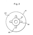
- a volume displacement element 48 is introduced into the first partial chamber 34.
- the volume displacement element 48 is mounted coaxially to the piston rod 16, the piston rod 16 being axially displaceable relative to the volume displacement element 48.
- the volume displacement element 48 has a sleeve-shaped part 481 and a disk-shaped part 482.
- the sleeve-shaped part 481 protrudes into the cavity 32 of the piston 14.
- the disk-shaped part 482 adjoins the sleeve-shaped part 481 and extends to the wall of the cylinder 12, which radially delimits the first partial chamber 34.
- the disk-shaped part 482 is designed to match the contour of the cylinder wall and the surface contour of the inner end face of the first partial chamber 34.
- ribs 483 which are offset by 90 ° protrude from the sleeve-shaped part 481 of the volume displacement element 48.
- the shape of these ribs 483 is adapted to the adjacent areas of the cavity 32 of the piston 14.
- the dead volume that is to say the volume available for the control pressure when the shut-off valve 10 is closed in the first partial chamber 34, is greatly reduced by the volume displacement element 48.
- a control pressure is built up in the first subchamber 34, that is to say in the dead volume, by supplying compressed air to the first subchamber 34 through the connection 38, for example.
- the piston 14 and thus the piston rod 16 moves with the closure element 18 upwards .
- the volume in the first sub-chamber 34 increases greatly in relation to the initial volume, so that the control pressure which was necessary for the initial movement of the piston 14 is reduced correspondingly quickly. Since the actuating force in the opening direction is now greatly reduced, an excessive, sudden acceleration of the piston 14 is avoided.
Landscapes
- Engineering & Computer Science (AREA)
- General Engineering & Computer Science (AREA)
- Mechanical Engineering (AREA)
- Lift Valve (AREA)
- Fluid-Damping Devices (AREA)
- Check Valves (AREA)
Claims (5)
- Soupape d'arrêt (10) qui peut être actionnée pneumatiquement par un groupement piston/ cylindre (12, 14), comportant une cage de soupape (25) comprenant un canal d'arrivée et un canal de sortie (22, 24) pour un fluide et dont le passage (26) près du siège de soupape (20) est fermé ou ouvert par un élément de fermeture (18) qui est actionné par l'intermédiaire d'une tige de piston (16) par le piston (14) mobile dans le cylindre (12) et divisant le cylindre (12) en une première chambre partielle (34) et en une seconde chambre partielle (36), et qui dans sa position fermée, est sollicité par le fluide contre le siège de soupape (20), le piston (14) présentant un creux (32) ouvert vers la première chambre partielle (34) et dans lequel un élément de déplacement du volume (48) dépasse à l'intérieur de la première chambre partielle (34) qui pour l'ouverture de l'élément de fermeture (18), présente une pression supérieure à celle de la seconde chambre partielle (36) et en cas de soupape d'arrêt (10) fermée, réduit au moins considérablement le volume mort de la première chambre partielle (34), l'élément de déplacement du volume (48) présentant des nervures (483) radiales dont le contour correspond sensiblement au contour de la zone adjacente de la paroi du creux (32) et l'élément de fermeture (18) étant déplacé par la commande de la pression au moins dans la première chambre partielle (34).
- Soupape d'arrêt selon la revendication 1 dans laquelle l'élément de déplacement du volume (48) est disposé coaxialement par rapport à la tige de piston (16).
- Soupape d'arrêt selon l'une quelconque des revendications précédentes, dans laquelle les zones de l'élément de déplacement du volume (48) qui sont adjacentes à la paroi délimitant la première chambre partielle (34), ont sur leur côté opposé au piston (14), un contour qui est conçu comme étant complémentaire au contour de cette paroi.
- Soupape d'arrêt selon l'une quelconque des revendications précédentes, dans laquelle l'élément de déplacement du volume (48) est fixé dans la première chambre partielle (34) selon un mouvement allant dans un sens opposé par rapport au cylindre (12).
- Soupape d'arrêt comportant un raccord (38, 40) pour un fluide à commande pneumatique pour la première et/ou la seconde chambre partielle (34, 36), selon l'une quelconque des revendications précédentes, dans laquelle il est prévu un papillon (39) entre la première chambre partielle (34) et le raccord (38) et/ou un papillon (41) entre la seconde chambre partielle (36) et le raccord (40).
Applications Claiming Priority (2)
| Application Number | Priority Date | Filing Date | Title |
|---|---|---|---|
| DE9307166U | 1993-05-11 | ||
| DE9307166U DE9307166U1 (de) | 1993-05-11 | 1993-05-11 | Sperrventil |
Publications (3)
| Publication Number | Publication Date |
|---|---|
| EP0624746A2 EP0624746A2 (fr) | 1994-11-17 |
| EP0624746A3 EP0624746A3 (fr) | 1995-02-22 |
| EP0624746B1 true EP0624746B1 (fr) | 1997-07-16 |
Family
ID=6893158
Family Applications (1)
| Application Number | Title | Priority Date | Filing Date |
|---|---|---|---|
| EP94107132A Expired - Lifetime EP0624746B1 (fr) | 1993-05-11 | 1994-05-06 | Soupape d'arrêt |
Country Status (2)
| Country | Link |
|---|---|
| EP (1) | EP0624746B1 (fr) |
| DE (2) | DE9307166U1 (fr) |
Families Citing this family (5)
| Publication number | Priority date | Publication date | Assignee | Title |
|---|---|---|---|---|
| DE19641073C2 (de) * | 1996-10-04 | 2000-07-13 | Adolf Harald Sonnleitner | Druckmittelbetätigbares Ventil |
| DE19932743C2 (de) * | 1999-07-14 | 2003-10-09 | Thomas Scholzen | Regelventilanlage mit pneumatischem Stellantrieb |
| DE10336065A1 (de) * | 2003-08-06 | 2005-03-03 | Bürkert Werke GmbH & Co. KG | Pneumatischer Ventilantrieb |
| DE202006007591U1 (de) * | 2006-05-12 | 2007-06-21 | Bopp & Reuther Messtechnik Gmbh | Ventilvorrichtung zum Druckausgleich |
| CN113202967B (zh) * | 2021-04-30 | 2022-10-04 | 中国空气动力研究与发展中心设备设计与测试技术研究所 | 一种用于低温风洞的超低温开关阀 |
Family Cites Families (3)
| Publication number | Priority date | Publication date | Assignee | Title |
|---|---|---|---|---|
| DE1074940B (de) * | 1960-02-04 | LICENTIA Patent-Verwaltungs-G.m.b.H., Frankfurt/M | Hydraulischer Antrieb für Schncllschlußventile | |
| US3029061A (en) * | 1959-07-16 | 1962-04-10 | Don R Hoxworth | Air-hydraulic control unit |
| DE1809448A1 (de) * | 1968-11-18 | 1970-06-11 | Edmund Pietrowski | Pneumatisch betaetigtes Durchgangsventil |
-
1993
- 1993-05-11 DE DE9307166U patent/DE9307166U1/de not_active Expired - Lifetime
-
1994
- 1994-05-06 DE DE59403357T patent/DE59403357D1/de not_active Expired - Lifetime
- 1994-05-06 EP EP94107132A patent/EP0624746B1/fr not_active Expired - Lifetime
Also Published As
| Publication number | Publication date |
|---|---|
| EP0624746A2 (fr) | 1994-11-17 |
| DE59403357D1 (de) | 1997-08-21 |
| DE9307166U1 (de) | 1993-07-15 |
| EP0624746A3 (fr) | 1995-02-22 |
Similar Documents
| Publication | Publication Date | Title |
|---|---|---|
| DE3523917A1 (de) | Von einem steuerorgan betaetigtes steuerungsventil | |
| EP1435028B1 (fr) | Soupape de regulation de pression, en particulier soupape de regulation de pression a action proportionnelle | |
| DE3305092C2 (fr) | ||
| EP1525144B1 (fr) | Valve de regulation de pression | |
| DE3329790A1 (de) | Ventiltraeger fuer kolbenverdichter | |
| EP0223935B1 (fr) | Valve de commande de pression de freinage commandés par deux circuits | |
| DE3322912A1 (de) | Mehrwege-sitzventil | |
| EP0624746B1 (fr) | Soupape d'arrêt | |
| DE69100337T2 (de) | Antriebsvorrichtung durch Flüssigkeitsdruck für einen Kolben. | |
| DE3343172A1 (de) | Steuerventil | |
| LU84377A1 (de) | Einstellbares drosselventil | |
| DE4201442A1 (de) | Elektronisch geregeltes direkt betätigtes 3-Wege-Druckregelventil für gasförmige und flüssige Medien | |
| DE69804426T2 (de) | Dreiwege-Druckregelventil | |
| EP1440225A2 (fr) | Actionneur hydraulique pour soupape a deux voies a gaz | |
| DE3311816C1 (de) | Druckbegrenzungsventil fuer Druckluftbremsanlagen von Kraftfahrzeugen | |
| EP0123866B1 (fr) | Cylindre à air comprimé, en particulier cylindre de frein à air comprimé | |
| EP0483585B1 (fr) | Valve d'étranglement proportionelle réglable à contre-réaction | |
| EP0147589A2 (fr) | Régulateur de pression commandé par force | |
| EP1629208A1 (fr) | Soupape de regulation de pression proportionnelle | |
| EP0289712A2 (fr) | Régulateur de pression | |
| DE4129774A1 (de) | Druckausgeglichenes schaltventil | |
| EP0132695A2 (fr) | Valve de commande pour freins à air comprimé de véhicules sur rails | |
| DE19626323B4 (de) | Sicherheitsventileinrichtung | |
| DE3639149C2 (de) | Lastabhängig steuerbare Bremskraftregeleinrichtung | |
| EP0312718B1 (fr) | Valve de commande de pression de freinage commandée par deux circuits |
Legal Events
| Date | Code | Title | Description |
|---|---|---|---|
| PUAI | Public reference made under article 153(3) epc to a published international application that has entered the european phase |
Free format text: ORIGINAL CODE: 0009012 |
|
| AK | Designated contracting states |
Kind code of ref document: A2 Designated state(s): DE FR GB SE |
|
| PUAL | Search report despatched |
Free format text: ORIGINAL CODE: 0009013 |
|
| AK | Designated contracting states |
Kind code of ref document: A3 Designated state(s): DE FR GB SE |
|
| 17P | Request for examination filed |
Effective date: 19950512 |
|
| 17Q | First examination report despatched |
Effective date: 19951227 |
|
| GRAG | Despatch of communication of intention to grant |
Free format text: ORIGINAL CODE: EPIDOS AGRA |
|
| GRAH | Despatch of communication of intention to grant a patent |
Free format text: ORIGINAL CODE: EPIDOS IGRA |
|
| GRAH | Despatch of communication of intention to grant a patent |
Free format text: ORIGINAL CODE: EPIDOS IGRA |
|
| GRAA | (expected) grant |
Free format text: ORIGINAL CODE: 0009210 |
|
| AK | Designated contracting states |
Kind code of ref document: B1 Designated state(s): DE FR GB SE |
|
| GBT | Gb: translation of ep patent filed (gb section 77(6)(a)/1977) |
Effective date: 19970725 |
|
| REF | Corresponds to: |
Ref document number: 59403357 Country of ref document: DE Date of ref document: 19970821 |
|
| ET | Fr: translation filed | ||
| PLBE | No opposition filed within time limit |
Free format text: ORIGINAL CODE: 0009261 |
|
| STAA | Information on the status of an ep patent application or granted ep patent |
Free format text: STATUS: NO OPPOSITION FILED WITHIN TIME LIMIT |
|
| 26N | No opposition filed | ||
| REG | Reference to a national code |
Ref country code: GB Ref legal event code: IF02 |
|
| REG | Reference to a national code |
Ref country code: FR Ref legal event code: TP |
|
| PGFP | Annual fee paid to national office [announced via postgrant information from national office to epo] |
Ref country code: SE Payment date: 20100517 Year of fee payment: 17 |
|
| REG | Reference to a national code |
Ref country code: SE Ref legal event code: EUG |
|
| PG25 | Lapsed in a contracting state [announced via postgrant information from national office to epo] |
Ref country code: SE Free format text: LAPSE BECAUSE OF NON-PAYMENT OF DUE FEES Effective date: 20110507 |
|
| PGFP | Annual fee paid to national office [announced via postgrant information from national office to epo] |
Ref country code: DE Payment date: 20130529 Year of fee payment: 20 Ref country code: GB Payment date: 20130521 Year of fee payment: 20 |
|
| PGFP | Annual fee paid to national office [announced via postgrant information from national office to epo] |
Ref country code: FR Payment date: 20130603 Year of fee payment: 20 |
|
| REG | Reference to a national code |
Ref country code: DE Ref legal event code: R071 Ref document number: 59403357 Country of ref document: DE |
|
| REG | Reference to a national code |
Ref country code: GB Ref legal event code: PE20 Expiry date: 20140505 |
|
| PG25 | Lapsed in a contracting state [announced via postgrant information from national office to epo] |
Ref country code: GB Free format text: LAPSE BECAUSE OF EXPIRATION OF PROTECTION Effective date: 20140505 |
|
| PG25 | Lapsed in a contracting state [announced via postgrant information from national office to epo] |
Ref country code: DE Free format text: LAPSE BECAUSE OF EXPIRATION OF PROTECTION Effective date: 20140507 |