EP0624768B1 - Einrichtung zum Bewegen, insbesondere Mischen und/oder Trocknen eines Gutes - Google Patents
Einrichtung zum Bewegen, insbesondere Mischen und/oder Trocknen eines Gutes Download PDFInfo
- Publication number
- EP0624768B1 EP0624768B1 EP94810284A EP94810284A EP0624768B1 EP 0624768 B1 EP0624768 B1 EP 0624768B1 EP 94810284 A EP94810284 A EP 94810284A EP 94810284 A EP94810284 A EP 94810284A EP 0624768 B1 EP0624768 B1 EP 0624768B1
- Authority
- EP
- European Patent Office
- Prior art keywords
- container
- shaft
- wall section
- wall
- funnel
- Prior art date
- Legal status (The legal status is an assumption and is not a legal conclusion. Google has not performed a legal analysis and makes no representation as to the accuracy of the status listed.)
- Expired - Lifetime
Links
Images

Classifications
-
- F—MECHANICAL ENGINEERING; LIGHTING; HEATING; WEAPONS; BLASTING
- F26—DRYING
- F26B—DRYING SOLID MATERIALS OR OBJECTS BY REMOVING LIQUID THEREFROM
- F26B9/00—Machines or apparatus for drying solid materials or objects at rest or with only local agitation; Domestic airing cupboards
- F26B9/06—Machines or apparatus for drying solid materials or objects at rest or with only local agitation; Domestic airing cupboards in stationary drums or chambers
- F26B9/08—Machines or apparatus for drying solid materials or objects at rest or with only local agitation; Domestic airing cupboards in stationary drums or chambers including agitating devices, e.g. pneumatic recirculation arrangements
- F26B9/082—Machines or apparatus for drying solid materials or objects at rest or with only local agitation; Domestic airing cupboards in stationary drums or chambers including agitating devices, e.g. pneumatic recirculation arrangements mechanically agitating or recirculating the material being dried
- F26B9/085—Machines or apparatus for drying solid materials or objects at rest or with only local agitation; Domestic airing cupboards in stationary drums or chambers including agitating devices, e.g. pneumatic recirculation arrangements mechanically agitating or recirculating the material being dried moving the material in a substantially vertical sense using conveyors or agitators, e.g. screws or augers with vertical axis, which are positioned inside the drying enclosure
-
- B—PERFORMING OPERATIONS; TRANSPORTING
- B01—PHYSICAL OR CHEMICAL PROCESSES OR APPARATUS IN GENERAL
- B01F—MIXING, e.g. DISSOLVING, EMULSIFYING OR DISPERSING
- B01F27/00—Mixers with rotary stirring devices in fixed receptacles; Kneaders
- B01F27/05—Stirrers
- B01F27/09—Stirrers characterised by the mounting of the stirrers with respect to the receptacle
- B01F27/091—Stirrers characterised by the mounting of the stirrers with respect to the receptacle with elements co-operating with receptacle wall or bottom, e.g. for scraping the receptacle wall
-
- B—PERFORMING OPERATIONS; TRANSPORTING
- B01—PHYSICAL OR CHEMICAL PROCESSES OR APPARATUS IN GENERAL
- B01F—MIXING, e.g. DISSOLVING, EMULSIFYING OR DISPERSING
- B01F27/00—Mixers with rotary stirring devices in fixed receptacles; Kneaders
- B01F27/80—Mixers with rotary stirring devices in fixed receptacles; Kneaders with stirrers rotating about a substantially vertical axis
- B01F27/92—Mixers with rotary stirring devices in fixed receptacles; Kneaders with stirrers rotating about a substantially vertical axis with helices or screws
- B01F27/921—Mixers with rotary stirring devices in fixed receptacles; Kneaders with stirrers rotating about a substantially vertical axis with helices or screws with helices centrally mounted in the receptacle
- B01F27/9211—Mixers with rotary stirring devices in fixed receptacles; Kneaders with stirrers rotating about a substantially vertical axis with helices or screws with helices centrally mounted in the receptacle the helices being surrounded by a guiding tube
-
- B—PERFORMING OPERATIONS; TRANSPORTING
- B01—PHYSICAL OR CHEMICAL PROCESSES OR APPARATUS IN GENERAL
- B01F—MIXING, e.g. DISSOLVING, EMULSIFYING OR DISPERSING
- B01F27/00—Mixers with rotary stirring devices in fixed receptacles; Kneaders
- B01F27/80—Mixers with rotary stirring devices in fixed receptacles; Kneaders with stirrers rotating about a substantially vertical axis
- B01F27/92—Mixers with rotary stirring devices in fixed receptacles; Kneaders with stirrers rotating about a substantially vertical axis with helices or screws
- B01F27/921—Mixers with rotary stirring devices in fixed receptacles; Kneaders with stirrers rotating about a substantially vertical axis with helices or screws with helices centrally mounted in the receptacle
- B01F27/9214—Mixers with rotary stirring devices in fixed receptacles; Kneaders with stirrers rotating about a substantially vertical axis with helices or screws with helices centrally mounted in the receptacle with additional mixing elements other than helices; having inner and outer helices; with helices surrounding a guiding tube
Definitions
- the present invention relates to a facility according to the preamble of claim 1.
- the facility serves in particular to this, powder mixtures, granules and the like, for example To produce food and powdered pharmaceuticals.
- Means for mixing one for example Particulate components of existing goods have one vertical or horizontal axis container, in the interior at least one, several rotatable about the axis of the container Mixer having agitator is stored.
- the good components to be mixed with one another in an Lid of the container existing opening in the interior of the Introduced container. Then the material is stirred using the agitator moved and mixed, with other components and additives, such as liquids, dyes and the like, still added to the good during the mixing process can be.
- a device for drying a good is from the DE-B-1'063'529 known.
- This publication which constitutes the closest prior art, discloses a device with a rotationally symmetrical container for batch drying of cereals and the like.
- a funnel coaxial to the container axis and a screw conveyor passed through the hopper arranged.
- the latter serves to continually one Part of the goods to be dried from the lower part of the container pull off and up through the funnel promote. From there it reaches the top of the funnel as well as between two sieve-like wall sections of Funnel and container down.
- a drying agent for example hot air, into the container and through the sieve-like wall section the container out of this again. Doing so between the two wall sections from top to bottom The desiccant flows through the goods moving below and dries.
- the device known from DE-B-1'063'529 enables optimal drying of grain and the like,
- it has the disadvantage that the entire batch of the goods placed in the container the snail moves more or less evenly, but only is mixed poorly. So if you have different ones, for example components to be mixed together in succession the container, it can take a relatively long time until they are mixed to some extent homogeneously. This is particularly effective when adding small amounts of a substance very disadvantageous because the attached Amount of substance only very slowly in the presented product is distributed.
- US-A-3,797,702 Another device for mixing at least two Components is known from US-A-3,797,702.
- This pre-release discloses a continuously operating facility for adding recycled material to a plastic matrix.
- the facility essentially has one cylindrical container with a vertical axis and a conical bottom that tapers downwards.
- In the container is also a funnel with a conical wall section and a funnel neck arranged.
- Leading through this funnel a shaft rotatably mounted on the lid of the container. This has at its upper section one to the inner wall of the conical Matching wall section and is in your section within the funnel neck as a screw conveyor educated.
- the funnel neck finally ends in an outlet arranged on the cone-shaped base, which via a line is connected to the inlet of an extruder.
- the recycling material through the funnel and the base mass through the the funnel surrounding sub-space is directed from top to bottom to the outlet, with a constant promotion of the recycling material through the agitator and screw conveyor is forced.
- the outlet is then continuously recycled with the same presented basic mass mixed and then by conveyed the outlet into the extruder.
- a mixture of the In this case, the components placed in the container can only be found in the Outlet area instead, but not in the conical part of the im Container arranged funnel. This therefore only serves the recycling material coaxial to the container axis of to convey up to the outlet.
- the invention is now based on DE-B-1'063'529 the task of establishing a facility create the aforementioned disadvantages of the known devices does not have. In particular, this should make it possible become the components of a good relatively quickly and mix gently with each other so that the formed Accordingly, product regardless of the size of the container and regardless of the type of goods, a homogeneous composition as well as the product quality to be achieved.
- FIG. 1 and designated 1 as a whole Facility has a simplified representation Frame 2, which is a relatively large container 3 stationary holds.
- the latter is essentially rotationally symmetrical, So has a vertical axis 4, and has a cylindrical Wall 5, at the lower end of which is a cone-shaped adjoins wall part 6 tapering downwards.
- a lid 7 At its top At the end of the container 3 is also provided with a lid 7, which is detachably attached to the wall 5 and at least one has lockable inlet 8 for filling the goods.
- the conical wall part 6 finally has on its lower End an outlet 9 which is connected to an outlet member 10 is lockable.
- the outlet member 10 is a cone valve trained and has an axially movable, conical Closure element 10a, for example with a manual or pneumatic actuator is adjustable.
- Outlet member 10 also as a slide or ball valve can be trained.
- the interior 11 of the container is defined by an axis 4 coaxial, essentially funnel-shaped wall 12 into a first, inner subspace 11a and a second, outer subspace 11b divided.
- the wall 12 is by holding arms 12a held stationary and has a cone-shaped top open and downwardly tapering wall section 13 which is followed by a cylindrical wall section 14.
- Wave 15 finally leads through the inner part space 11a.
- the lower section 15a of the shaft 15 is with a Conveyor, namely a screw 16 provided through an uninterrupted, helical metallic Band is formed and the material to be mixed is used for this through the cylindrical wall section 14 up into the conical To promote wall section 13.
- the outer diameter the screw helix 16 is dimensioned so that this only through a small space from the inner wall of the Wall section 14 is separated.
- the shaft pierces 15 with its sealed end portion the cover 7 and by a motor, for example a hydraulic motor 18 of the drive device 19 via a transmission at speeds for example 10 to 50 revolutions per minute driven.
- a motor for example a hydraulic motor 18 of the drive device 19 via a transmission at speeds for example 10 to 50 revolutions per minute driven.
- the shaft 15 is not only in the cover 8 but also rotatably mounted on the outlet member 10.
- To it has at its lower end a bore 15c and the closure element 10a of the outlet member 10 on its interior 11 facing surface a suitable in the bore 15c Guide pin 10b so that the shaft 15 on the Closure element 10a plugged on and thereby rotatably mounted can be.
- the guide pin 10b can for example be designed as a needle-bearing guide head.
- the device for example, to form a granular or powdery mix of two or more components outlet 9 is first closed. Then the good components to be mixed together through the opening 8 in the lid 7 into the container 3 are introduced, during which the shaft 15 around the Container axis 4 is rotated so that continuously part of the Good to be mixed from the lower area of the outer part 11b withdrawn and through the cylindrical wall portion 14 conveyed upwards, within the cone-shaped Wall section 13 moved and mixed with the mixing elements 17 and then over the top of the cone-shaped Wall section 13 transported back into the outer part of the room llb becomes. Because the screw spiral 16 to the deepest Can take place of the interior 11, it will the worst mix is caught by the screw and promoted upwards.
- the material is circulated vertically by means of the screw helix 16 and inside the conical wall section 13 gently mixed.
- the conveyance path of the goods is through arrows 21 and 22 indicated.
- Individual components of the Good things as well as additives such as dyes and the like, can also during the rotational movement of the Shaft 15 through the inlet 8 in the cover Container 3 already submitted good part can be added.
- the device according to the invention enables that the substances that have been added after the fact evenly distributed in the good part presented in the container so that the mixing time is significantly reduced.
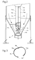
- FIG. 2 Another embodiment of the invention is therefore in the Figure 2 shown.
- the one in this figure as a whole with 101 designated facility is largely similar to that based on The device 1 described 1 formed So like this one from a conical one wall section 113 and a cylindrical wall section 114 formed funnel-shaped wall 112.
- the device 101 has a slightly modified one Conveyor and one formed from two half-shells 114a and 114b cylindrical wall section 114.
- the dimensions of the devices according to the invention can vary widely, with the container usable volume for example in the size of 20 to 200,000 1 can. This allows institutions with a relatively large Usable container volume is also accessible for a service man Hatch so that cleaning, inspection and repair work can be done inside the container, without the lid of the cylindrical wall part of the Container must be separated. Especially for such big ones
- the device shown in FIGS. 2 and 3 is made of the cylindrical half shells 114a and 114b Wall section 114 useful.
- first half shell 114a firmly connected to the conical wall section 113, while the second half-shell 114b by means of it and rotating and locking means arranged on the first half-shell 114a 118 and 119 are pivotally attached in this way is that - as shown in Figure 3 - the interior of the cylindrical wall section and the conveyor element on simple Way for the service man for repair and cleaning purposes can be made accessible.
- the dimensions of the funnel-shaped wall 12 or 112 can be varied.
- the length of the funnel-shaped wall should be dimensioned such that this extends over approximately 3/4 to 2/3 of the height of the interior (11).
- the dimensions and shapes of the mixing tools depending on the material to be mixed and depending on the Vary the size of the container.
- a device according to the invention can be used instead the wing 20 shown in Figure 1 also one of several Segments formed, helical or spiral around the Partition wall 12 arranged flow brake.
- the facilities too may have an electronic control device to the Various control and / or regulation operations for the mixing process perform automatically.
Landscapes
- Chemical & Material Sciences (AREA)
- Chemical Kinetics & Catalysis (AREA)
- Engineering & Computer Science (AREA)
- Mechanical Engineering (AREA)
- General Engineering & Computer Science (AREA)
- Mixers Of The Rotary Stirring Type (AREA)
- Drying Of Solid Materials (AREA)
- Detergent Compositions (AREA)
- Processes Of Treating Macromolecular Substances (AREA)
Description
Claims (8)
- Einrichtung zum chargenweisen Mischen und/oder Trocknen eines Mischgutes mitdadurch gekennzeichnet dass innerhalb des konusförmigen Wandabschnittes (13) mindestens ein drehbares Mischorgan (17) angeordnet ist, dass eine zur Behälterachse (4) koaxiale Welle (15) vorhanden ist, dass an dieser Welle (15) das Förderorgan und das mindestens eine Mischorgan (17) angeordnet sind und dass der am unteren Ende des Behälters (3) angeordnete Auslass (9) ein wahlweise absperrbares Auslass-Organ (10) besitzt, wobei die Welle (15) auch während der Entnahme des Mischgutes um die Behälterachse (4) gedreht werden kann, wobei die Welle (15) dazu am Auslass-Organ (10) gelagert bleibt, so dass das Mischgut gleichmässig und vollständig auslaufen kann.einem vertikalachsigen Behälter (3),einem in den Innenraum des Behälters (3) mündenden oberen Gut-Einlass (8) und einem aus diesem herausführenden unteren Gut-Auslass (9),einer im Innenraum des Behälters (3) zur Behälterachse (4) koaxial angeordneten trichterförmigen Wand (12), die einen sich nach unten konusförmig verjüngenden, oberen Wandabschnitt (13) sowie einen sich an diesen anschliessenden zylindrischen, unteren Wandabschnitt (14) besitzt, undeinem durch den zylindrischen Wandabschnitt (14) hindurchgeführten Förderorgan,
- Einrichtung nach Anspruch 1, dadurch gekennzeichnet, dass die Welle (15) durch die beiden, die trichterförmige Wand (12) bildende Wandabschnitte (13, 14) hindurchgeführt ist.
- Einrichtung nach Anspruch 2, dadurch gekennzeichnet, dass die beiden Enden der durch den inneren Teilraum (lla) hindurchgeführten Welle (15) drehbar gelagert sind.
- Einrichtung nach Anspruch 2 oder 3, dadurch gekennzeichnet, dass das Förderorgan durch eine Schnecken-Wendel (16) gebildet wird.
- Einrichtung nach Anspruch 4, dadurch gekennzeichnet, dass das Förderorgan mindestens an seinem aus dem zylindrischen Wandabschnitt (14,114) herausragenden Endabschnitt eine zur erstgenannten Schnecken-Wendel (16,116) achsensymetrisch angeordnete zweite Schnecken-Wendel (117) besitzt.
- Einrichtung nach einem der Ansprüche 1 bis 5, dadurch gekennzeichnet, dass der Behälter (3) eine zylindrische Wand (5) aufweist, an deren unterem Ende sich ein konusförmiger, sich nach unten verjüngender Wandteil (6) anschliesst.
- Einrichtung nach einem der Ansprüche 1 bis 6, dadurch gekennzeichnet, dass die Länge der im wesentlichen trichterförmigen Wand (12,112) derart bemessen ist, dass sich die trichterförmige Wand (12,112) über ungefähr 3/4 bis 2/3 der Höhe des Innenraumes (11) erstreckt.
- Einrichtung nach einem der Ansprüche 1 bis 7, dadurch gekennzeichnet, dass der zylindrische Wandabschnitt (114) der trichterförmigen Wand (112) aus einer ersten und einer zweiten Halbschale (114a,114b) besteht, wobei die erste Halbschale (114a) mit dem konusförmigen Wandabschnitt (113) fest verbunden und die zweite Halbschale (114b) mittels an ihr und an der ersten Halbschale (114a) angeordneten Dreh- und Verschlusselmitteln (118,119) verschwenkbar an der ersten Halbschale (114a) angeordnet ist.
Applications Claiming Priority (3)
| Application Number | Priority Date | Filing Date | Title |
|---|---|---|---|
| CH1457/93 | 1993-05-13 | ||
| CH145793 | 1993-05-13 | ||
| CH145793 | 1993-05-13 |
Publications (2)
| Publication Number | Publication Date |
|---|---|
| EP0624768A1 EP0624768A1 (de) | 1994-11-17 |
| EP0624768B1 true EP0624768B1 (de) | 1999-12-22 |
Family
ID=4210917
Family Applications (1)
| Application Number | Title | Priority Date | Filing Date |
|---|---|---|---|
| EP94810284A Expired - Lifetime EP0624768B1 (de) | 1993-05-13 | 1994-05-13 | Einrichtung zum Bewegen, insbesondere Mischen und/oder Trocknen eines Gutes |
Country Status (3)
| Country | Link |
|---|---|
| EP (1) | EP0624768B1 (de) |
| AT (1) | ATE188028T1 (de) |
| DE (1) | DE59409018D1 (de) |
Families Citing this family (2)
| Publication number | Priority date | Publication date | Assignee | Title |
|---|---|---|---|---|
| FR3009487B1 (fr) * | 2013-08-09 | 2016-02-26 | Maurice Guillot | Dispositif de sechage de fruits a coque et de graines |
| CN108568919B (zh) * | 2018-04-28 | 2020-02-04 | 重庆瑞霆塑胶有限公司 | 塑胶原料搅拌装置 |
Family Cites Families (5)
| Publication number | Priority date | Publication date | Assignee | Title |
|---|---|---|---|---|
| US2207360A (en) * | 1937-08-20 | 1940-07-09 | Hercules Powder Co Ltd | Drier |
| DE1063529B (de) * | 1958-06-12 | 1959-08-13 | Dr Walther Fischer | Satztrockner fuer Getreide oder aehnliches koerniges Gut |
| US3563399A (en) * | 1967-05-15 | 1971-02-16 | Charles C Shivers | Method for circulating grain stored in a circular bin |
| US3797702A (en) * | 1971-03-29 | 1974-03-19 | J Robertson | Scrap recovery and feed system |
| DE2228429A1 (de) * | 1972-06-10 | 1973-12-20 | Cramer & Soehne Maschf | Mischvorrichtung zum mischen und einfaerben von kunststoffen |
-
1994
- 1994-05-13 DE DE59409018T patent/DE59409018D1/de not_active Expired - Fee Related
- 1994-05-13 AT AT94810284T patent/ATE188028T1/de not_active IP Right Cessation
- 1994-05-13 EP EP94810284A patent/EP0624768B1/de not_active Expired - Lifetime
Also Published As
| Publication number | Publication date |
|---|---|
| DE59409018D1 (de) | 2000-01-27 |
| ATE188028T1 (de) | 2000-01-15 |
| EP0624768A1 (de) | 1994-11-17 |
Similar Documents
| Publication | Publication Date | Title |
|---|---|---|
| EP1118381B1 (de) | Einrichtung zum Behandeln von Stoffen | |
| DE4004005A1 (de) | Einspeisungsvorrichtung fuer teilchenfoermige materialien | |
| DE1531934C3 (de) | Austrag- Misch- und Dosiervorrichtung für schlecht fließende pulverförmige Stoffe | |
| DE2354627A1 (de) | Vorrichtung zum mischen, trennen oder sortieren von trockenen substanzen oder artikeln | |
| EP3219383A1 (de) | Tellercoater zum aufbringen einer oberflächenschicht auf schüttgutartige materialien und mischwerkzeug zur verwendung in einem tellercoater | |
| EP3953029B1 (de) | Verfahren zur entleerung einer vorrichtung zur herstellung von granulaten oder extrudaten | |
| DE2516255C2 (de) | Mischer mit rotierendem mischbehaelter | |
| EP0624768B1 (de) | Einrichtung zum Bewegen, insbesondere Mischen und/oder Trocknen eines Gutes | |
| DE102010060130A1 (de) | Mischvorrichtung und Verfahren zum Mischen eines Schüttgutes oder einer pastösen Masse | |
| DE1118959B (de) | Verfahren und Vorrichtung zur Aufbereitung von Thermoplasten oder Duroplasten | |
| DE1297448B (de) | Vorrichtung zum Mischen von pulverfoermigem bis koernigem Gut | |
| DE2717887A1 (de) | Umwaelzmischer | |
| DE68902294T2 (de) | Vorrichtung zur beschichlung von pulverigen oder koernigen stoffen. | |
| EP3953028B1 (de) | Vorrichtung zur herstellung von granulaten oder extrudaten | |
| WO1986004523A1 (fr) | Tambour d'agglomeration | |
| EP0029072B1 (de) | Mischer zum kontinuierlichen Mischen von Stoffen, insbesondere Kunststoffen | |
| DE20122686U1 (de) | Einrichtung zum Behandeln von Stoffen | |
| DE69624445T2 (de) | Kontinuierlicher Mischer und Verfahren und Vorrichtung zum Beschichten von Materialpartikeln unter Verwendung desselben | |
| DE939617C (de) | Kontinuierlich arbeitende Freifall-Mischmaschine, insbesondere fuer Beton und Moertel | |
| DE102014003760A1 (de) | Vorrichtung und Verfahren zum Beschicken von Schneckenförderem mit rieselfähigem Schüttgut | |
| DE1152597B (de) | Vorrichtung zum Mischen grosser Mengen von Kunststoff-Granulat | |
| DE2409986C2 (de) | Misch- und Beschickungsvorrichtung | |
| DE1850674U (de) | Kesselfoermige vorrichtung zum mischen von kunststoff-granulat. | |
| DE1432026B2 (de) | Kuehlmischer fuer pulverfoermige, koernige oder kleinstueckige kunststoffe | |
| DE19727020A1 (de) | Trommel zum Agglomerieren |
Legal Events
| Date | Code | Title | Description |
|---|---|---|---|
| PUAI | Public reference made under article 153(3) epc to a published international application that has entered the european phase |
Free format text: ORIGINAL CODE: 0009012 |
|
| AK | Designated contracting states |
Kind code of ref document: A1 Designated state(s): AT BE CH DE DK ES FR GB GR IE IT LI LU MC NL PT SE |
|
| 17P | Request for examination filed |
Effective date: 19950304 |
|
| 17Q | First examination report despatched |
Effective date: 19970407 |
|
| GRAG | Despatch of communication of intention to grant |
Free format text: ORIGINAL CODE: EPIDOS AGRA |
|
| GRAG | Despatch of communication of intention to grant |
Free format text: ORIGINAL CODE: EPIDOS AGRA |
|
| GRAH | Despatch of communication of intention to grant a patent |
Free format text: ORIGINAL CODE: EPIDOS IGRA |
|
| GRAH | Despatch of communication of intention to grant a patent |
Free format text: ORIGINAL CODE: EPIDOS IGRA |
|
| GRAA | (expected) grant |
Free format text: ORIGINAL CODE: 0009210 |
|
| AK | Designated contracting states |
Kind code of ref document: B1 Designated state(s): AT BE CH DE DK ES FR GB GR IE IT LI LU MC NL PT SE |
|
| PG25 | Lapsed in a contracting state [announced via postgrant information from national office to epo] |
Ref country code: SE Free format text: THE PATENT HAS BEEN ANNULLED BY A DECISION OF A NATIONAL AUTHORITY Effective date: 19991222 Ref country code: GR Free format text: LAPSE BECAUSE OF NON-PAYMENT OF DUE FEES Effective date: 19991222 Ref country code: ES Free format text: THE PATENT HAS BEEN ANNULLED BY A DECISION OF A NATIONAL AUTHORITY Effective date: 19991222 |
|
| REF | Corresponds to: |
Ref document number: 188028 Country of ref document: AT Date of ref document: 20000115 Kind code of ref document: T |
|
| REG | Reference to a national code |
Ref country code: CH Ref legal event code: EP |
|
| REF | Corresponds to: |
Ref document number: 59409018 Country of ref document: DE Date of ref document: 20000127 |
|
| REG | Reference to a national code |
Ref country code: IE Ref legal event code: FG4D Free format text: GERMAN |
|
| ITF | It: translation for a ep patent filed | ||
| PG25 | Lapsed in a contracting state [announced via postgrant information from national office to epo] |
Ref country code: PT Free format text: LAPSE BECAUSE OF FAILURE TO SUBMIT A TRANSLATION OF THE DESCRIPTION OR TO PAY THE FEE WITHIN THE PRESCRIBED TIME-LIMIT Effective date: 20000322 Ref country code: DK Free format text: LAPSE BECAUSE OF FAILURE TO SUBMIT A TRANSLATION OF THE DESCRIPTION OR TO PAY THE FEE WITHIN THE PRESCRIBED TIME-LIMIT Effective date: 20000322 |
|
| GBT | Gb: translation of ep patent filed (gb section 77(6)(a)/1977) |
Effective date: 20000327 |
|
| ET | Fr: translation filed | ||
| REG | Reference to a national code |
Ref country code: CH Ref legal event code: NV Representative=s name: PATENTANWALTSBUERO EDER AG |
|
| PG25 | Lapsed in a contracting state [announced via postgrant information from national office to epo] |
Ref country code: LU Free format text: LAPSE BECAUSE OF NON-PAYMENT OF DUE FEES Effective date: 20000513 |
|
| PG25 | Lapsed in a contracting state [announced via postgrant information from national office to epo] |
Ref country code: BE Free format text: LAPSE BECAUSE OF NON-PAYMENT OF DUE FEES Effective date: 20000531 |
|
| PLBE | No opposition filed within time limit |
Free format text: ORIGINAL CODE: 0009261 |
|
| STAA | Information on the status of an ep patent application or granted ep patent |
Free format text: STATUS: NO OPPOSITION FILED WITHIN TIME LIMIT |
|
| PG25 | Lapsed in a contracting state [announced via postgrant information from national office to epo] |
Ref country code: IE Free format text: LAPSE BECAUSE OF NON-PAYMENT OF DUE FEES Effective date: 20001116 |
|
| BERE | Be: lapsed |
Owner name: BAUMGARTNER ROLF Effective date: 20000531 |
|
| PG25 | Lapsed in a contracting state [announced via postgrant information from national office to epo] |
Ref country code: MC Free format text: LAPSE BECAUSE OF NON-PAYMENT OF DUE FEES Effective date: 20001130 |
|
| 26N | No opposition filed | ||
| REG | Reference to a national code |
Ref country code: IE Ref legal event code: FD4D |
|
| REG | Reference to a national code |
Ref country code: GB Ref legal event code: IF02 |
|
| PGFP | Annual fee paid to national office [announced via postgrant information from national office to epo] |
Ref country code: NL Payment date: 20020531 Year of fee payment: 9 Ref country code: GB Payment date: 20020531 Year of fee payment: 9 |
|
| PGFP | Annual fee paid to national office [announced via postgrant information from national office to epo] |
Ref country code: CH Payment date: 20020604 Year of fee payment: 9 |
|
| PGFP | Annual fee paid to national office [announced via postgrant information from national office to epo] |
Ref country code: FR Payment date: 20020626 Year of fee payment: 9 |
|
| PGFP | Annual fee paid to national office [announced via postgrant information from national office to epo] |
Ref country code: AT Payment date: 20020705 Year of fee payment: 9 |
|
| PG25 | Lapsed in a contracting state [announced via postgrant information from national office to epo] |
Ref country code: GB Free format text: LAPSE BECAUSE OF NON-PAYMENT OF DUE FEES Effective date: 20030513 Ref country code: AT Free format text: LAPSE BECAUSE OF NON-PAYMENT OF DUE FEES Effective date: 20030513 |
|
| PG25 | Lapsed in a contracting state [announced via postgrant information from national office to epo] |
Ref country code: LI Free format text: LAPSE BECAUSE OF NON-PAYMENT OF DUE FEES Effective date: 20030531 Ref country code: CH Free format text: LAPSE BECAUSE OF NON-PAYMENT OF DUE FEES Effective date: 20030531 |
|
| PGFP | Annual fee paid to national office [announced via postgrant information from national office to epo] |
Ref country code: DE Payment date: 20030616 Year of fee payment: 10 |
|
| PG25 | Lapsed in a contracting state [announced via postgrant information from national office to epo] |
Ref country code: NL Free format text: LAPSE BECAUSE OF NON-PAYMENT OF DUE FEES Effective date: 20031201 |
|
| GBPC | Gb: european patent ceased through non-payment of renewal fee |
Effective date: 20030513 |
|
| REG | Reference to a national code |
Ref country code: CH Ref legal event code: PL |
|
| PG25 | Lapsed in a contracting state [announced via postgrant information from national office to epo] |
Ref country code: FR Free format text: LAPSE BECAUSE OF NON-PAYMENT OF DUE FEES Effective date: 20040130 |
|
| NLV4 | Nl: lapsed or anulled due to non-payment of the annual fee |
Effective date: 20031201 |
|
| REG | Reference to a national code |
Ref country code: FR Ref legal event code: ST |
|
| PG25 | Lapsed in a contracting state [announced via postgrant information from national office to epo] |
Ref country code: DE Free format text: LAPSE BECAUSE OF NON-PAYMENT OF DUE FEES Effective date: 20041201 |
|
| PG25 | Lapsed in a contracting state [announced via postgrant information from national office to epo] |
Ref country code: IT Free format text: LAPSE BECAUSE OF NON-PAYMENT OF DUE FEES Effective date: 20050513 |