EP0624770A2 - Wärmeaustauschvorrichtung - Google Patents
Wärmeaustauschvorrichtung Download PDFInfo
- Publication number
- EP0624770A2 EP0624770A2 EP93310369A EP93310369A EP0624770A2 EP 0624770 A2 EP0624770 A2 EP 0624770A2 EP 93310369 A EP93310369 A EP 93310369A EP 93310369 A EP93310369 A EP 93310369A EP 0624770 A2 EP0624770 A2 EP 0624770A2
- Authority
- EP
- European Patent Office
- Prior art keywords
- heat
- heat exchanging
- unit
- bath fluid
- convecting
- Prior art date
- Legal status (The legal status is an assumption and is not a legal conclusion. Google has not performed a legal analysis and makes no representation as to the accuracy of the status listed.)
- Withdrawn
Links
Images


Classifications
-
- F—MECHANICAL ENGINEERING; LIGHTING; HEATING; WEAPONS; BLASTING
- F28—HEAT EXCHANGE IN GENERAL
- F28D—HEAT-EXCHANGE APPARATUS, NOT PROVIDED FOR IN ANOTHER SUBCLASS, IN WHICH THE HEAT-EXCHANGE MEDIA DO NOT COME INTO DIRECT CONTACT
- F28D1/00—Heat-exchange apparatus having stationary conduit assemblies for one heat-exchange medium only, the media being in contact with different sides of the conduit wall, in which the other heat-exchange medium is a large body of fluid, e.g. domestic or motor car radiators
- F28D1/02—Heat-exchange apparatus having stationary conduit assemblies for one heat-exchange medium only, the media being in contact with different sides of the conduit wall, in which the other heat-exchange medium is a large body of fluid, e.g. domestic or motor car radiators with heat-exchange conduits immersed in the body of fluid
- F28D1/0206—Heat exchangers immersed in a large body of liquid
- F28D1/0213—Heat exchangers immersed in a large body of liquid for heating or cooling a liquid in a tank
-
- F—MECHANICAL ENGINEERING; LIGHTING; HEATING; WEAPONS; BLASTING
- F28—HEAT EXCHANGE IN GENERAL
- F28F—DETAILS OF HEAT-EXCHANGE AND HEAT-TRANSFER APPARATUS, OF GENERAL APPLICATION
- F28F27/00—Control arrangements or safety devices specially adapted for heat-exchange or heat-transfer apparatus
Definitions
- This invention relates to a heat exchanging apparatus designed to allow control of the perfusate temperature easily, promptly and economically.
- heat exchangers are widespread in multiple fields, either to cool a warm fluid or to warm a cold fluid. In the medical field these devices must be sterile, and preferably disposable, which implies limitations as to the design and materials that can be used to construct them. Changing the temperature of the heat dissipating bath fluid allows cooling or warming the perfusate fluid using the same heat convecting unit. Conventional heat exchangers require changing the temperature of the entire bathing fluid volume to induce a change of the perfusate temperature.
- the exchanging capabilities will be maximized by forcing the bathing fluid to move around, to maintain the maximum temperature gradient which facilitates the transport of the heat to or from the heat convecting unit to the heat dissipating bath fluid.
- this has been encased within a small closed chamber, and the bulk of the bathing fluid compartmentalized, together with the refrigerating or warming device within another large main tank.
- This invention is aimed at solving these shortcomings providing a simple and economic means to control the effluent temperature easily, promptly and very effectively over a wide range, without the need of changing the temperature of the bathing fluid with highly sophisticated but expensive temperature controlled refrigerating or warming devices.
- a heat exchanging apparatus comprising:
- the apparatus may be constructed so as to include a driving unit for driving the immersion adjusting means, a sensing means attached to the heat convecting unit for sensing the effluent temperature of the perfusate to produce an effluent temperature signal, and a control unit connected to the sensing means and the driving unit for operating the driving unit based on the signal from the sensing means.
- the driving unit operates the immersion adjusting means (for example, slides up or down the support along the mast), to adjust the extent of immersion of the heat convecting unit within the bath fluid in response to the effluent temperature signal obtained by the sensing means to thereby maintain the effluent temperature within a narrow predetermined range.
- the effluent temperature can be servo-controlled automatically based on the sensed temperature of the effluent exiting the heat convecting unit.
- the mechanisms of the servo-control are relatively simple and reliable to maintain a given effluent temperature.
- the immersion adjusting means may be modified to include a plurality of chambers defined in the heat convecting unit-heat exchanging reservoir complex and a plurality of valves each attached to an inlet port of a respective chamber of the heat convecting unit-heat exchanging reservoir complex.
- a further modified adjusting means may be provided by forming a plurality of drainage ports in the heat exchanging reservoir in vertically distributed relation to one another, and providing a plurality of valves each attached to a respective drainage port of the heat exchanging reservoir containing the heat convecting unit. In either modification, the extent of immersion of the heat convecting unit in the bath fluid can be controlled by manual or servocontrolled operation of the valves.
- the bath fluid containing reservoir may be separated from the fluid disperser/heat convecting unit support mast that has been fixed onto a portable base that also supports the inlet tube for the bath fluid pump, and thus the portable base can be moved and placed within any tank such as an ordinary bucket, thus increasing its versatility.
- the heat convecting unit may be disposed in a small reservoir, and a major tank separately provided for holding the bulk of the bathing fluid as well as a heat source for controlling the temperature of the bath fluid.
- the small reservoir could be of the open configuration as described above, or of totally enclosed type having a variety of designs either to allow sliding the heat convecting unit in or out of the encasing reservoir, or the heat convecting unit being incorporated fixedly in the encasing reservoir as a single complex but having the bath fluid pathway compartmentalized in a number of chambers, whose filling or emptying could be controlled individually, as described previously.
- the bath fluid is obligated to circulate between the major tank and the fluid disperser disposed in the small heat exchanging reservoir, at a fixed rate or at a controllable rate, by a suitable circulating pump system.
- the heat exchanging reservoir can be easily moved and located at some distance away from the major bathing fluid tank.
- the circulating pump is designed to have a means for adjusting the circulating flow rate, it is possible to effect minor adjustments of the effluent temperature of the perfusate independently from the operation of the immersion adjusting means.
- the heat exchanging apparatus may further be constructed so as to provide bathing fluid motion at a fixed rate, or at controllable rate, by any stirring means other than a pump, such as a propeller, disposed at the bottom or the lateral wall of the bath fluid reservoir, independent from but in the vicinity of the heat convecting unit.
- any stirring means other than a pump such as a propeller, disposed at the bottom or the lateral wall of the bath fluid reservoir, independent from but in the vicinity of the heat convecting unit.
- the heat exchanging apparatus thus constructed, as the effluent flows through the heat convecting unit immersed in the bathing fluid, its temperature will tend to approximate that of the bathing fluid.
- Changing the effective heat convecting surface area, i.e., the extent of immersion of the heat convecting unit in the bath fluid by the immersion adjusting means will afford ready and easy control of the effluent temperature, with minimal time lag, over a wide range of temperatures, without ever changing the bath fluid temperature to a new one.
- the apparatus is rather simple in construction and does not require complex and expensive systems that conventional heat exchangers would require if they were to achieve the same controllability of the effluent temperature.
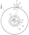
- a heat exchanging apparatus in accordance with a first embodiment of the invention is illustrated in Fig. 1 and Fig. 2.
- a heat convecting unit 2 through which the fluid effluent E is flowed, is disposed within an open reservoir or heat exchanging reservoir or tank 1 containing a prescribed bathing fluid F at the desired temperature.
- a prescribed bathing fluid F at the desired temperature.
- multiple small diameter coils arranged in parallel spirals 2c between an inlet tubing 2a and an outlet tubing 2b has been illustrated in Fig. 3.
- the heat convecting unit 2 is mounted on a sliding system 3 constituted from a support mast 4 solidly fixed in the center of the bottom 1a of tank 1, and a heat convecting unit supporting frame 5.
- the support frame 5 is a cylindrical frame with a top 5a and a bottom 5b joined by vertical beams 5c around which the coils 2c of the disposable heat convecting unit 2 is placed and secured, coaxially movable and fixed to the mast 4 by the holding means 6.
- the holding means 6 is fixedly attached to 5a on one hand, and movably attached to the mast 4 by its C-clamp 6a which is secured at the desired level by a bolt 6b. Accordingly the sliding system 3 allows to move the support frame 5 up or down along the support mast 4 and fix it at the desired level by tightening the bolt 6b.
- the central and coaxial location of the support mast 4 in relation to the tank 1 and coils 2c lends itself to using the mast 4 not only as a supporting mast, but also as an effective bath fluid disperser 7 by using a tubular structure with multiple fluid ejecting side holes 7a along the immersed portion of the mast that will eject the bath fluid forcefully towards the coils 2c that come in close apposition.
- the tank 1 is large enough to contain sufficient amounts of bath fluid and the cooling (refrigerating unit or simply prefabricated ice) or warming source(s).
- a circulating device 9 for pumping the bath fluid from the reservoir into the bath fluid disperser 7 has been incorporated.
- a pump 9a is provided for drawing bath fluid through an inlet tube 9b attached to an opening made in the bottom 1a of the tank 1 and pumping it into the fluid disperser 7 through an outlet tube 9c.
- the bath fluid rushes through the ejecting holes 7a creating motion of the bath fluid surrounding the coils 2c, thus forcing the bath fluid to circulate which will increase dissipation of the temperature, i.e., efficiency of the heat exchange.
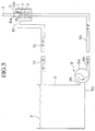
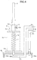
- Fig. 5, Fig. 6 and Fig. 7 illustrate second, third and fourth embodiments of this invention, respectively, in which the heat exchanging reservoir 1 has been made just big enough to house the heat convecting unit for portability, and the bulk of the bath fluid as well as the heat source (refrigerating unit or prefabricated ice, or warming device) have been disposed in a separate large tank, the bath fluid being circulated between the two reservoirs.
- the heat exchanging reservoir 1 has been made just big enough to house the heat convecting unit for portability, and the bulk of the bath fluid as well as the heat source (refrigerating unit or prefabricated ice, or warming device) have been disposed in a separate large tank, the bath fluid being circulated between the two reservoirs.
- the heat exchanging reservoir 1 has the economic open configuration for its easy construction according to the previous description, but could be one with a totally enclosed configuration in which the heat convecting unit could be slid in or out of the encasing reservoir as means to control the extent of immersion but maintaining water tightness to allow circulating the bath fluid (not illustrated because of the cost and complexity involved in its design).
- the heat exchanging reservoir 1 and the heat convecting unit (that portion with the array of arrows indicating the perfusate pathway coming from or leading to E) have been incorporated in a single enclosed complex (represented by the solid line) that could be made either with disposable material for single use or resterilizable material for multiple use.
- the means to control the area of the heat convecting unit that comes in contact with the bath fluid is provided by subdividing the bath fluid pathway (represented by the wavy arrows) portion of the complex unit in a number of chambers through which the bath fluid is flowed individually in a controllable manner using valves 17a disposed upstream each of the branches of the detachable bath fluid distributing inlet and outlet manifolds 17 (one dotted line components) equivalent to the disperser 7, and a one way air valve 20 to allow emptying of each of the excluded bath fluid pathway chambers.
- the level of the bath fluid is controllable by changing the level of the drainage port using a draining manifold 17 with multiple controllable ports by similar valves 17a and the one way air valve 20, or by a height controllable siphon type port instead of a multiple draining manifold (not illustrated).
- a large main tank 8 has been designed to hold enough bath fluid and ice, and in addition obligatory means 9 to circulate the bath fluid between the tank 8 and the tank 1 have been provided.
- the pump 9a draws bath fluid from the main tank 8 through the inlet tube 9b connected to an opening in the bottom portion 8a of the main tank 8, and pumps it through the outlet tube 9c into the mast 4/disperser 7 or distributing manifold 17 of the heat exchanging reservoir 1, so that the fluid is forcefully dispersed via the side holes 7a, or the active branch(es) controlled by the valves 17a of the distributing manifold 17 creating motion of the bath fluid surrounding the coils 2c of the heat convecting unit 2 or straight tubes 12a, and returned to the main tank 8 via a drainage tube 10.
- the drainage tube 10 is connected to the overflow opening disposed high enough in the lateral wall of the tank 1 to allow full immersion of the heat convecting unit 2 in the bath fluid in the open reservoir configuration as depicted in Fig. 5, or to a multiple ports draining manifold in the closed reservoir configuration as in Fig. 6 and Fig. 7.
- the connection of tube 9b is preferably made to the bottom of the tank 8 to draw the coldest bath fluid.
- the above embodiments use prefabricated ice as cooling source, but complex and sophisticated refrigerating or heating devices, such as those used in conventional heat exchangers, could be incorporated in the main tank 8 to serve as heat sources for providing the desired temperature of the bath fluid F.
- the temperature of the effluent E exiting the heat convecting unit 2 of the heat exchanging apparatus with the above embodiments can be controlled easily by loosening the bolt 6b of the holding means 6, sliding up or down the support frame 5 to the level where the desired temperature downstream the unit 2 is obtained and fixing it at that new position by tightening the bolt 6b of the first and second embodiments illustrated in Fig. 1, 2 or 5.
- the branch(es) of the fluid dispersing or distributing manifold 17 is(are) individually controlled using their respective valve 17a to shut the bath fluid flow and let the air in via the one way air valve 20 to empty the chamber(s) to be excluded, thus controlling the extent of immersion of the heat convecting unit 12.
- the draining port valve(s) 17a to the desired bath fluid level as well as the one way air valve are open, thus emptying part of the reservoir and controlling the extent of immersion of the heat convecting unit.
- temperature control could be accomplished by adjusting the temperature of the bath fluid in the main tank 8, it is simpler to keep enough ice in the main tank 8 to maintain the bath fluid temperature as close to the constant ice-melting temperature, and the effluent temperature control achieved by changing the extent of immersion of the heat convecting unit 2 or 12, i.e., by adjusting the effective heat convecting surface area in contact with the heat dissipating fluid.
- Additional minor or fine effluent E temperature control can be effected by adjusting the rate of turnover or flow rate of the bath fluid contacting the heat convecting unit 2 or 12 which determines the heat carrying capacity of the system by controlling the rate of the pump 9a.
- controlling the effluent temperature is reduced to the rather simple maneuver of adjusting the height of the holder 6 or the number of active bath fluid dispersing branches or the draining ports of the manifold 17.
- the embodiments of the apparatus are rather simple, not requiring complex, sophisticated and expensive devices to achieve it.
- the heat convecting unit 2 made out of multiple small tubes in parallel allows maximizing the heat convecting surface area, at the minimum cost of priming volume and pressure drop across the unit.
- the effluent temperature could almost be predicted if effluent E flows and the temperature of the effluent at the inlet of the unit 2 are known based on the extent of heat convecting unit immersed in the bath fluid, and final adjustments be made very simply by either fine control of the height of the holder 6, or altering the number of active branches of the manifold 17, and/or the bath fluid pump 9a rate.
- the use of the embodiment according to claim 4 allows easy portability of the heat convecting unit 2 or 12 portion of the apparatus to bring it close to the patient for example.
- the cooling temperature range usually required for medical uses can be provided with water or water based heat dissipating solutions, the use of prefabricated ice to cool the water of the bath fluid becomes highly practical. For warming, the use of hot water is also the simplest and cheapest means.
- Fig. 4 illustrates the simplest unit 12 in which multiple segments of straight tubes 12a are bundled and joined in parallel by means of two hollow collecting or distributing end plates 12b, one end 12c being connected to the inlet tube, and the other end 12d, disposed parallel to 12c for easy maneuverability, to the outlet tube.
- the rigid nature of the metallic tubes lends to their use for the construction of disposable or reusable heat exchanging complex units with multiple bath fluid chambers as that illustrated in Fig. 6.
- the heat convecting pathway(s) could be of the convoluted spirals, corrugated sheets or any other configuration known to increase the effective heat convecting surface area.
- the two-dotted line components of Fig. 1 represent a servo-control mechanism to maintain the effluent at a predetermined temperature, by adjusting the height of the support frame 5 with a somewhat more complex and automated mechanism.
- a sensor 14 to monitor the effluent temperature downstream to the heat convecting unit 2 that feeds the information to a microprocessor control unit 16 that in turn activates a motorized drive device 15 to move up or down the heat convecting unit supporting frame 5 to control the extent of its immersion in the bath fluid F thus adjusting the effective heat convecting surface area of the unit 2, and also obviates the need for manual fixing of holder 6 with the bolt 6b.
- a winding mechanism 15b has been illustrated in Fig.
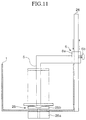
- FIG. 8 A fifth embodiment of this invention is illustrated in Fig. 8, in which components with the same or similar function to those already described have been identified with the same numbers and their explanation is omitted. Accordingly the mast/disperser 4/7 has been fixed in the center of a portable base 18 which is constituted by a plate 18b and supporting feet 18a that allows accommodating the tube 9c beneath the plate 18b. The mast/disperser 4/7 pierces the center of the base plate 18b to be connected to tube 9c, and the tube 9b which is the other arm of the means to circulate the bath fluid has been fixed at the periphery of the plate 18b with the opening facing the bottom of the tank.
- a portable base 18 which is constituted by a plate 18b and supporting feet 18a that allows accommodating the tube 9c beneath the plate 18b.
- the mast/disperser 4/7 pierces the center of the base plate 18b to be connected to tube 9c, and the tube 9b which is the other arm of the means to circulate the bath fluid has been fixed at the perip
- tubes 9b and 9c are connected to the inlet and outlet of the pump 9a respectively which has been omitted from the Figure. Because these components are not attached to the tank itself, the heat exchanging components can be moved with ease and immersed into any big enough reservoir such as an ordinary bucket with iced water, thus making it a versatile device.
- This unit 12 is supported by the support bar 5 and held by the holder 6, in turn attached to the mast/disperser 14/7 to allow sliding up or down the entire unit 12 along the mast 14 and its fixing at the proper height.
- Each of the fluid dispersers 7 that pierces the bottom of the bath fluid tank and ultimately connect to tube 9c, the tube 9b whose inlet opens at the bottom of the tank 1, and the pump 9a constitute the bath fluid circulating system 9. Sliding the holder 6 up or down alongside the mast 14, will change the extent of immersion of the unit 12 in the bath fluid F from none to all.
- the apparatus could be constructed following the aspects of this invention outlined in Fig. 5, Fig. 6, Fig. 7 or Fig. 8 as well.
- the bath fluid disperser 7 has been eliminated, and instead a fluid stirrer 25 has been provided at the bottom of the tank 1, the propellers 25b being actuated via a shaft by a motor 25a located outside of the tank 1, or coupled by electromagnetic means which is not illustrated in the Figure.
- the mast 24 to provide support of the said heat convecting unit 2 or 12 is disposed on the lateral wall of the tank 1.
- the stirring propellers 25b are set in motion, the bath fluid will move in the same direction as the stirring propellers thus creating a flow of the bath fluid surrounding the heat convecting unit, increasing the heat exchanging efficiency.
- controlling the speed of rotation of the stirring propellers affords some degree of perfusate temperature control, similarly to controlling the pump rate of the bath fluid in previously described embodiments.
Landscapes
- Engineering & Computer Science (AREA)
- Physics & Mathematics (AREA)
- Thermal Sciences (AREA)
- Mechanical Engineering (AREA)
- General Engineering & Computer Science (AREA)
- Devices For Medical Bathing And Washing (AREA)
- Heat-Exchange Devices With Radiators And Conduit Assemblies (AREA)
Applications Claiming Priority (2)
| Application Number | Priority Date | Filing Date | Title |
|---|---|---|---|
| JP108578/93 | 1993-05-10 | ||
| JP10857893A JPH06323762A (ja) | 1993-05-10 | 1993-05-10 | 熱交換器 |
Publications (2)
| Publication Number | Publication Date |
|---|---|
| EP0624770A2 true EP0624770A2 (de) | 1994-11-17 |
| EP0624770A3 EP0624770A3 (de) | 1995-08-09 |
Family
ID=14488371
Family Applications (1)
| Application Number | Title | Priority Date | Filing Date |
|---|---|---|---|
| EP19930310369 Withdrawn EP0624770A3 (de) | 1993-05-10 | 1993-12-21 | Wärmeaustauschvorrichtung. |
Country Status (3)
| Country | Link |
|---|---|
| EP (1) | EP0624770A3 (de) |
| JP (1) | JPH06323762A (de) |
| CA (1) | CA2111660A1 (de) |
Cited By (3)
| Publication number | Priority date | Publication date | Assignee | Title |
|---|---|---|---|---|
| FR2790074A1 (fr) * | 1999-02-23 | 2000-08-25 | Gerard Marret | Installation pour le refroidissement ou le rechauffement d'un liquide, notamment de l'eau de mer |
| US6696092B2 (en) | 1992-02-07 | 2004-02-24 | Vasogen Ireland Limited | Endothelial lining effects and treatment of vasospastic disorders |
| EP2058617A1 (de) * | 2007-11-09 | 2009-05-13 | Hubert Goseling | Kochkessel zur Zubereitung von Lebensmitteln |
Families Citing this family (4)
| Publication number | Priority date | Publication date | Assignee | Title |
|---|---|---|---|---|
| JP2009008327A (ja) * | 2007-06-28 | 2009-01-15 | Eco Power:Kk | 液中熱交換器及び熱利用システム |
| JP2013002581A (ja) * | 2011-06-20 | 2013-01-07 | Tatsuno Corp | ガス充填システム |
| CN104482527B (zh) * | 2014-12-10 | 2016-06-08 | 广东电网有限责任公司电力科学研究院 | 保证scr安全烟温的锅炉省煤器受热面换热面积的调节系统和方法 |
| JP2017020667A (ja) * | 2015-07-07 | 2017-01-26 | 大陽日酸株式会社 | 熱交換器 |
Family Cites Families (3)
| Publication number | Priority date | Publication date | Assignee | Title |
|---|---|---|---|---|
| JPS5231577A (en) * | 1975-06-26 | 1977-03-10 | Babcock Hitachi Kk | Dust-like waste matter disposal device |
| US4306018A (en) * | 1980-06-26 | 1981-12-15 | The Board Of Regents Of The University Of Nebraska | Method of gas-heat exchange |
| JPS6091110A (ja) * | 1983-10-25 | 1985-05-22 | 三井造船株式会社 | 蒸気温度の制御方法 |
-
1993
- 1993-05-10 JP JP10857893A patent/JPH06323762A/ja active Pending
- 1993-12-16 CA CA 2111660 patent/CA2111660A1/en not_active Abandoned
- 1993-12-21 EP EP19930310369 patent/EP0624770A3/de not_active Withdrawn
Cited By (3)
| Publication number | Priority date | Publication date | Assignee | Title |
|---|---|---|---|---|
| US6696092B2 (en) | 1992-02-07 | 2004-02-24 | Vasogen Ireland Limited | Endothelial lining effects and treatment of vasospastic disorders |
| FR2790074A1 (fr) * | 1999-02-23 | 2000-08-25 | Gerard Marret | Installation pour le refroidissement ou le rechauffement d'un liquide, notamment de l'eau de mer |
| EP2058617A1 (de) * | 2007-11-09 | 2009-05-13 | Hubert Goseling | Kochkessel zur Zubereitung von Lebensmitteln |
Also Published As
| Publication number | Publication date |
|---|---|
| CA2111660A1 (en) | 1994-11-11 |
| EP0624770A3 (de) | 1995-08-09 |
| JPH06323762A (ja) | 1994-11-25 |
Similar Documents
| Publication | Publication Date | Title |
|---|---|---|
| AU2010200720B2 (en) | Infusion fluid heat exchanger and cartridge | |
| US5269749A (en) | Heat exchange device for inducing cardioplegia | |
| US4894342A (en) | Bioreactor system | |
| US4891483A (en) | Heating apparatus for hyperthermia | |
| US7137261B2 (en) | Systems and methods for freezing, mixing and thawing biopharmaceutical material | |
| US4427009A (en) | Integrated cardioplegia delivery system | |
| KR20090080090A (ko) | 온열화학치료를 위한 시스템 | |
| WO1997016213A2 (en) | Extracorporeal blood oxygenation system having integrated blood pump, heat exchanger and membrane oxygenator | |
| JPH084626B2 (ja) | 自給式液投与装置 | |
| EP0624770A2 (de) | Wärmeaustauschvorrichtung | |
| AU2003278853A1 (en) | Systems and methods for freezing, mixing and thawing biopharmaceutical material | |
| US10178864B2 (en) | Portable organ perfusion system | |
| KR100786127B1 (ko) | 온도조절장치 | |
| EP0322733B1 (de) | Wärmeleitungsvorrichtung | |
| US5466603A (en) | Temperature regulated hybridization chamber | |
| US5337806A (en) | Method and device for heating or cooling a reaction flask | |
| EP0445079A2 (de) | Einrichtung zur Perfusion von Kardioplegie-Lösungen während einer Herzoperation | |
| EP3691712B1 (de) | Heizer/kühler für einen oxygenator | |
| SU738566A1 (ru) | Установка дл содержани водных организмов | |
| JPH0135317B2 (de) | ||
| SU942743A1 (ru) | Аппарат дл управл емой кардиоплегии | |
| CN119838655A (zh) | 一种控温装置 | |
| CN113710962A (zh) | 太阳能热系统 | |
| WO1993001846A1 (en) | Integrated cardioplegia system | |
| KR20260042666A (ko) | 음료 디스펜서 |
Legal Events
| Date | Code | Title | Description |
|---|---|---|---|
| PUAI | Public reference made under article 153(3) epc to a published international application that has entered the european phase |
Free format text: ORIGINAL CODE: 0009012 |
|
| AK | Designated contracting states |
Kind code of ref document: A2 Designated state(s): DE FR GB IT |
|
| PUAL | Search report despatched |
Free format text: ORIGINAL CODE: 0009013 |
|
| PUAF | Information related to the publication of a search report (a3 document) modified or deleted |
Free format text: ORIGINAL CODE: 0009199SEPU |
|
| AK | Designated contracting states |
Kind code of ref document: A3 Designated state(s): DE FR GB IT |
|
| D17D | Deferred search report published (deleted) | ||
| PUAL | Search report despatched |
Free format text: ORIGINAL CODE: 0009013 |
|
| AK | Designated contracting states |
Kind code of ref document: A3 Designated state(s): DE FR GB IT |
|
| STAA | Information on the status of an ep patent application or granted ep patent |
Free format text: STATUS: THE APPLICATION IS DEEMED TO BE WITHDRAWN |
|
| 18D | Application deemed to be withdrawn |
Effective date: 19960210 |