EP0624779A1 - Vorrichtung zur Messung der Winkellage eines Rotors - Google Patents
Vorrichtung zur Messung der Winkellage eines Rotors Download PDFInfo
- Publication number
- EP0624779A1 EP0624779A1 EP94201061A EP94201061A EP0624779A1 EP 0624779 A1 EP0624779 A1 EP 0624779A1 EP 94201061 A EP94201061 A EP 94201061A EP 94201061 A EP94201061 A EP 94201061A EP 0624779 A1 EP0624779 A1 EP 0624779A1
- Authority
- EP
- European Patent Office
- Prior art keywords
- signal
- coil
- rotor
- line
- output signal
- Prior art date
- Legal status (The legal status is an assumption and is not a legal conclusion. Google has not performed a legal analysis and makes no representation as to the accuracy of the status listed.)
- Granted
Links
- 239000013598 vector Substances 0.000 claims description 19
- 238000000034 method Methods 0.000 claims description 16
- 230000004044 response Effects 0.000 claims description 12
- 239000002131 composite material Substances 0.000 claims description 8
- 230000005540 biological transmission Effects 0.000 description 14
- 238000010586 diagram Methods 0.000 description 13
- 230000004907 flux Effects 0.000 description 11
- 230000008878 coupling Effects 0.000 description 9
- 238000010168 coupling process Methods 0.000 description 9
- 238000005859 coupling reaction Methods 0.000 description 9
- 230000006870 function Effects 0.000 description 8
- 230000000630 rising effect Effects 0.000 description 5
- 238000012360 testing method Methods 0.000 description 5
- 230000001419 dependent effect Effects 0.000 description 4
- 238000001514 detection method Methods 0.000 description 4
- 239000000463 material Substances 0.000 description 4
- 230000000694 effects Effects 0.000 description 3
- 238000004804 winding Methods 0.000 description 3
- 230000003247 decreasing effect Effects 0.000 description 2
- 238000013461 design Methods 0.000 description 2
- 230000001965 increasing effect Effects 0.000 description 2
- 238000004519 manufacturing process Methods 0.000 description 2
- 230000010363 phase shift Effects 0.000 description 2
- 229910000859 α-Fe Inorganic materials 0.000 description 2
- 239000000654 additive Substances 0.000 description 1
- 230000000996 additive effect Effects 0.000 description 1
- 229910045601 alloy Inorganic materials 0.000 description 1
- 239000000956 alloy Substances 0.000 description 1
- 230000008901 benefit Effects 0.000 description 1
- 239000003990 capacitor Substances 0.000 description 1
- 230000008859 change Effects 0.000 description 1
- 238000010276 construction Methods 0.000 description 1
- 238000012937 correction Methods 0.000 description 1
- 230000001351 cycling effect Effects 0.000 description 1
- 238000013016 damping Methods 0.000 description 1
- 239000012530 fluid Substances 0.000 description 1
- 239000011521 glass Substances 0.000 description 1
- 230000001976 improved effect Effects 0.000 description 1
- 230000001939 inductive effect Effects 0.000 description 1
- 230000000977 initiatory effect Effects 0.000 description 1
- 238000005259 measurement Methods 0.000 description 1
- 230000007246 mechanism Effects 0.000 description 1
- 239000004033 plastic Substances 0.000 description 1
- 229920003023 plastic Polymers 0.000 description 1
- 229920000642 polymer Polymers 0.000 description 1
- 230000009467 reduction Effects 0.000 description 1
Images





Classifications
-
- G—PHYSICS
- G01—MEASURING; TESTING
- G01D—MEASURING NOT SPECIALLY ADAPTED FOR A SPECIFIC VARIABLE; ARRANGEMENTS FOR MEASURING TWO OR MORE VARIABLES NOT COVERED IN A SINGLE OTHER SUBCLASS; TARIFF METERING APPARATUS; MEASURING OR TESTING NOT OTHERWISE PROVIDED FOR
- G01D5/00—Mechanical means for transferring the output of a sensing member; Means for converting the output of a sensing member to another variable where the form or nature of the sensing member does not constrain the means for converting; Transducers not specially adapted for a specific variable
- G01D5/12—Mechanical means for transferring the output of a sensing member; Means for converting the output of a sensing member to another variable where the form or nature of the sensing member does not constrain the means for converting; Transducers not specially adapted for a specific variable using electric or magnetic means
- G01D5/14—Mechanical means for transferring the output of a sensing member; Means for converting the output of a sensing member to another variable where the form or nature of the sensing member does not constrain the means for converting; Transducers not specially adapted for a specific variable using electric or magnetic means influencing the magnitude of a current or voltage
- G01D5/20—Mechanical means for transferring the output of a sensing member; Means for converting the output of a sensing member to another variable where the form or nature of the sensing member does not constrain the means for converting; Transducers not specially adapted for a specific variable using electric or magnetic means influencing the magnitude of a current or voltage by varying inductance, e.g. by a movable armature
- G01D5/204—Mechanical means for transferring the output of a sensing member; Means for converting the output of a sensing member to another variable where the form or nature of the sensing member does not constrain the means for converting; Transducers not specially adapted for a specific variable using electric or magnetic means influencing the magnitude of a current or voltage by varying inductance, e.g. by a movable armature by influencing the mutual induction between two or more coils
- G01D5/2046—Mechanical means for transferring the output of a sensing member; Means for converting the output of a sensing member to another variable where the form or nature of the sensing member does not constrain the means for converting; Transducers not specially adapted for a specific variable using electric or magnetic means influencing the magnitude of a current or voltage by varying inductance, e.g. by a movable armature by influencing the mutual induction between two or more coils by a movable ferromagnetic element, e.g. a core
-
- G—PHYSICS
- G01—MEASURING; TESTING
- G01R—MEASURING ELECTRIC VARIABLES; MEASURING MAGNETIC VARIABLES
- G01R5/00—Instruments for converting a single current or a single voltage into a mechanical displacement
- G01R5/14—Moving-iron instruments
- G01R5/16—Moving-iron instruments with pivoting magnet
-
- G—PHYSICS
- G01—MEASURING; TESTING
- G01R—MEASURING ELECTRIC VARIABLES; MEASURING MAGNETIC VARIABLES
- G01R7/00—Instruments capable of converting two or more currents or voltages into a single mechanical displacement
- G01R7/04—Instruments capable of converting two or more currents or voltages into a single mechanical displacement for forming a quotient
- G01R7/06—Instruments capable of converting two or more currents or voltages into a single mechanical displacement for forming a quotient moving-iron type
Definitions
- This invention relates to an instrument, for example an air core gauge, and to a method of providing feedback in an air core gauge.
- Typical analogue displays such as in vehicle instrument panels, utilised air core gauges to position pointers in relation to sensor values.
- the basic air core gauge mechanism includes a substantially circular disc of magnetised material fixed to a spindle and surrounded by at least two coils of wire, with at least one coil typically perpendicular to another of the coils.
- a magnetic field is produced exerting a force on the magnetised disc.
- the angular direction of the field produced by the coils primarily depends on the number of ampere-turns in each of the coils.
- the resultant magnetic field produced can be represented by the vector addition of the fields produced by each of the coils.
- the basic two coil air core gauge is typically driven by one of two methods.
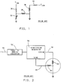
- coil 38 is biased to a fixed voltage V ign , through load resistor 34, while the voltage across coil 36 varies with a signal from sensor 32, a variable resistance sender forming with load resistor 30 a voltage divider between V ign and ground.
- V ign a fixed voltage
- load resistor 34 a variable resistance sender forming with load resistor 30 a voltage divider between V ign and ground.
- a signal on line 50 from a sensor (not shown), typically a signal with a frequency varying with a vehicle parameter, is converted to an analogue signal through circuit 52 and input into a sine/cosine drive circuit 56.
- the sine/cosine drive circuit 56 generates a signal on line 58 proportional to the cosine of the desired angle of deflection of the rotor and a signal on line 60 proportional to the sine of the desired angle of deflection of the rotor.
- Coils 62 and 64 in response to the signals on lines 58 and 60, develop magnetic fields with sine and cosine component magnetic vectors correlating to the desired pointer rotation.
- Various other methods which are not set forth herein are also used to drive air core gauges.
- Conventional drive methods for air core gauges are typically open loop systems in which actuation currents are applied to the coils without the use of any feedback information as to the actual pointer position to correct the values of the currents.
- Pointer direction errors can arise from many sources. Some of these sources include stray magnetic fields, such as from a nearby radio speaker magnet. To prevent any effect of stray magnetic fields on the gauge, a magnetic shunting enclosure (can) is typically mounted around the coils and rotor of the gauge. The shunting cans must be made from expensive alloys or heat treated to keep them from becoming magnetised by the coils, which would also cause errors.
- stray magnetic fields such as from a nearby radio speaker magnet.
- a magnetic shunting enclosure is typically mounted around the coils and rotor of the gauge. The shunting cans must be made from expensive alloys or heat treated to keep them from becoming magnetised by the coils, which would also cause errors.
- Pointer direction errors can arise from variations in the diameter of the wire used to wind the coils. As the diameter of the wire changes, the impedance changes, which may cause the current through the wire to change. Pointer direction errors can occur because of unbalanced or heavy pointers. Also, the damping fluid typically used in the air core gauges can cause a mechanical hysteresis which may lead to pointer errors.
- the present invention seeks to provide an improved instrument, such as an air core gauge.
- the instrument may be a general position sensor.
- the invention uses a newly discovered phenomenon which runs against knowledge conventionally applied by those skilled in the air core gauge art. Instead of treating the magnetic rotor of the air core gauge as an air gap as is conventionally done by those skilled in the art, the magnetic rotor is used for electronically determining the rotational position of the spindle using a magnetic coupling phenomenon of the magnetic rotor.
- the two coils are mounted substantially perpendicularly to each other and have very little magnetic coupling.
- the magnetic spindle of the air core gauge "links" the two coils, encouraging magnetic coupling in a manner dependent upon the relative position of the poles of the magnetic spindle.
- An alternating current input signal is placed on one coil and is variably coupled, through the rotor, to the other coil where an AC output signal develops.
- the degree of coupling that is the ratio between the input and the output signals, is dependent upon the rotational position of the rotor.
- a measurement of the output signal or the ratio between the input and output signals, can then be used as an indication of the rotational position of the rotor and therefore the position of a component to which the rotor is attached.
- the preferred implementation is used with an air core gauge.
- the air core gauge may be driven in a conventional manner by a drive signal.
- An AC input signal is superimposed onto the drive signal for one of the coils of the gauge.
- the AC input signal is at a frequency high enough that it does not interfere with the DC operation of the gauge.
- An AC output signal is developed from another coil, depending upon the rotational position of the rotor and used in feedback control to adjust the drive signal based upon the positional error of the rotor, if any.
- the AC output signal has an independent slope/magnitude or an independent phase/magnitude relationship for every rotational position between zero and 90 degrees, and an independent phase/magnitude/slope relationship for every rotational position between zero and 180.
- the benefit of this implementation is that it may be used to provide compensation for the various causes of pointer position error, since the drive signal may be responsively adjusted until the pointer position error equals zero.
- the apparatus comprises at least two coils which, when electric current flows therethrough, create a magnetic field acting on a rotatably mounted rotor.
- Means for creating an AC input signal is coupled to one of the coils and an AC output signal is developed on another of the coils in relation to the rotational position of the rotor.
- a method of providing feedback comprises applying an AC signal to one of at least two coils of the apparatus and developing an AC output signal on another coil in relation to the rotational position of a magnetic rotor.
- air core gauge 411 contains coils 412 and 414 which represent two windings of wire typically found in an air core gauge.
- the two windings are typically wound around perpendicular axes, coil 412 being wound around the O-D axis and coil 414 being wound around the B-F axis.
- the magnetic rotor 410 of the gauge is typically a disc shaped magnet having North and South poles 416 and 418 as shown.
- the flux characteristics of a two pole magnetic disc magnet, such as rotor 410, are shown as flux lines 420 in Figure 4.
- Coils 412 and 414 of the gauge 411 may be charged with a normal rotation drive signal to affect an angular rotation of the rotor 410.
- Coil 412 is additionally coupled to an AC signal source so that an AC input signal is superimposed onto the portion of the drive signal in coil 412. If coils 412 and 414 are perfectly perpendicular, there is no magnetic coupling of the AC input signal from coil 412 to 414.
- rotor 410 has a magnetic flux linkage to each coil, and hence provides a magnetic flux linkage between coils 412 and 414, inducing a coupled AC output signal (referred to below as the "AC output signal”) on coil 414 in response to the AC input signal on coil 412. Since the rotation drive signal is substantially DC, it does not cause signal coupling between coils 412 and 414.
- the flux linkage between coil 412 and rotor 410 is proportional to sin(i) , where i is the angle between North pole 416 (or South pole 418) and a line drawn through points B and F.
- the flux linkage between coil 414 and rotor 410 is proportional to sin(j) , where j is the angle between North pole 416 (or South pole 418) and a line drawn through points D and O. Since magnetic fluxes are additive vectors, rotor 410 links the two coils with a flux linkage proportional to sin(i)sin(j) .
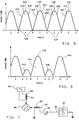
- FIG. 5 illustrates, relative to the angle of rotation of rotor 410, the magnitude of the AC output signal in coil 414 for an ideal gauge with perfectly perpendicular coils and a perfectly symmetrical magnetic rotor.
- curve 430 represents the magnitude of the AC output signal verses the angle of rotation.
- the magnitude 430 has four minimums 428, four maximums 422, four periods of positive slope 424 and four periods of negative slope 426.
- curve 430 has four equal lobes, 434, 436, 438 and 440.
- the minimums 428, where the coupled AC output signal is virtually zero, occur at points O, B, D and F, which are 90 degrees apart and correspond to the position of the North and South poles 416 and 418 when they are parallel to either of the axes of coils 412 or 414.
- the maximums 422 of the magnitude in the AC output signal occur at points A, C, E, and G and are 90 degrees apart and ideally 45 degrees from each adjacent minimum 428.
- Figure 6 represents a magnitude curve 432 of the AC output signal in a non-ideal gauge. If, for example, coils 412 and 414 are not exactly perpendicular, the four lobes 442, 444, 446 and 448 of the curve will not be equal. The four minimums may be shifted so that they are not exactly 45 degrees from the adjacent maximums. Additionally if the magnetic rotor is not exactly symmetrical, as in one pole having a higher flux density than the other pole, then the four lobes of the curve 432 will be unequal and the minimums may be shifted as shown. Although the lobes are unequal and the minimums are shifted, lobes 442 and 446 are equal to each other in height and width and lobes 444 and 448 are equal to each other in height and width.
- circuitry connected to the gauge coils Another factor that can affect the characteristics of the AC output signal is the circuitry connected to the gauge coils. If the circuitry implemented causes a phase shift in the AC signal the minimums may be shifted and the lobes may become uneven as shown in Figure 6.
- the embodiment of apparatus shown includes an AC signal source 80, coils 82 and 88, and a magnetic rotor 86.
- the coils 82 and 88 are placed so that if each coil has electric current flowing therethrough, a magnetic field is produced by each coil, parallel to lines 84 and 90, in immediate proximity to rotor 86.
- the preferred implementation is to mount the coils 82 and 88 so that if they are flowing with electric current, the magnetic fields produced by each coil are substantially perpendicular.
- the magnetic rotor 86 comprises a two pole magnet, is preferably a round disc and is rotatably mounted by any suitable means on an axis fixed relative to coils 82 and 88.
- the rotor 86 is mounted so that its rotational position varies with a measurable parameter. Examples include mounting rotor 86 on a wheel to sense the position of the wheel, or on a steering wheel shaft to sense steering wheel position, or using the rotor as the rotor of an air core gauge to sense the position of the gauge pointer.
- AC signal source 80 supplies an input AC signal to coil 82, which tends to generate magnetic fields through coil 82 parallel to arrow 84.
- the frequency of the AC signal is preferably between 20 and 40 Khz, high enough so as not to generate audible noise in coil 82 and low enough so as not to generate significant radio frequency interference. Although 20 to 40 Khz is the preferred range, other frequency ranges may be used.
- the AC input signal may be summed with any other signal applied to coil 82.
- the magnetic fields generated by coil 82 are coupled by magnet 86 to coil 88, causing an AC output signal to be developed in coil 88.
- magnet 86 can induce coupling between the two coils 82 and 88 in relation to the rotational position of magnetic rotor 86.
- the magnitude and phase of the AC output signal developed in coil 88 varies.
- the range of the ratio of the AC output signal magnitude to the AC input signal magnitude varies depending upon the position of the coils.
- the broadest range of output signal to input signal ratio is achieved if coils 82 and 88 are substantially perpendicular to each other.
- the phase of the AC output signal may be the same as the phase of the input signal or opposite, having a 180 degree phase shift.
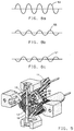
- Figures 8a, 8b and 8c show an AC input signal 53, an example AC output signal 55 in phase with input signal 53, and an example AC output signal 57 having a phase opposite to that of the input signal 53.
- the AC output signal developed in coil 88 can be detected by various means across coil 88, for example between line 92 and ground, and may be used for a variety of purposes as an indication of the rotational position of rotor 86.
- a simple implementation of means of detecting the AC output signal is shown in Figure 7, where the signal on line 92 may be coupled to line 96, the input of AC signal meter 94, which can display the position of rotor 86 through movement of a pointer, in response to the magnitude of the AC signal on line 92.
- Figure 9 shows an air core gauge incorporating an embodiment of rotor.
- the gauge shown has coils 10 and 12, coil 10 is perpendicular to and cross wound over coil 12 as shown, both coils being wound around bobbin 11, which is typically constructed of plastics material.
- magnetic rotor 86 within the windings of both coils of the gauge is magnetic rotor 86, here a two pole magnet of the preferred round cylinder shape.
- the magnetic rotor 86 is preferably constructed from a material such as a polymer bonded ferrite, glass ferrite, AlnicoTM, or any other equivalent material and magnetically charged into a permanent magnet.
- the rotor 86 is affixed to spindle 18, which is rotatably mounted within the bobbin 11.
- Pointer 16 is affixed to the end of the spindle 18 so that the pointer 16 moves as the spindle rotates.
- the gauge may have a pointer return means (not shown), such as a spring, biasing magnet, or a weight, so that the pointer returns to a predetermined position when no current flows through coils 10 and 12.
- substantially DC electric current is applied to coils 10 and 12, which create magnetic fields in response to the current through the coils.
- the magnetic fields add together forming a composite magnetic field, with a composite magnetic vector, with which magnetic rotor 86 rotates to align itself.
- Figure 10 is an example vector diagram pertaining to the operation of the gauge shown in Figure 9.
- one of the coils creates a magnetic vector 78 in a first direction 72
- the other coil creates a magnetic vector 74 in a second direction 70.
- the resultant magnetic vector with which the rotor aligns itself is vector 76, of which vectors 74 and 78 are component vectors.
- the gauge of Figure 9 is preferably connected into the circuit of Figure 11 as shown.
- an input signal is supplied on line 146 from a sensor (not shown).
- the signal may be any type of input signal, but for purposes of this description is assumed to be a varying voltage signal, such as from sender 32, and may be filtered if necessary.
- A/D converter 142 converts the signal to a digital signal, which is output on bus 148.
- the digital signal on bus 148 is fed to one side of a comparator/error amplifier 122.
- the other input of the comparator/error amplifier 122 is fed with a signal on line 143 representing the current position of the rotor 86 (and pointer 16).
- the comparator/error amplifier 122 in response to the signals on buses 143 and 148, outputs a signal to the sine/cosine generator 110, which comprises the means for supplying substantially DC current.
- the sine/cosine generator 110 adjusts its output signals on lines 112, 114 and 118, 126, in response to the error signal from the comparator/error amplifier 122.
- the sine/cosine generator 110 supplies a voltage between lines 112 and 114 which is a substantially DC signal and represents the sine of the angle of the composite magnetic vector which is desired to be generated by coils 10 and 12.
- the sine/cosine generator supplies a voltage between lines 118 and 126 which is a substantially DC signal and represents the cosine of the angle of the composite magnetic vector which is desired to be generated by coils 10 and 12.
- the signal on line 114 is coupled, through unity gain amplifier 120, to one terminal of coil 12 of the gauge.
- the signal on line 112 is coupled through dropping resistor 128 and unity gain amplifier 130 to the other terminal of coil 12 of the gauge.
- the signal on line 118 is coupled through unitary gain amplifier 116 to one terminal of coil 10.
- the signal on line 126 is coupled through unitary gain amplifier 140 and inductor 134 to the other terminal of coil 10.
- Inductor 134 acts as a low pass filter and has virtually zero effect on the signal supplied by lines 118 and 126.
- AC signal generator 136 generates on line 150 an AC signal at, for example, 20 Khz.
- the AC signal on line 150 is coupled through capacitor 132 to line 129 and from there, through amplifier 130, to coil 12.
- Resistor 128 isolates the dc level signal on line 129 from the output of sine/cosine generator 110.
- the resultant current through coil 12 is a sine wave signal with a varying DC offset, the DC offset being controlled by the voltage difference between lines 112 and 114.
- quadrant detection can be implemented by sensing the drive current in coils 10 and 12. Quadrant detection assumes that the rotor is in the quadrant to which it is driven.
- the quadrant information can be used together with the magnitude, phase and/or slope information to determine rotor position.
- the AC signal developed across coil 10 is filtered by filter 124.
- the centre point of filter 124 may be designed to track the frequency of the AC signal generator 136 so that AC signal generator 136 need not be precise.
- line 150 may be fed to filter 124. Construction of filter 124 may be easily accomplished by one skilled in the art.
- the filtered signal output by filter 124 appears on line 152 and is fed into position circuitry 138.
- the signal developed by the AC signal generator 136 on line 150 is also fed into the position circuitry 138.
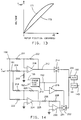
- the position circuitry 138 is shown in Figure 12 and comprises peak detectors 162 and 174, memory 180, D/A converter 182, ratio circuits 168 and 172, and A/D converter 160.
- the signals on lines 152 and 150 are input to peak detectors 162 and 174, respectively.
- the detected peak signals are output on lines 164 and 176 and input into ratio circuitry 172, which takes the ratio of the peak amplitude signal from coil 10 over the peak amplitude signal from coil 12. The ratio is used to eliminate the effects of the varying sine wave amplitudes due to fluctuations in the power supply for AC signal generator 136.
- the ratio developed in ratio circuitry 172 is output on line 170 and input into ratio circuitry 168.
- Ratio circuitry 168 generates a ratio of the output of ratio circuitry 172 to the maximum ratio, and supplies this on line 178.
- the maximum ratio on line 178 is developed either from a test routine which may be performed during manufacture of the vehicle instrumentation, or during an initiation cycle of the circuitry, which may be run each time the vehicle is started.
- the test routine sends a test signal on line 146 ( Figure 11) which varies from the minimum input signal to the maximum input signal, cycling the gauge and rotor 86 through all pointer positions.
- the ratio of the signal on lines 152 and 150, on line 170 is monitored, for example through peak detector 184.
- the peak of the signal on line 170 during the test routine is the maximum ratio and is converted into a digital signal, for example through A/D converter 186, and programmed into memory 180, with a programming pulse on line 144. If the test routine is only run during vehicle manufacture, peak detector 184 and A/D converter 186 may be external circuits.
- the maximum ratio, stored in memory 180, is supplied on line 178 via D/A converter 182.
- the signal on line 166, the output of the ratio circuitry 168, is equal to that on line 181 (V ref ) when the signal on line 170 is equal to that on line 178; is generally less than that on line 181 when the signal on line 170 is less than that on line 178; and is equal to zero when the signal on line 170 is equal to zero.
- the signal on line 166 is fed into A/D converter 160, then to function generator 161 and output on bus 143.
- the signal on bus 143 is both a measure of the AC output signal and an indication of rotor 86 (and pointer 16) position (rotor position signal).
- Bus 143 supplies the rotor position signal to the comparator/error amplifier 122 ( Figure 11), which alters the substantially DC sine and cosine drive signals to coils 10 and 12 if the signal on bus 143 indicates improper positioning of rotor 86.
- Figure 13 illustrates the magnitude of the output signal on line 166 (reference 171) in relation to the rotational position of the rotor.
- Function generator 161 may comprise a look-up table to linearise the signal on line 166, as indicated by line 173.
- An independent pointer position signal for 90 degrees of pointer rotation may be provided by a circuit which incorporates phase discrimination circuitry between the input sine wave signal on line 150 and the output sine wave signal on line 152.
- Figure 14 illustrates circuitry which, when combined with the circuitry of Figure 12, enables closed loop position control for the first 90 degrees of pointer rotation.
- circuitry in Figure 14 is coupled between line 166 of Figure 12 and A/D converter 160.
- apparatus incorporating the circuitry in Figure 14 can detect both magnitude and phase of the gauge feedback signal and provides an output signal with an independent value for the first 90 degrees of rotation of the air core gauge.
- the input and output sine wave signals on lines 150 and 152 are input to phase discrimination circuitry 210, which outputs a signal on line 192 which is high when the two signals are in-phase and low when the two signals are out-of-phase.
- the signal on line 166 which is the ratio of the input to output magnitudes (Figure 12), is fed to the circuitry relating to amplifiers 206 and 224.
- Line 181 is the same voltage reference signal to which A/D converter 186 and D/A converter 182 in Figure 12 are referenced.
- the output of amplifier 206 on line 212 equals V REF - V166.
- Lines 181 and 166 are also input through summing amplifier 224 and associated resistors 218, 220 and 222, all of equal resistance.
- Amplifier 224 provides an output signal on line 225 equal to -(V REF + V166). Since the summing amplifier 224 inverts the sum of the signals on lines 166 and 181, inverting amplifier 230 and resistors 226 and 228 are used to re-invert the signal and output the signal on line 231 equal to V REF + V166.
- the phase discrimination signal on line 192 controls transmission gate 214 directly and controls transmission gate 232 via inverter 216.
- Transmission gates 214 and 232 couple either the signal on line 212 (V REF - V166) or the signal on line 231 (V REF + V166) to line 200, depending on whether the input and output signals on lines 150 and 152 ( Figure 12) are in-phase or out-of-phase.
- the signal on line 200 is then fed to A/D converter 160 and then to function generator 161, which provides, on bus 143, a digital signal with an independent value for each position the first 90 degrees of rotation of the air core gauge.
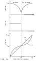
- Figure 15 illustrates the output signals on lines 166, 192 and 200 for the circuitry show in Figure 14.
- the output signal on line 200, curve 177 has an independent value for each position of the first 90 degrees of rotation of the air core gauge.
- the signal on line 200 is generally below V REF when the sine wave input and output signals on lines 150 and 152 are in-phase, which occurs in the first 45 degrees of rotation, and the signal on line 200 is generally above the V ref when the sine wave signals on lines 150 and 152 are out-of-phase, which occurs between 45 and 90 degrees of gauge rotation.
- Curve 175 represents the output of function generator 161.
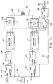
- Figures 16 and 18 illustrate circuitry which, when used with the circuitry in Figures 11 and 12 and when coupled between line 166 and A/D converter 160, provides an independent output signal for each position of the first 180 degrees of rotation of the rotor 86, allowing closed loop positional control of the rotor 86 for the first 180 degrees of rotation.
- the portion 305 of circuit shown in Figure 18 is for use with the circuitry shown in Figure 20 and allows closed loop control of rotor 86 position for complete 360 degrees of rotation of the rotor 86.
- the circuitry in Figure 12 determines the ratio of the input and output signals on lines 150 and 152 and provides the ratio signal on line 166.
- the circuitry in Figure 16 determines the direction of the respective slopes of the position input signal on line 146 and the output ratio on line 166 and provides an output signal on line 300 having a first state when the slopes of the signals on lines 146 and 166 are in the same direction (that is both slopes are positive or negative) and having a second state when the slopes of the signals on lines 146 and 166 are in opposite directions (that is one slope positive and the other slope negative).
- the circuitry shown in Figure 18 uses the amplitude ratio for signals on lines 150 and 152, the phase difference between the signals on lines 150 and 152 and the relative slope information from the circuitry shown in Figure 16 to provide an output signal on line 240 which has an independent value for each position of the first 180 degrees of rotation of the rotor 86.
- the positional input signal on line 146 is input to A/D converter 142 and the ratio signal on line 166 is input to A/D converter 274.
- Clock 234 provides a clock pulse on line 236 with a rising edge, responsive to which the A/D converters 142 and 374 lock in their respective input signals from lines 146 and 166.
- latches 238 and 240 latch in the previous A/D converter signals from A/D converters 142 and 274, respectively, providing to the A inputs of comparators 242 and 244 signals representing the magnitude of the values on lines 146 and 166, respectively, for the previous clock pulse and signals at the B inputs representing the values on lines 144 and 166, respectively, for the current clock pulse.
- the magnitude comparators 242 and 244 control flip-flops 248 and 250, respectively, so that each flip-flop outputs a logic high signal to XNOR gate 252 when the slope of the signals on lines 146 and 166 are increasing and the flip-flops 248 and 250 output logic low signals to XNOR gate 252 when the signals on lines 146 and 166 are decreasing.
- XNOR gate 252 receives either two high signals or two low signals from the flip-flops 248 and 250 when the slopes of the signals on lines 146 and 166 have the same direction.
- the signal on line 300 goes high when both the signals on lines 146 and 166 are rising and when both the signals on lines 146 and 166 are falling. Otherwise, line 300 is low.
- the second input to AND gate 256 receives a second input from the inverted clock pulse through inverter 246.
- AND gate 256 inhibits updating A/D converter 160 when both the signals on lines 146 and 166 are unchanging.
- Inverter 246 inverts the clock pulse so that A/D converters 142 and 274 can operate on the rising edge of the clock signal on line 236 and so that A/D converter 160, when not inhibited by NAND gate 254 and AND gate 256, operates on the falling edge of the signal on line 236. This provides time for magnitude comparators 242 and 244 to operate and stabilise before A/D converter 160 is updated.
- the input signal on line 240 for A/D converter 160 is provided by the circuitry described with respect to Figure 18.
- the output of A/D converter 160 is provided to a function generator 161, which may be an EEPROM look-up table or any other suitable type of function generator, to normalise the output of A/D converter 160 to amplifier 122 and/or the sine/cosine generator 110 in a manner known to those skilled in the art, if so desired.
- the timing diagram in Figure 17 illustrates the input signal on line 166, the phase signal on line 192, described below with reference to Figure 18, and the slope signal on line 300.
- the portion of the circuitry shown responds to the phase discriminator 210 output on line 192 and the slope signal on line 300 to generally add one V REF value (from line 181) to the ratio signal on line 166 for each 45 degree advance in the rotation of the rotor 86. Likewise, the circuitry subtracts one V REF value on line 181 from the ratio signal for each 45 degrees of rotor 86 rotation in the reverse direction.
- the output signal on line 240 for the first 180 degrees of rotation.
- the output signal on line 240 equals the value on line 166.
- the output signal on line 240 equals twice the reference voltage on line 181 minus the value of the signal on line 166.
- the output signal on line 240 equals twice the value of the reference signal on line 181 plus the value of the signal on line 166.
- the output signal on line 240 equals four times the value of the reference signal on line 181 minus the value of the signal on line 166.
- the ratio signal on line 166 is subtracted from the reference signal on line 181, provided via buffer amplifier 260, by amplifier 262 and associated resistors 264, 266, 268 and 270, all having equal resistances, so that the output of amplifier 262 equals V REF - V166, which is fed to transmission gate 274.
- the ratio signal on line 166 is fed to transmission gate 272.
- the output of the buffer amplifier 260 is fed to transmission gates 278 and 301 and all of the transmission gates are coupled to summing amplifier 284 via resistors 280, 286 and 288.
- Summing amplifier 284 includes associated resistor 282.
- the value of resistors 280, 282 and 286 are equal and the value of the resistor 288 is half that of 280, 282 and 286.
- the slope of the signal on line 300 controls transmission gate 272 to feed selectively the signal on line 166 to summing amplifier 284.
- Line 300 also controls transmission gate 274 via inverter 276 to selectively provide, via resistor 280, the signal V REF - V166 to summing amplifier 284.
- the signal from line 166 is coupled to amplifier 284 when the slope signal indicates that the signals on lines 146 and 166 have slopes of the same sign.
- the signal V REF - V166 is coupled to amplifier 284 when the signal on line 300 indicates that the slopes of the signals on lines 146 and 166 do not have the same sign.
- the signal V REF is selectively coupled to summing amplifier 284 via transmission gate 278, controlled by the signal on line 300 via inverter 276.
- Transmission gate 278 is controlled to couple V REF to amplifier 284 when the slope of the signal on line 146 is not of the same sign as the slope of the signal on line 166.
- inverter 302 activates transmission gate 301, coupling V REF , via resistor 288, to summing amplifier 284.
- Amplifier 312 and associated resistors 308 and 310 invert the output of amplifier 284, providing the signal on line 240 according to the illustration shown in Figure 19. As can be seen, for each position of the first 180 degrees of rotation of the rotor 86, the output signal on line 240 provides an independent output value.
- an independent output signal on line 240 is provided for each position of the rotor 86 during a complete 360 degrees of rotation.
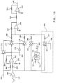
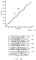
- the quadrant detection circuitry shown in Figure 20 detects if the position of the rotor 86 is in the first 180 degrees or the second 180 degrees and adds four times the reference voltage to the output signal on line 240 if the rotor 86 is in the second 180 degrees of rotation, effectively extending the output signal line 240 shown in Figure 19 in the manner shown in Figure 21.
- the circuit shown in Figure 20 is coupled to lines 112, 118 and 126 in Figure 11 and to line 192 in Figure 18.
- the signals on lines 112 and 118 that is the positive sine signal and negative cosine signal from sine-cosine generator 110, are input to differential amplifier 320 to provide a logic high output to AND gate 324 when the negative cosine signal is greater than the sine signal.
- the sine signal on line 112 and the cosine signal on line 126 are fed to differential amplifier 322, which outputs a logic high signal to an AND gate 326 when the cosine signal on line 126 is greater than the sine signal on line 112.
- the second input to AND gate 324 is controlled by the phase line 192 and the second input to AND gate 326 is controlled by the phase line 192 via inverter 328.
- AND gate 326 provides a high output signal when lines 152 and 150 are out-of-phase and when the signal level on line 112 is less than the signal level on line 126.
- AND gate 324 provides the high output signal when lines 152 and 150 are in-phase and when the signal on line 112 is less than the signal on line 118.
- the resultant output signal of OR gate 330 on line 306 is logic high when the rotational positional of the rotor 86 is greater than 180 degrees and logic low when it is less than 180 degrees.
- signal line 306 controls transmission gate 304 which couples the signal V REF to summing amplifier 284 via resistor 307, having a resistance value one-quarter of that of resistors 280, 282 and 286.
- the output signal on line 240 rises by a level of four times V REF .
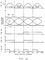
- the timing diagram in Figure 22 illustrates the signal on line 166 and the signals 400, 402, 404 and 406, which are the outputs of the sine-cosine generator 110 lines 112, 114, 118 and 126 respectively through 360 degrees of rotation.
- Figure 22 also illustrates the signal on line 306, the signal on line 192 and the signal on line 300. As can be seen, through 360 degrees of rotation, there is only one signal on line 240 for each position of the rotor 86.
- the position signal on bus 143 enables control of the pointer through feedback, as illustrated in the circuits described above. Since the pointer position is controlled through feedback, errors in the position of the pointer can be eliminated and gauge designs can be simplified. For example, there is no longer any need to shield against stray magnetic fields since feedback control enables corrections for errors induced by such stray fields.
- Figure 23 illustrates the steps of an embodiment of method implemented in the above described circuits, comprising the steps of applying a first DC signal to a first coil of a gauge (step 502), applying a second DC signal to a second coil of a gauge (step 504), superimposing an AC signal with the first DC signal (step 506), measuring an AC output signal developed across the second coil of the gauge (step 508), and altering at least one of the DC signals in response to the measured AC output signal (step 510).
- the zero position of the rotor 86 can be at any point, not just a maximum ratio point or a minimum ratio point. Different zero positions of the rotor 86 may be easily offset by varying the function of the function generator 161.
Landscapes
- Physics & Mathematics (AREA)
- General Physics & Mathematics (AREA)
- Measurement Of Length, Angles, Or The Like Using Electric Or Magnetic Means (AREA)
- Transmission And Conversion Of Sensor Element Output (AREA)
Applications Claiming Priority (2)
| Application Number | Priority Date | Filing Date | Title |
|---|---|---|---|
| US08/058,332 US5489842A (en) | 1993-05-10 | 1993-05-10 | Method and apparatus for determining the rotational position of a magnetic rotor relative to current carrying coils utilizing magnetic coupling between coils |
| US58332 | 1998-04-09 |
Publications (2)
| Publication Number | Publication Date |
|---|---|
| EP0624779A1 true EP0624779A1 (de) | 1994-11-17 |
| EP0624779B1 EP0624779B1 (de) | 1996-12-11 |
Family
ID=22016167
Family Applications (1)
| Application Number | Title | Priority Date | Filing Date |
|---|---|---|---|
| EP94201061A Expired - Lifetime EP0624779B1 (de) | 1993-05-10 | 1994-04-18 | Vorrichtung zur Messung der Winkellage eines Rotors |
Country Status (3)
| Country | Link |
|---|---|
| US (1) | US5489842A (de) |
| EP (1) | EP0624779B1 (de) |
| DE (1) | DE69401092T2 (de) |
Cited By (1)
| Publication number | Priority date | Publication date | Assignee | Title |
|---|---|---|---|---|
| DE19821462A1 (de) * | 1998-05-13 | 1999-11-25 | Balluff Gebhard Gmbh & Co | Vorrichtung und Verfahren zur berührungslosen Erfassung von ferromagnetischen Objekten |
Families Citing this family (4)
| Publication number | Priority date | Publication date | Assignee | Title |
|---|---|---|---|---|
| US5999108A (en) * | 1996-07-18 | 1999-12-07 | Hanneman; Charles K. | Avionics display pointer sensor |
| US5783939A (en) * | 1996-07-26 | 1998-07-21 | Delco Electronics Corporation | Stepper motor gauge calibration by AC feedback |
| US6326781B1 (en) * | 1999-01-11 | 2001-12-04 | Bvr Aero Precision Corp | 360 degree shaft angle sensing and remote indicating system using a two-axis magnetoresistive microcircuit |
| US9479014B2 (en) * | 2012-03-28 | 2016-10-25 | Acme Product Development, Ltd. | System and method for a programmable electric converter |
Citations (4)
| Publication number | Priority date | Publication date | Assignee | Title |
|---|---|---|---|---|
| FR1231825A (fr) * | 1959-04-16 | 1960-10-03 | Electronique Et D Automatique | Dispositif de contrôle et de commande de sécurité asservi à un organe situé dans un milieu d'accès difficile |
| US3045227A (en) * | 1958-01-27 | 1962-07-17 | Minas Giorgio | Electromagnetic devices for converting a movement of an electric value |
| US3828254A (en) * | 1973-08-06 | 1974-08-06 | Ford Motor Co | Magnetic gauge circuit |
| DE2432397A1 (de) * | 1973-07-06 | 1975-01-23 | Hitachi Ltd | Variabler induktor |
Family Cites Families (9)
| Publication number | Priority date | Publication date | Assignee | Title |
|---|---|---|---|---|
| US3113300A (en) * | 1959-11-12 | 1963-12-03 | Electro Mechanical Res Inc | Position sensing apparatus |
| NL273111A (de) * | 1961-01-03 | |||
| US3562740A (en) * | 1967-02-13 | 1971-02-09 | Bendix Corp | Rotary transformer nulling system |
| US3602811A (en) * | 1969-07-17 | 1971-08-31 | Gen Motors Corp | Electrical measuring device |
| US3946311A (en) * | 1973-06-11 | 1976-03-23 | Stewart-Warner Corporation | Air core gauge with expanded pointer range |
| JPH0677028B2 (ja) * | 1989-03-16 | 1994-09-28 | 矢崎総業株式会社 | 計器用ムーブメント |
| US5004976A (en) * | 1989-11-03 | 1991-04-02 | Chrysler Corporation | Wye winding radial air-core gauge system |
| US5059916A (en) * | 1990-01-08 | 1991-10-22 | National Semiconductor Corporation | Gauge driver for use with a remote sensor and having reduced offset potential response |
| US5309087A (en) * | 1992-09-08 | 1994-05-03 | Chrysler Corporation | Air core gauge, multi-frequency pulse width modulator system therefor |
-
1993
- 1993-05-10 US US08/058,332 patent/US5489842A/en not_active Expired - Fee Related
-
1994
- 1994-04-18 EP EP94201061A patent/EP0624779B1/de not_active Expired - Lifetime
- 1994-04-18 DE DE69401092T patent/DE69401092T2/de not_active Expired - Fee Related
Patent Citations (4)
| Publication number | Priority date | Publication date | Assignee | Title |
|---|---|---|---|---|
| US3045227A (en) * | 1958-01-27 | 1962-07-17 | Minas Giorgio | Electromagnetic devices for converting a movement of an electric value |
| FR1231825A (fr) * | 1959-04-16 | 1960-10-03 | Electronique Et D Automatique | Dispositif de contrôle et de commande de sécurité asservi à un organe situé dans un milieu d'accès difficile |
| DE2432397A1 (de) * | 1973-07-06 | 1975-01-23 | Hitachi Ltd | Variabler induktor |
| US3828254A (en) * | 1973-08-06 | 1974-08-06 | Ford Motor Co | Magnetic gauge circuit |
Cited By (1)
| Publication number | Priority date | Publication date | Assignee | Title |
|---|---|---|---|---|
| DE19821462A1 (de) * | 1998-05-13 | 1999-11-25 | Balluff Gebhard Gmbh & Co | Vorrichtung und Verfahren zur berührungslosen Erfassung von ferromagnetischen Objekten |
Also Published As
| Publication number | Publication date |
|---|---|
| DE69401092T2 (de) | 1997-04-03 |
| DE69401092D1 (de) | 1997-01-23 |
| US5489842A (en) | 1996-02-06 |
| EP0624779B1 (de) | 1996-12-11 |
Similar Documents
| Publication | Publication Date | Title |
|---|---|---|
| US6791217B2 (en) | Method and system for motor velocity measurement | |
| US6229299B1 (en) | System and method for computing the angular velocity and direction of a rotational body | |
| US5742160A (en) | Apparatus for determining angular position and rotational speed using a rotating magnet and a directional magnetometer | |
| EP0325787B1 (de) | Multidrehungs-Positionsgeber | |
| US7053602B2 (en) | Rotation sensor and method for detecting a rotation angle of a rotating member | |
| US4277751A (en) | Low-power magnetometer circuit with constant current drive | |
| US6346812B1 (en) | Conditioner circuit for magnetic field sensor | |
| US20030222642A1 (en) | Arrangement for determining the position of a motion sensor element | |
| US20250093220A1 (en) | Improved inductive torsion bar torque sensor | |
| BRPI0806373A2 (pt) | aparelho para prover um sinal relacionado com uma posição de um elemento acoplador | |
| JP2529960B2 (ja) | 磁気的位置検出装置 | |
| EP0624779B1 (de) | Vorrichtung zur Messung der Winkellage eines Rotors | |
| US4442609A (en) | Vehicle orientation detecting device for an automotive vehicle or another vehicle | |
| US4988944A (en) | Cross coil type instrument | |
| EP1752750A1 (de) | Magnetoelastischer Drehmomentwandler | |
| CA1231255A (en) | Coil system for inductive measurement of the velocity of movement of a magnetized body | |
| RU2075042C1 (ru) | Устройство для контроля датчиков угловой скорости | |
| EP0376095B1 (de) | Methode zur Messung des magnetischen Flusses und Gerät zur Anwendung dieser Methode | |
| EP1016852A1 (de) | Positionssensor | |
| JPH0230726Y2 (de) | ||
| US6384592B1 (en) | Apparatus for minimizing angular rotor position errors in an air core gauge | |
| JPS60162920A (ja) | 磁気感応素子を用いたレゾルバ−装置 | |
| JPH03255915A (ja) | 流量検出装置 | |
| SU1620844A1 (ru) | Устройство дл измерени расхода жидких и газообразных сред | |
| JP3920896B2 (ja) | リニア位置検出装置 |
Legal Events
| Date | Code | Title | Description |
|---|---|---|---|
| PUAI | Public reference made under article 153(3) epc to a published international application that has entered the european phase |
Free format text: ORIGINAL CODE: 0009012 |
|
| AK | Designated contracting states |
Kind code of ref document: A1 Designated state(s): DE FR GB IT |
|
| 17P | Request for examination filed |
Effective date: 19950517 |
|
| 17Q | First examination report despatched |
Effective date: 19950613 |
|
| GRAG | Despatch of communication of intention to grant |
Free format text: ORIGINAL CODE: EPIDOS AGRA |
|
| GRAH | Despatch of communication of intention to grant a patent |
Free format text: ORIGINAL CODE: EPIDOS IGRA |
|
| GRAH | Despatch of communication of intention to grant a patent |
Free format text: ORIGINAL CODE: EPIDOS IGRA |
|
| GRAA | (expected) grant |
Free format text: ORIGINAL CODE: 0009210 |
|
| ITF | It: translation for a ep patent filed | ||
| AK | Designated contracting states |
Kind code of ref document: B1 Designated state(s): DE FR GB IT |
|
| REF | Corresponds to: |
Ref document number: 69401092 Country of ref document: DE Date of ref document: 19970123 |
|
| ET | Fr: translation filed | ||
| PLBE | No opposition filed within time limit |
Free format text: ORIGINAL CODE: 0009261 |
|
| STAA | Information on the status of an ep patent application or granted ep patent |
Free format text: STATUS: NO OPPOSITION FILED WITHIN TIME LIMIT |
|
| 26N | No opposition filed | ||
| REG | Reference to a national code |
Ref country code: GB Ref legal event code: IF02 |
|
| REG | Reference to a national code |
Ref country code: GB Ref legal event code: 732E |
|
| REG | Reference to a national code |
Ref country code: FR Ref legal event code: TP |
|
| PGFP | Annual fee paid to national office [announced via postgrant information from national office to epo] |
Ref country code: IT Payment date: 20090422 Year of fee payment: 16 Ref country code: FR Payment date: 20090417 Year of fee payment: 16 Ref country code: DE Payment date: 20090420 Year of fee payment: 16 |
|
| PGFP | Annual fee paid to national office [announced via postgrant information from national office to epo] |
Ref country code: GB Payment date: 20090415 Year of fee payment: 16 |
|
| GBPC | Gb: european patent ceased through non-payment of renewal fee |
Effective date: 20100418 |
|
| REG | Reference to a national code |
Ref country code: FR Ref legal event code: ST Effective date: 20101230 |
|
| PG25 | Lapsed in a contracting state [announced via postgrant information from national office to epo] |
Ref country code: DE Free format text: LAPSE BECAUSE OF NON-PAYMENT OF DUE FEES Effective date: 20101103 |
|
| PG25 | Lapsed in a contracting state [announced via postgrant information from national office to epo] |
Ref country code: GB Free format text: LAPSE BECAUSE OF NON-PAYMENT OF DUE FEES Effective date: 20100418 Ref country code: IT Free format text: LAPSE BECAUSE OF NON-PAYMENT OF DUE FEES Effective date: 20100418 |
|
| PG25 | Lapsed in a contracting state [announced via postgrant information from national office to epo] |
Ref country code: FR Free format text: LAPSE BECAUSE OF NON-PAYMENT OF DUE FEES Effective date: 20100430 |