EP0624810A2 - Baugruppe für Glasfaserverbindung und Glasfaserstecker - Google Patents
Baugruppe für Glasfaserverbindung und Glasfaserstecker Download PDFInfo
- Publication number
- EP0624810A2 EP0624810A2 EP94107485A EP94107485A EP0624810A2 EP 0624810 A2 EP0624810 A2 EP 0624810A2 EP 94107485 A EP94107485 A EP 94107485A EP 94107485 A EP94107485 A EP 94107485A EP 0624810 A2 EP0624810 A2 EP 0624810A2
- Authority
- EP
- European Patent Office
- Prior art keywords
- stopring
- ferrule
- optical fiber
- flange
- face
- Prior art date
- Legal status (The legal status is an assumption and is not a legal conclusion. Google has not performed a legal analysis and makes no representation as to the accuracy of the status listed.)
- Granted
Links
Images




Classifications
-
- G—PHYSICS
- G02—OPTICS
- G02B—OPTICAL ELEMENTS, SYSTEMS OR APPARATUS
- G02B6/00—Light guides; Structural details of arrangements comprising light guides and other optical elements, e.g. couplings
- G02B6/24—Coupling light guides
- G02B6/36—Mechanical coupling means
- G02B6/38—Mechanical coupling means having fibre to fibre mating means
- G02B6/3807—Dismountable connectors, i.e. comprising plugs
- G02B6/3869—Mounting ferrules to connector body, i.e. plugs
-
- G—PHYSICS
- G02—OPTICS
- G02B—OPTICAL ELEMENTS, SYSTEMS OR APPARATUS
- G02B6/00—Light guides; Structural details of arrangements comprising light guides and other optical elements, e.g. couplings
- G02B6/24—Coupling light guides
- G02B6/36—Mechanical coupling means
- G02B6/38—Mechanical coupling means having fibre to fibre mating means
- G02B6/3807—Dismountable connectors, i.e. comprising plugs
- G02B6/3887—Anchoring optical cables to connector housings, e.g. strain relief features
- G02B6/3888—Protection from over-extension or over-compression
-
- G—PHYSICS
- G02—OPTICS
- G02B—OPTICAL ELEMENTS, SYSTEMS OR APPARATUS
- G02B6/00—Light guides; Structural details of arrangements comprising light guides and other optical elements, e.g. couplings
- G02B6/24—Coupling light guides
- G02B6/36—Mechanical coupling means
- G02B6/38—Mechanical coupling means having fibre to fibre mating means
- G02B6/3807—Dismountable connectors, i.e. comprising plugs
- G02B6/381—Dismountable connectors, i.e. comprising plugs of the ferrule type, e.g. fibre ends embedded in ferrules, connecting a pair of fibres
- G02B6/3818—Dismountable connectors, i.e. comprising plugs of the ferrule type, e.g. fibre ends embedded in ferrules, connecting a pair of fibres of a low-reflection-loss type
-
- G—PHYSICS
- G02—OPTICS
- G02B—OPTICAL ELEMENTS, SYSTEMS OR APPARATUS
- G02B6/00—Light guides; Structural details of arrangements comprising light guides and other optical elements, e.g. couplings
- G02B6/24—Coupling light guides
- G02B6/36—Mechanical coupling means
- G02B6/38—Mechanical coupling means having fibre to fibre mating means
- G02B6/3807—Dismountable connectors, i.e. comprising plugs
- G02B6/389—Dismountable connectors, i.e. comprising plugs characterised by the method of fastening connecting plugs and sockets, e.g. screw- or nut-lock, snap-in, bayonet type
- G02B6/3893—Push-pull type, e.g. snap-in, push-on
Definitions
- the present invention relates to an optical fiber connector unit which, in a process for assembling an optical fiber connector with an optical fiber cord (hereinafter referred to as "assembly"), is able to simplify the assembly in an automatic assembly line and provide labor-saving in the assembly by a manual work, and to an optical fiber connector having the optical fiber connector unit.
- an optical connector is a joining device capable of detachably connecting optical fibers with one another, and there have heretofore been used various types of optical connectors which can easily connect and disconnect optical fibers.
- an economical optical fiber connector is essential.
- an optical fiber connector is composed of a number of parts, which have been highly dependent on manual work for assembly.
- 50% of the total cost is accounted for by the assembly cost, which has impeded reducing the cost of the optical fiber connector. Therefore, in order to meet large amounts of needs for optical connectors in the future and provide an economical optical fiber connector, it is necessary to automate the assembly work, thereby improving the productivity and reducing the assembly cost.
- Main optical fiber connectors which are presently being used are broadly divided into a bayonet fastening such as an ST-type connector and a push-pull fastening type such as an SC-type connector.
- the ST-type connector which was developed by AT & T of the United States, has a structure in which a ferrule and a spring are preassembled with a bayonet coupling nut, and the three parts (ferrule, spring, and coupling nut) are integrated and supplied.
- Figs. 1A to 1C are schematic views showing the connector structure and assembly procedure of the ST-type connector.
- a ferrule to hold an optical fiber 101a and an optical fiber strand 101b having a jacket is previously incorporated in a bayonet type coupling nut 104 together with a spring 103 to form a plug unit 105.
- the optical fiber cord 101 is retained to the ferrule 102 of the plug unit 105 through a crimp ring 106, and a hood 107 for protecting the retained portion is engaged with the coupling nut 104 to construct an optical fiber connector.
- a sheath of the end portion, a strand jacket of the optical fiber strand 101b, and a primary coating are removed to expose the optical fiber 101a.
- the optical fiber 101a and the optical fiber strand 101b are inserted into the ferrule 102 filled with an adhesive and are fixed therein.
- the tension member 101c is put over the rear end of the ferrule 102, the crimp ring 106 is engaged on it, and the crimp ring 106 is crimped to retain it to the rear end of the ferrule 102. Finally, as shown in Fig. 1C, the hood 107 is engaged with the coupling nut 104 to cover the crimp ring 106.
- the ST-type connector comprises three parts (the ferrule 102, the spring 103, and the coupling nut 104), the assembly time can be reduced.
- the ST-type connector uses the tension member 101c, which resists against an external force applied to the optical fiber cord 101 to protect the optical fiber strand 101b, retained directly to the ferrule 102, when an external force is applied to the optical fiber cord 101, a small gap is generated between the ferrule end faces closely contacted with each other for connection, which may break optical signals.
- the ST-type connector has a defect in that it is directly affected by an eccentric error generated in the production of the ferrule and the optical fiber.
- An F04 type single-core optical fiber connector (JIS 5973, hereinafter referred to as "SC-type connector") which solves the problems of open circuit and an increase in insertion loss seen in the ST-type connector has a floating mechanism in which the ferrule floats from a stopring, and incorporates a core eccentricity adjusting mechanism for adjusting eccentricity in itself.
- SC-type connector has become used worldwide as a high-precision and reliable optical communication connector.
- Fig. 2A and Fig. 2B are schematic views showing a structure and an assembly process of the SC-type connector.
- the SC-type connector has a ferrule 202, a spring 203, a stopring 204, a boot 205, a ring 206, and a crimp ring 207 as parts to be assembled with an optical fiber cord, and comprises a plug frame 208 retained to the stopring 204.
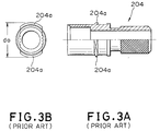
- Fig. 3A is a partly cutaway schematic front view showing the stopring 204
- Fig. 3B is its left side view.
- the stopring 204 has protrusions 204a projecting in the radial direction at two positions opposing each other on the outer peripheral surface.
- Fig. 4A is a schematic longitudinal sectional view of a plug frame 208
- Fig. 4B is its cross sectional view taken along line A-A
- Fig. 4C is a schematic front view of Fig. 4A
- Fig. 4D is a schematic left side view of Fig. 4C
- Fig. 4E is a schematic right side view of Fig. 4C.
- two positions opposing each other on the inner peripheral surface of the plug frame 208 are provided with holes 208a where projections 204a of the stopring 204 are inserted.
- An inner diameter D0 between the holes 208a is set smaller than an outer diameter d0 (see Fig. 3) between the projections 204a of the stopring 204.
- the plug frame 208 has a cutout 208b from an opening end over the axial direction at a position of 90 degrees from the holes 208a in the peripheral direction to allow elastic deformation of the plug frame 208 to open the opening.
- the stopring 204 With the opening of the plug frame 208 opened, the stopring 204 is inserted into the plug frame 208 and, with its projection 204a inserted in the hole 208a, an external force is removed to return the plug frame 208 to the original position by its elasticity so that the stopring 204 is retained through the projection 204a to the plug frame 208, as shown in Figs. 5A and 5B.
- the optical fiber cord 201 inserted into the stopring 204 and the coil spring 203 along with the boot 205, the ring 206, and the crimp ring 207 is pretreated to remove the sheath, jacket and the primary coating such that the optical fiber 201a, the optical fiber strand 201b, and the tension member 201c are exposed.
- the ferrule 202 which is separately supplied is bonded to the tip of the optical fiber cord 201. In this condition, the individual inserted parts are held with the insertion positions undetermined relative to the optical fiber cord 201.
- a core adjusting step is performed for the ferrule polished to a convex-curved surface.
- the ferrule 202 is positioned (a first rotational position) so that the flange cutout 202a of the ferrule 202 and the inner projection 208c (see Fig. 4E) of the plug frame 208 are in line. Then, the coil spring 203 and the stopring 204 are released to assemble the parts.
- Fig. 7 shows relative positions in a virtual assembly condition during the assembly work of the optical fiber cord 101, the stopring 104, the spring 103, and the ferrule 102. The assembly work at this time is all performed manually.
- the crimp ring 207 is crimped with the tension member 201c of the optical fiber cord 201 inserted between the stopring 204 and the crimp ring 207 to retain the cord.
- the boot 205 is set in position.
- the ring 206 is used to retain an excess of the sheath to the end of the crimp ring 207, an adhesive may be used in place of the ring 206.
- a coupling device and the like are assembled as shown in Fig. 2D. In such a coupling condition, the ferrule 202 is pressed to the left direction in Fig. 2 by a spring force of the coil spring 203 of which an end contacts with the stopring 2, and floatingly supported to the stopring 204 through the coil spring 203.
- a primary object of the present invention is to provide an optical fiber connector unit which facilitates construction of an automatic assembly line and enables an easy manual assembly work.
- Another object of the present invention is to provide an optical fiber connector which facilitates construction of an automatic assembly line and enables an easy manual assembly work.
- a further object of the present invention is to provide an optical fiber connector which can eliminate the need for rotational adjustment of the stopring to simplify rotational positioning in the core adjusting step of the SC-type connector, paying attention to the fact that the first rotational positioning is essential for the core adjustment, but the second rotational positioning of the stopring is required due to the structure.
- an optical fiber connector unit comprising: a ferrule having a rear end, a front end, and a through hole for holding an optical fiber strand inserted from the rear end along a central axis of the ferrule, the ferrule including a first flange formed to have a greater diameter than other portions and having an end face facing the rear end, and a second flange provided at a rear end side of the first flange and having a second flange end face opposing the first flange end face; a stopring as a cylindrical member provided outside of a part of the ferrule, having its inner peripheral surface a first step having a first end face opposing the first flange end face of the ferrule and a second step having a second end face opposing the second flange end face of the ferrule; a coil spring having one end contacting with the first flange end face of the ferrule and an other end contacting with the first end face of the stopring, exerts a first flange formed to have a greater
- the first stopper of the locating member may comprise a cylindrical portion with a portion cut out parallel to the axial direction
- the second stopper may comprise a plurality of nibs projecting inclining towards inside in the radial direction from the cylindrical portion along a direction towards the rear end of the ferrule and capable of elastic deformation for allowing the second flange of the ferrule to pass in a direction reverse to the spring force.
- the locating member may be pressed on an inner peripheral surface of the stopring by elastic deformation of the cylindrical portion.
- the nibs of the locating member may be formed on the cylindrical portion by cutting out halfway the cylindrical portion.
- the nibs of the locating member may be formed projecting from one end of the cylindrical portion.
- the second stopper of the locating member may comprise a cylindrical portion with a portion cut out parallel to the axial direction and capable of elastic deformation for allowing the second flange of the ferrule to pass in a direction reverse to the spring force
- the first stopper may comprise a plurality of nibs projecting inclining towards outside in the radial direction from the cylindrical portion along a direction towards the front end of the ferrule.
- the locating member may be pressed on an inner peripheral surface of the stopring by elastic deformation of the nibs.
- the locating member may be pressed on an outer peripheral surface of the ferrule by elastic deformation of the cylindrical portion.
- an optical fiber connector comprising: an optical fiber connector unit; having: a ferrule having a rear end, a front end, and a through hole for holding an optical fiber strand inserted from the rear end along a central axis of the ferrule, the ferrule including a first flange formed to have a greater diameter than other portions and having an end face facing the rear end, and a second flange provided at a rear end side of the first flange and having a second flange end face opposing the first flange end face; a stopring as a cylindrical member provided outside of a part of the ferrule, having its inner peripheral surface a first step having a first end face opposing the first flange end face of the ferrule and a second step having a second end face opposing the second flange end face of the ferrule; a coil spring having one end contacting with the first flange end face of the ferrule and an other end contacting with the first end
- an optical fiber connector comprising: a ferrule having a through hole for holding an optical fiber inserted from a rear end along a central axis; an optical fiber cord having an optical fiber mounted to the ferrule; a stopring as a cylindrical member provided outside a part of the ferrule in a floating condition through a coil spring, and having a flange-formed projection on an outer peripheral surface thereof; and a plug frame having an opening engaging with the outer peripheral surface of the stopring by elastic deformation in a radial direction by insertion of the stopring in an axial direction and a protrusion projecting from an inner peripheral surface of the opening to inside in a radial direction for engaging with the projection of the stopring to prevent the stopring from passing to an opening end side, and having a relation of D2 ⁇ d1 > D1 where D1 being a diameter of a circle including the inner peripheral surface of the protrusion, D2 being a diameter of a circle including the inner peripheral surface other
- the opening of the plug frame may be formed to be capable of elastic deformation by a pair of cutouts, and the protrusion may be separated by the cutouts.
- the projection of the stopring may be formed over the entire peripheral direction.
- the projection of the stopring may be separated into a plurality of pieces by cutouts disposed over a peripheral direction, and an inside end face of the protrusion of the plug frame may have at least one stopper projecting inside in an axial direction, having a width in its peripheral direction of smaller than the width of the cutout of the stopring, and engaging with the cutout for limiting rotation in a peripheral direction of the stopring engaged with the plug frame.
- An outer peripheral surface of the projection of the stopring may be provided with a serration comprising a plurality of grooves formed parallel to an axial direction
- an inner peripheral surface of the plug frame may be provided with a stopper formed parallel to an axial direction on a portion of the plug frame other than the portion in the peripheral direction where the protrusion is formed and engaging with the serration for limiting rotation in a peripheral direction of the stopring engaged with the plug frame.
- the stopring may have on its outer periphery a second projection engaging with an opening end of an opening of the plug frame, and an outer peripheral surface of the second projection may be provided with a serration comprising a plurality of grooves engaging with the stopper of the stopring.
- An optical fiber connector may further comprise: a crimp ring for mounting the tension member of the optical fiber cord at a rear end of the stopring; and a boot for covering the crimp ring mounted to the rear end of the stopring.
- the ferrule may have over an axial direction a first flange formed to have a greater diameter than other portions and having a first flange end face facing a rear end, and a second flange provided at the rear end side than the first flange and having a second flange end face opposing the first flange end face;
- the stopring has a first step having on its inner peripheral surface a first end face opposing the first flange end face of the ferrule and a second step having a second end face opposing the second flange end face of the ferrule;
- the coil spring has one end contacting with the first flange end face of the ferrule and the other end contacting with the first end face of the stopring, its tip exerting a spring force along an axial direction towards outside from the stopring on the ferrule; and the stopring and the ferrule are preassembled with a locating member provided between the two components, the locating member having a first stopper contacting the second end face of the stopring and
- An optical fiber connector may further comprise a coupling device engaged with an outer periphery of the plug frame.
- the ferrule since its second flange of the ferrule contacts against a locating member, and the ferrule is regulated to move in a direction in which the spring force of the spring is applied, the ferrule can be integrated with the stopring and the spring even before assembling an optical fiber connector.
- the ferrule since the ferrule contacts with another ferrule when an optical fiber cord is connected to the plug unit, and the ferrule can be moved against the spring force of the spring in the opposite direction to the spring force direction, the ferrule is kept in a floating condition to the stopring.
- the stopring can be inserted into the plug frame independent of its positional condition and, after the insertion, its projection contacts against the protrusion of the plug frame to prevent disconnection.
- the stopper of the plug frame engages with the cutout of the projection or a stopping groove of the stopring to prevent rotation in the peripheral direction.
- Fig. 8 is a schematic longitudinal sectional view showing a unit for the optical fiber connector according to a first embodiment of the present invention.
- This units comprises a ferrule 12, a spring 13, a stopring 14 and a locating member 15.
- the ferrule 12 made of ceramics has a rear end, a front end, and a through hole for holding an optical fiber strand (not shown) of an optical fiber cord 1 (Figs. 6A to 6C) inserted from the rear end along a central axis of the ferrule, provided at two positions in the axial direction with first and second flanges 12a and 12b formed to have greater diameters than other portions.
- the stopring 14 made of metal such as bronze is a cylindrical member having a step 14a on its inner peripheral surface, a tension member of the optical fiber cord 1 is connected to it in a connected condition.
- the spring 13 has one end contacting with an end face of the first flange 12a of the ferrule 12, and the other end contacting with an end face of the step 14a of the stopring 14 for exerting a spring force towards the outside (to the left in the figure) of the stopring 14 along the axial direction of the ferrule 12.
- the locating member 15 which will be described later in detail, is mounted on the inner peripheral surface of the stopring 14, and is adapted so that its tip contacts with an end face of the second flange 12b of the ferrule 12 for limiting movement of the ferrule 12 in a direction in which the spring force of the spring 13 is applied (to the left in the figure), and allowing movement of the ferrule 12 in the reverse direction (to the right in the figure).
- a portion adjacent to the second flange 12b of the ferrule 12 is a small diameter portion 12c which has an even smaller diameter than the inner diameter at the tip of the locating member 15. Furthermore, the second flange 12b has a tapered surface gradually decreasing in diameter towards a direction (right in the figure) reverse to the direction in which the spring force of the spring 13 is applied.
- Fig. 9 is a schematic perspective view showing the locating member 15 of the present embodiment.
- the locating member 15 formed of an elastic member such as phosphor bronze has a cylindrical portion 15a in which a portion of the cylinder is cut out parallel to the axial direction, and a plurality (four in the figure) of nibs 15b which project inclining in a direction (right direction in the figure) reverse to the direction in which the spring force of the spring 13 is applied towards the center of the stopring 14, so that allowing the second flange 12b to pass, but limiting passing of the flange 22b once passed.
- the locating member 15 is mounted on the inner peripheral surface of the stopring 14 by its elasticity due to elastic deformation of the cylindrical portion 15a, and a tip of the nibs 15b contacts with the end face of the second flange 12b of the ferrule 12.
- both end faces of the spring 13 are compressively deformed by the stopring 14 and the ferrule 12 to generate a pressure.
- a pressure due to a repulsive force of the spring 13 is applied as pressurization to the tip of the locating member 15, relative positions of the individual parts are exactly determined by the pressurization.
- the parts assembled as in Fig. 8 are hereinafter referred to as an optical fiber connector unit.
- the second flange 12b as a rear end of the ferrule 12 is separated from the locating member 15 as shown in Fig. 10 so that the inner peripheral surface of the locating member 15 opposes the small diameter portion 12c, making both members non-contacting. Therefore, the ferrule 12 is released from binding of the locating member 15, achieving a floating condition which is the feature of the SC-type connector. Under this condition, even when the stopring 14 is dislocated by an external force, no external force is transmitted to the ferrule 12 through the locating member 15, and the stopring 14 and the ferrule 12 contact with each other only through the spring 13, thereby maintaining a flexible condition.
- Fig. 11 is a schematic cross sectional view showing a second embodiment of the optical fiber connector unit.
- the second embodiment differs from the first embodiment in that the portion adjacent to a second flange 22b of a ferrule 22 differs in shape. That is, the ferrule does not include the small diameter portion 12c in the first embodiment.
- Fig. 12 is a schematic view showing relative positions of the stopring 14 and the second flange 22b of the ferrule 22 after normal assembly of the second embodiment.
- the ferrule 22 is always in contact with the locating member 15.
- the stopring 14 and the ferrule 22 do not become non-contacting, not making a flowing structure in the strict sense.
- the nibs 15b of the locating member are formed to a small thickness, it is possible to set the spring constant of the nibs 15b to a sufficiently small value compared to that of the spring 13.
- the binding force which the locating member 15 exerts on the ferrule 22 when the stopring 14 is dislocated can be made sufficiently small compared to the binding force of the spring 13 to the ferrule 22, achieving a substantial floating mechanism.
- the second embodiment where the locating member 15 is always in contact with the stopring 14 and the ferrule 22 is a structure which can reduce the man-power in the ferrule machining compared to the first embodiment, and a reduction in parts cost is possible. Further, since, in the optical fiber connector unit of the present embodiment, the locating member 15 contacts to press the outer peripheral surface of the ferrule 22 in the radial direction, the ferrule 22 is held at the center of the stopring 14. Therefore, it is easy to achieve automation of subsequent assembly work.
- the above two embodiments use the locating member 15, but it is not limited to this. Any structure may be used in which the locating member contacts with the second flange 12b (or 22b) of the ferrule 12 (or 22) to limit movement in the axial direction of the ferrules 12 and 22 due to the spring force of the spring 13, but allow movement in the direction reverse to the spring force direction.
- the locating member is not limited to one which is shown in Fig. 9, but may be, for example, one which is shown in Fig. 13A or 14A.
- Fig. 13A is a schematic perspective view showing a locating member in another embodiment of the present invention
- Fig. 13B is a schematic cross sectional view showing the incorporated locating member of Fig. 13A.
- a locating member 16 comprises a cylindrical portion 16a which is formed by cutting out a portion of a cylinder parallel to the axial direction so that it elastically deforms to allow the second flange 12b of the ferrule 12 to pass, and a plurality (four in the figure) of nibs 16b integrally projecting from the cylindrical portion 16a towards the inner peripheral surface of the stopring 12.
- Fig. 13A a locating member 16 comprises a cylindrical portion 16a which is formed by cutting out a portion of a cylinder parallel to the axial direction so that it elastically deforms to allow the second flange 12b of the ferrule 12 to pass, and a plurality (four in the figure) of nibs 16b integrally projecting from the cylindrical portion 16a towards the inner peripheral surface of the stopring 12.
- the locating member 16 is mounted on the outer peripheral surface of the ferrule 22 by its elasticity due to elastic deformation of the nibs 16b so that the cylindrical portion 16a contacts against the end face of the second flange 22b of the ferrule 22.
- the outer diameter of the tip of the nibs 16b is nearly the same as the inner diameter of the stopring 14 to position the ferrule 22 at nearly the center of the stopring 14, while maintaining the substantial floating mechanism.
- the locating member 16 can also be used for the above-described ferrule 12 as well.
- FIG. 14A is a schematic perspective view showing a locating member in another embodiment of the present invention
- Fig. 14B is a schematic cross sectional view showing the incorporated locating member of Fig. 14A.
- a locating member 17 shown in Fig. 14A comprises a cylindrical portion 17a which is formed by cutting out a portion of a cylinder parallel to the axial direction, and a plurality (three in the figure) of nibs 17b provided at an end of the cylindrical portion 17a and projecting inward in the radial direction to the right in the figure.
- the nibs 17b allow the flange 22b of the ferrule 22 to pass, but limits passing of the flange 22b once passed in the reverse direction.
- the inner diameter of the tips of the nibs 17b are nearly the same as the diameter of the outer peripheral surface of the ferrule 22 to position the ferrule 22 at nearly the center of the stopring 14, while maintaining he substantial floating mechanism.
- the locating member 17 can also be used for the above-described ferrule 12 as well.
- Fig. 15 is a schematic cross sectional view showing an optical fiber connector incorporating the optical fiber connector unit according to the second embodiment
- Figs. 16A to 16C are schematic cross sectional view showing the assembly process of the optical fiber connector of Fig. 15. Assembly process of the optical fiber connector will be described with reference to Figs. 16A to 16C.
- a tip of the optical fiber cord 1 previously inserting to a boot 5, and a crimp ring 7 is pretreated by sheath removing, jacket removing, primary coat removing, and the like to expose an optical fiber 1a, an optical fiber strand 1b, and a tension member 1c. Then, the optical fiber cord 1 is bonded to the ferrule 22 of the optical fiber connector.
- a plug frame 8 is mounted to the ferrule 22.
- a projection 24a of a stopring 24 is engaged with a hole 208a of the plug frame 208, and both components are retained in a floating condition.
- the locating member is mounted by elasticity on the inner peripheral surface of the stopring and abutted with the flange of the ferrule.
- an alternative construction may be used in which the locating member is mounted by elasticity on the outer peripheral surface of the ferrule and abutted to the flange on the inner peripheral surface of the stopring.
- the locating member 16 of Fig. 13A is mounted to the ferrule 22 by elastic deformation of the cylindrical portion 16a, and the tips of the nibs 16b are abutted with the flange 14b of the stopring 14 to construct a stable optical fiber connector. In this case, if the diameter of the tips of the nibs 16b and the inner diameter of the stopring 14 are nearly the same, positioning and floating mechanism of the ferrule can be assured.
- the storing, the spring, and the ferrule are constructed to an integral structure using the locating member, parts can be easily controlled without losing the connection compatibility with conventional SC-type connectors.
- an automatic assembly line of optical fiber connector can be easily constructed, thereby achieving a reliable optical fiber connector of stable quality at a reduced cost.
- the assembly work can be simplified when the present embodiment is applied in manual assembly, particularly in the field assembly with poor work environment.
- optical fiber connector which can simplify the core adjusting step to assemble the plug frame of the optical fiber connector will be described below.
- Fig. 17A is a partly cutaway schematic front view showing a stopring according to a third embodiment of the present invention
- Fig. 17B is its left side view
- Fig. 17C is a schematic longitudinal sectional view showing a plug frame according to the third embodiment of the present invention
- Fig. 17D is its schematic cross sectional view taken along line C-C.
- the stopring 14 as in the prior art, is a cylindrical member for supporting the ferrule in a floating condition through a coil spring, and has a flange-formed protrusion 14a over the entire circumference of the outer peripheral surface.
- the plug frame 18 made of plastics such as polybutylene terephthalate (PBT), as in the prior art, has a pair of cutouts 18b extending in the axial direction to be able to open the opening by elastic deformation in the radial direction, and is provided with a pair of protrusions 18c projecting in the radial direction for contacting with the projection 14a of the inserted stopring 14 to prevent passing through to the opening end side.
- the protrusions 18c are provided adjacent at the opening end side to the hole 18a formed as the hole 208a in the prior art.
- D1 is a diameter of a circle including the inner peripheral surfaces of the protrusions 18c
- D2 is a diameter of a circle including the inner peripheral surface other than the protrusions 18c
- d1 is an outer diameter of the projection 14a of the stopring 14. That is, in a connected condition, the outer shape of the projection 14a is as indicated by the phantom line (chain double-dashed line) L2 in Fig. 17 (d).
- the projection 14a of the stopring 14 is provided over the entire circumference of the outer peripheral surface, and the diameters D1 and D2 in the plug frame 18 and the outer diameter d1 of the projection 14a have a relation of D2 ⁇ d1 > D1.
- Insertion of the stopring 14 into the plug frame 18 in the third embodiment can be carried out independent of the position of the stopring 14 in the peripheral direction.
- the optical fiber connector using the stopring 14 and the plug frame 18 can simplify the assembly process without losing the connection compatibility of the prior art SC-type connector, enabling easy automatic assembly.
- Other parts of the optical fiber connector are essentially similar to those in the prior art, and description thereof is omitted.
- the ferrule, the spring, and the stopring may be made to the optical fiber connector using the locating member of the above-described embodiments.
- stopring and plug frame which can limit rotation in the peripheral direction of the stopring after engagement.
- Fig. 18A is a partly cutaway schematic front view of the stopring according to a fourth embodiment of the present invention
- Fig. 18B is its schematic left side view
- Fig. 18C is a schematic longitudinal sectional view showing the plug frame according to the fourth embodiment of the present invention
- Fig. 18D is its schematic cross sectional view taken along line D-D
- Fig. 18E is its schematic plan view.
- Fig. 19 is a schematic perspective view showing the plug frame 28
- Figs. 20A and 20B are schematic views showing engaging condition of the plug frame 28 with the stopring 24.
- a projection 24a of the stopring 24 has a plurality (four in this embodiment) of cutouts 24c over the peripheral direction. Furthermore, as shown in Figs. 18C, 18D, and 18E, holes 28a and protrusions 28c of the plug frame 28 are provided with stoppers 28d which engage with the cutouts 24c of the projection 24a contacting with the protrusion 28c and project in the axial direction to limit rotation in the peripheral direction of the plug frame 28. In this case, the widths of the protrusions 28c is formed greater than the widths of the cutouts 24c. Other structures of the present embodiment are similar to the third embodiment.
- the fourth embodiment in addition to the third embodiment, has an effect that the stoppers 28d engages with the cutouts 24c to limit rotation in the peripheral direction of the stopring 24.
- Insertion of the stopring 24 into the plug frame 28 in the fourth embodiment can be carried out independent of the position of the stopring 24 in the peripheral direction.
- the protrusions 28c and the projection 24a may be in a contact condition with the cutouts 24c not engaged with the stoppers 28d.
- rotation of the stopring 24 is limited at a position where the cutouts 24c engages with the stoppers 28d. In this case, since the stopring 24 supports the ferrule in a floating condition, the ferrule will never move.
- the optical fiber connector using the stopring 24 and the plug frame 28 is easy for automatic assembly.
- Other parts of the optical fiber connector are essentially the same as in the prior art, and description thereof is omitted.
- the ferrule, the spring, and the stopring may be made to the optical fiber connector unit using the locating member of the above-described embodiments.
- the optical fiber connector is constructed using the ferrule 22, the spring 13, and the locating member 15 (not shown) of the above embodiment.
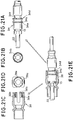
- FIG. 21A is a schematic front view showing a optical fiber connector using a stopring 34
- Fig. 21B is its schematic left side view
- Fig. 21C is a schematic longitudinal sectional view showing a plug frame 38
- Fig. 21D is its schematic right side view
- Fig. 21E is a partly cutaway schematic cross sectional view showing engaging condition of these components.
- outer peripheral surfaces of a projection 34a and a second projection 34d of a stopring 34 are provided with serrations 34e and 34f comprising parallel grooves along the insertion direction for stopping rotation.
- inner peripheral surface of the plug frame 38 is provided with rotation stoppers 38e engaging with the serration 34e and 34f extending to the opening end at portions other than protrusions 38c of the above third embodiment.
- the maximum diameter of the serrations 34e is the above-described d1
- a diameter of inner peripheral surface of the stoppers 38e is the above-described D1
- the relation of these diameters with D2 is the same as in the above third embodiment.
- Other construction of the present embodiment is similar to the third embodiment.
- the stopring 34 is integrated with the ferrule 22, the spring 13, and a locating member (not shown) to form an optical fiber connector.
- the fifth embodiment in addition to the third embodiment, has an effect that the serrations 34e and 34f engage with the stoppers 38e to limit rotation in the peripheral direction of the stopring 34.
- Insertion of the stopring 34 into the plug frame 38 in the fifth embodiment can be carried out independent of the position of the stopring 24 in the peripheral direction. In this case, since the stopring 34 supports the ferrule in a floating condition, the ferrule will never move.
- the optical fiber connector of the construction of the third to fifth embodiments of the present invention can eliminate the need for the second positioning of the stopring and the plug frame in the assembly, the assembly work is considerably simplified. As a result, construction of the automatic assembly line of the optical fiber connector is simplified, thereby achieving stable quality, reliability, and cost reduction of the optical fiber connector. Furthermore, in addition to the above effects, the assembly work can be simplified for manual assembly, particularly in the field assembly of the optical fiber connector which is very poor in the assembly environment. Furthermore, in the optical fiber connector of the fourth and fifth embodiments, rotation of the stopring after connection is prevented.
Landscapes
- Physics & Mathematics (AREA)
- General Physics & Mathematics (AREA)
- Optics & Photonics (AREA)
- Mechanical Coupling Of Light Guides (AREA)
Applications Claiming Priority (6)
| Application Number | Priority Date | Filing Date | Title |
|---|---|---|---|
| JP112552/93 | 1993-05-14 | ||
| JP11255293 | 1993-05-14 | ||
| JP11255293A JPH06324231A (ja) | 1993-05-14 | 1993-05-14 | 光ファイバコネクタ機構 |
| JP11833393A JP3166805B2 (ja) | 1993-05-20 | 1993-05-20 | 光ファイバコネクタ |
| JP118333/93 | 1993-05-20 | ||
| JP11833393 | 1993-05-20 |
Publications (3)
| Publication Number | Publication Date |
|---|---|
| EP0624810A2 true EP0624810A2 (de) | 1994-11-17 |
| EP0624810A3 EP0624810A3 (de) | 1996-07-31 |
| EP0624810B1 EP0624810B1 (de) | 2001-08-01 |
Family
ID=26451686
Family Applications (1)
| Application Number | Title | Priority Date | Filing Date |
|---|---|---|---|
| EP94107485A Expired - Lifetime EP0624810B1 (de) | 1993-05-14 | 1994-05-13 | Baugruppe für Glasfaserverbindung und Glasfaserstecker |
Country Status (3)
| Country | Link |
|---|---|
| US (1) | US5436995A (de) |
| EP (1) | EP0624810B1 (de) |
| DE (1) | DE69427841T2 (de) |
Cited By (7)
| Publication number | Priority date | Publication date | Assignee | Title |
|---|---|---|---|---|
| US5524159A (en) * | 1994-11-04 | 1996-06-04 | The Whitaker Corporation | Fiber optic connector |
| US5577144A (en) * | 1995-05-30 | 1996-11-19 | The Whitaker Corporation | Fiber optic connector |
| US5625731A (en) * | 1994-12-06 | 1997-04-29 | The Whitaker Corporation | Process for assembling an optical fiber connector |
| EP0710860B1 (de) * | 1994-11-04 | 2002-10-09 | The Whitaker Corporation | Fiberoptischer Stecker |
| EP1237023A3 (de) * | 2001-03-02 | 2002-11-13 | Hirose Electric Co., Ltd. | Steckerstifthaltestruktur für eine optische Steckerkomponente |
| EP1324085A1 (de) * | 2001-12-12 | 2003-07-02 | Itt Manufacturing Enterprises, Inc. | Herausnehmbarer Lichtwellenleiterstecker |
| EP1335222A1 (de) * | 2002-02-08 | 2003-08-13 | Diamond SA | Steckerteil für eine optische Steckverbindung |
Families Citing this family (34)
| Publication number | Priority date | Publication date | Assignee | Title |
|---|---|---|---|---|
| EP0766838B1 (de) * | 1994-06-22 | 2002-03-06 | The Whitaker Corporation | Faseroptischer stecker mit verbesserten mitteln zum zusammenbau |
| US5717802A (en) * | 1994-09-19 | 1998-02-10 | The Whitaker Corporation | Fiber optic connectors having spring-loaded ferrules |
| US6139195A (en) * | 1996-05-22 | 2000-10-31 | Minnesota Mining And Manufacturing Company | Strain relief for a coated optical fiber in a connector |
| US5828806A (en) * | 1996-10-10 | 1998-10-27 | Molex Incorporated | Fiber optic connector |
| JP3566045B2 (ja) * | 1997-10-02 | 2004-09-15 | アルプス電気株式会社 | 記録媒体の装着装置 |
| JP2000241662A (ja) * | 1999-02-22 | 2000-09-08 | Seiko Instruments Inc | 光コネクタ及び光コネクタの製造方法 |
| US6296399B1 (en) * | 1999-07-02 | 2001-10-02 | Delphi Technologies, Inc. | Fiber optic connection system |
| US6238101B1 (en) | 1999-07-08 | 2001-05-29 | Molex Incorporated | Tunable fiber optic connector |
| WO2001088584A1 (fr) | 2000-05-12 | 2001-11-22 | Takeo Inagaki | Connecteur de fibres optiques |
| US6428215B1 (en) | 2000-12-27 | 2002-08-06 | Adc Telecommunications, Inc. | Tunable fiber optic connector and method for assembling |
| US6582133B2 (en) | 2001-05-30 | 2003-06-24 | Tropic Networks Inc. | Module and method for interconnecting optoelectronic cards |
| US6629782B2 (en) | 2002-02-04 | 2003-10-07 | Adc Telecommunications, Inc. | Tuned fiber optic connector and method |
| US6913396B2 (en) * | 2002-11-01 | 2005-07-05 | Adc Telecommunications, Inc. | Tunable fiber optic connector and device and method for tuning a connector |
| US6918704B2 (en) * | 2003-01-30 | 2005-07-19 | Panduit Corp. | Tunable fiber optic connector |
| USD528505S1 (en) | 2003-12-03 | 2006-09-19 | Panduit Corp. | Fiber optic connector |
| CH697521B1 (de) * | 2005-01-19 | 2008-11-28 | Diamond Sa | Steckerteil für eine optische Steckverbindung. |
| JP4523874B2 (ja) * | 2005-06-01 | 2010-08-11 | ホシデン株式会社 | 光コネクタ |
| JP5313513B2 (ja) * | 2008-02-04 | 2013-10-09 | スリーエム イノベイティブ プロパティズ カンパニー | 光ファイバコードの保持装置及び保持方法並びに光ファイバ接続装置 |
| AR071489A1 (es) * | 2008-04-21 | 2010-06-23 | Adc Telecommunications Inc | Conector de fibra optica endurecido con cuerpo conector unido a un cable cilindrico por una envoltura unitaria |
| JP5281959B2 (ja) * | 2008-06-12 | 2013-09-04 | 株式会社精工技研 | 光コネクタ用ストップリング及びそれを用いた光コネクタ付き光ファイバコード並びに光コネクタ付き光ファイバコードの製造方法。 |
| JP4863319B2 (ja) * | 2009-05-19 | 2012-01-25 | 日本航空電子工業株式会社 | 光コネクタ |
| JP2011185975A (ja) * | 2010-03-04 | 2011-09-22 | Seikoh Giken Co Ltd | 光コネクタキット |
| US8503848B2 (en) * | 2011-01-27 | 2013-08-06 | Hewlett-Packard Development Company, L.P. | Waveguide arrays |
| CN102385120A (zh) * | 2011-10-27 | 2012-03-21 | 中航光电科技股份有限公司 | 预连接光纤连接器 |
| CN102385118A (zh) * | 2011-10-27 | 2012-03-21 | 中航光电科技股份有限公司 | 光纤连接器及其适配器 |
| CN102385117A (zh) * | 2011-10-27 | 2012-03-21 | 中航光电科技股份有限公司 | 光纤连接器插针组件 |
| CN104364686B (zh) | 2012-02-07 | 2016-11-16 | 泰科电子瑞侃有限公司 | 用于连接器的线缆端接组件和方法 |
| US9081154B2 (en) | 2012-09-12 | 2015-07-14 | Tyco Electronics Raychem Bvba | Method of tuning a fiber optic connector |
| US9235010B2 (en) | 2013-06-28 | 2016-01-12 | Commscope Technologies Llc | Robust optical crimp connector |
| JP5656099B1 (ja) * | 2013-06-28 | 2015-01-21 | Toto株式会社 | 光レセプタクル、フェルールおよびプラグフェルール |
| CN109073838B (zh) | 2016-03-10 | 2021-03-30 | 康宁光电通信有限责任公司 | 具有套圈缩回平衡的基于套圈的光纤连接器 |
| US10386583B2 (en) * | 2017-06-09 | 2019-08-20 | Seikoh Giken Co., Ltd. | Optical connector |
| CN110609360A (zh) * | 2018-09-30 | 2019-12-24 | 中航光电科技股份有限公司 | 一种光纤连接器及其光纤接触件 |
| CN112230355B (zh) * | 2020-09-27 | 2021-12-14 | 华为技术有限公司 | 一种光学连接器 |
Family Cites Families (20)
| Publication number | Priority date | Publication date | Assignee | Title |
|---|---|---|---|---|
| US4240695A (en) * | 1979-06-20 | 1980-12-23 | E. I. Du Pont De Nemours And Company | Optical fibers connector |
| US4461537A (en) * | 1981-12-24 | 1984-07-24 | Molex Incorporated | Fiber optic connector assembly |
| JPH0646249B2 (ja) * | 1985-03-08 | 1994-06-15 | 株式会社日立製作所 | 光フアイバコネクタ |
| US4712860A (en) * | 1985-07-15 | 1987-12-15 | Itt Corporation | Retrofittable optic fiber contact assembly |
| US4735480A (en) * | 1985-11-20 | 1988-04-05 | Raychem Corp. | Optical fiber connector |
| JPH0778568B2 (ja) * | 1987-02-09 | 1995-08-23 | 日本電信電話株式会社 | 光コネクタプラグ |
| JPH01502859A (ja) * | 1987-03-24 | 1989-09-28 | レイケム・コーポレイション | ピン・アンド・ソケット光ファイバーコネクター |
| JPH0812307B2 (ja) * | 1987-05-22 | 1996-02-07 | 富士通株式会社 | 光コネクタ |
| US4804243A (en) * | 1987-09-04 | 1989-02-14 | Itt Corporation | Contact retention arrangement |
| JPH02251917A (ja) * | 1989-03-27 | 1990-10-09 | Jiyaruko:Kk | 光ファイバー用プラグ |
| US5016970A (en) * | 1989-08-22 | 1991-05-21 | Nippon Telegraph And Telephone Corp. | Ferrule for optical fiber transmitting linearly polarized light and optical fiber connector using this ferrule |
| US4944568A (en) * | 1989-09-05 | 1990-07-31 | Molex Incorporated | Fiber optic connector assembly |
| JPH0424708U (de) * | 1990-06-19 | 1992-02-27 | ||
| JPH0497107A (ja) * | 1990-08-09 | 1992-03-30 | Furukawa Electric Co Ltd:The | 光コネクタ |
| US5129023A (en) * | 1991-05-14 | 1992-07-07 | At&T Bell Laboratories | Optical fiber connector having enhanced provisions for interconnection and for prevention of optical and mechanical disconnection |
| US5261019A (en) * | 1992-01-02 | 1993-11-09 | Adc Telecommunications, Inc. | Fiber optic connector |
| US5212752A (en) * | 1992-05-27 | 1993-05-18 | At&T Bell Laboratories | Optical fiber ferrule connector having enhanced provisions for tuning |
| US5265183A (en) * | 1992-07-02 | 1993-11-23 | Molex Incorporated | Fiber optic connector and tool for assembling same |
| US5311609A (en) * | 1992-10-29 | 1994-05-10 | Hirose Electric Co., Ltd. | Optical fiber connector |
| US5287425A (en) * | 1993-02-26 | 1994-02-15 | Foxconn International, Inc. | Optical fiber SC type connector assembly with partly pre-assembled components |
-
1994
- 1994-05-11 US US08/240,622 patent/US5436995A/en not_active Expired - Fee Related
- 1994-05-13 DE DE69427841T patent/DE69427841T2/de not_active Expired - Fee Related
- 1994-05-13 EP EP94107485A patent/EP0624810B1/de not_active Expired - Lifetime
Cited By (11)
| Publication number | Priority date | Publication date | Assignee | Title |
|---|---|---|---|---|
| US5524159A (en) * | 1994-11-04 | 1996-06-04 | The Whitaker Corporation | Fiber optic connector |
| EP0710860B1 (de) * | 1994-11-04 | 2002-10-09 | The Whitaker Corporation | Fiberoptischer Stecker |
| US5625731A (en) * | 1994-12-06 | 1997-04-29 | The Whitaker Corporation | Process for assembling an optical fiber connector |
| US5724723A (en) * | 1994-12-06 | 1998-03-10 | The Whitaker Corporation | Apparatus for assembling an optical fiber connector |
| US5577144A (en) * | 1995-05-30 | 1996-11-19 | The Whitaker Corporation | Fiber optic connector |
| EP1237023A3 (de) * | 2001-03-02 | 2002-11-13 | Hirose Electric Co., Ltd. | Steckerstifthaltestruktur für eine optische Steckerkomponente |
| US6599027B2 (en) | 2001-03-02 | 2003-07-29 | Hirose Electric Co., Ltd. | Ferrule holding structure for optical connector component |
| EP1324085A1 (de) * | 2001-12-12 | 2003-07-02 | Itt Manufacturing Enterprises, Inc. | Herausnehmbarer Lichtwellenleiterstecker |
| US6722789B1 (en) | 2001-12-12 | 2004-04-20 | Itt Manufacturing Enterprises, Inc. | Releasable terminus retention |
| EP1335222A1 (de) * | 2002-02-08 | 2003-08-13 | Diamond SA | Steckerteil für eine optische Steckverbindung |
| WO2003067298A1 (de) * | 2002-02-08 | 2003-08-14 | Diamond Sa | Steckerteil für eine optische steckverbindung |
Also Published As
| Publication number | Publication date |
|---|---|
| DE69427841T2 (de) | 2002-04-04 |
| US5436995A (en) | 1995-07-25 |
| DE69427841D1 (de) | 2001-09-06 |
| EP0624810A3 (de) | 1996-07-31 |
| EP0624810B1 (de) | 2001-08-01 |
Similar Documents
| Publication | Publication Date | Title |
|---|---|---|
| US5436995A (en) | Optical fiber connector unit and optical fiber connector | |
| CA1321911C (en) | Fiber optic connector element and method for its use | |
| US8702324B2 (en) | Reversible fiber optic stub clamping mechanism | |
| US7270487B2 (en) | Field installable optical fiber connector | |
| US6379054B2 (en) | Field installable multifiber connector | |
| US4877303A (en) | Fiber optic connector element & method for its use | |
| US5993070A (en) | Optical connector and a method of attaching the same | |
| US4738508A (en) | Terminated optical fiber and methods of making | |
| RU2133050C1 (ru) | Способ полирования волоконно-оптических наконечников | |
| EP2270561B1 (de) | Glasfaserstecker mit Faserabschnitt und Linse zur Strahlaufweitung und Verfahren der Herstellung | |
| EP0421305B1 (de) | Faseroptische Spleisseinheit | |
| WO2020145010A1 (ja) | 光コネクタの製造方法 | |
| JP2842765B2 (ja) | 光コネクタフェルールの回転止め構造 | |
| US6846111B2 (en) | Method of processing optical fiber end portion | |
| JP5160706B2 (ja) | 光ファイバーケーブルの端末装置 | |
| US12078850B2 (en) | Fiber optic connectors with funnel-shaped boots and methods of installing the same | |
| JP3215098B2 (ja) | 光減衰ファイバ組立体および光減衰器 | |
| JP3166805B2 (ja) | 光ファイバコネクタ | |
| JP2004309749A (ja) | 現場組立光コネクタ及びその組立方法 | |
| JPH04247414A (ja) | 光コネクタ | |
| JPH11142686A (ja) | フェルール及び光コネクタ | |
| JPS5934887Y2 (ja) | 光ファイバコネクタ | |
| JPS63118108A (ja) | 光コネクタフェル−ル | |
| JPH07318757A (ja) | 光コネクタおよびその接続方法 |
Legal Events
| Date | Code | Title | Description |
|---|---|---|---|
| PUAI | Public reference made under article 153(3) epc to a published international application that has entered the european phase |
Free format text: ORIGINAL CODE: 0009012 |
|
| AK | Designated contracting states |
Kind code of ref document: A2 Designated state(s): DE GB IT SE |
|
| RAP1 | Party data changed (applicant data changed or rights of an application transferred) |
Owner name: NIPPON TELEGRAPH AND TELEPHONE CORPORATION |
|
| PUAL | Search report despatched |
Free format text: ORIGINAL CODE: 0009013 |
|
| AK | Designated contracting states |
Kind code of ref document: A3 Designated state(s): DE GB IT SE |
|
| 17P | Request for examination filed |
Effective date: 19960917 |
|
| 17Q | First examination report despatched |
Effective date: 19990203 |
|
| GRAG | Despatch of communication of intention to grant |
Free format text: ORIGINAL CODE: EPIDOS AGRA |
|
| GRAG | Despatch of communication of intention to grant |
Free format text: ORIGINAL CODE: EPIDOS AGRA |
|
| GRAH | Despatch of communication of intention to grant a patent |
Free format text: ORIGINAL CODE: EPIDOS IGRA |
|
| GRAH | Despatch of communication of intention to grant a patent |
Free format text: ORIGINAL CODE: EPIDOS IGRA |
|
| GRAA | (expected) grant |
Free format text: ORIGINAL CODE: 0009210 |
|
| AK | Designated contracting states |
Kind code of ref document: B1 Designated state(s): DE GB IT SE |
|
| REF | Corresponds to: |
Ref document number: 69427841 Country of ref document: DE Date of ref document: 20010906 |
|
| REG | Reference to a national code |
Ref country code: GB Ref legal event code: IF02 |
|
| PLBE | No opposition filed within time limit |
Free format text: ORIGINAL CODE: 0009261 |
|
| STAA | Information on the status of an ep patent application or granted ep patent |
Free format text: STATUS: NO OPPOSITION FILED WITHIN TIME LIMIT |
|
| 26N | No opposition filed | ||
| PGFP | Annual fee paid to national office [announced via postgrant information from national office to epo] |
Ref country code: GB Payment date: 20040426 Year of fee payment: 11 |
|
| PGFP | Annual fee paid to national office [announced via postgrant information from national office to epo] |
Ref country code: SE Payment date: 20040527 Year of fee payment: 11 |
|
| PGFP | Annual fee paid to national office [announced via postgrant information from national office to epo] |
Ref country code: DE Payment date: 20040601 Year of fee payment: 11 |
|
| PG25 | Lapsed in a contracting state [announced via postgrant information from national office to epo] |
Ref country code: IT Free format text: LAPSE BECAUSE OF NON-PAYMENT OF DUE FEES Effective date: 20050513 Ref country code: GB Free format text: LAPSE BECAUSE OF NON-PAYMENT OF DUE FEES Effective date: 20050513 |
|
| PG25 | Lapsed in a contracting state [announced via postgrant information from national office to epo] |
Ref country code: SE Free format text: LAPSE BECAUSE OF NON-PAYMENT OF DUE FEES Effective date: 20050514 |
|
| PG25 | Lapsed in a contracting state [announced via postgrant information from national office to epo] |
Ref country code: DE Free format text: LAPSE BECAUSE OF NON-PAYMENT OF DUE FEES Effective date: 20051201 |
|
| EUG | Se: european patent has lapsed | ||
| GBPC | Gb: european patent ceased through non-payment of renewal fee |
Effective date: 20050513 |