EP0624840A1 - Système de calculateur déductif - Google Patents
Système de calculateur déductif Download PDFInfo
- Publication number
- EP0624840A1 EP0624840A1 EP94110208A EP94110208A EP0624840A1 EP 0624840 A1 EP0624840 A1 EP 0624840A1 EP 94110208 A EP94110208 A EP 94110208A EP 94110208 A EP94110208 A EP 94110208A EP 0624840 A1 EP0624840 A1 EP 0624840A1
- Authority
- EP
- European Patent Office
- Prior art keywords
- fuzzy
- reasoning
- rule
- computer
- storage
- Prior art date
- Legal status (The legal status is an assumption and is not a legal conclusion. Google has not performed a legal analysis and makes no representation as to the accuracy of the status listed.)
- Withdrawn
Links
Images








Classifications
-
- G—PHYSICS
- G06—COMPUTING OR CALCULATING; COUNTING
- G06N—COMPUTING ARRANGEMENTS BASED ON SPECIFIC COMPUTATIONAL MODELS
- G06N7/00—Computing arrangements based on specific mathematical models
- G06N7/02—Computing arrangements based on specific mathematical models using fuzzy logic
- G06N7/04—Physical realisation
Definitions
- This invention relates to a reasoning computer system, and more particularly to an improved reasoning computer system having a simplified construction and versatile applications.
- a reasoning or inference computer system in a multi-stage construction including a primary reasoning computer at a rank having a reasoning means for producing a reasoned result, at least one child reasoning computers at a lower rank having a reasoning means for producing a reasoning result, and a means for providing the reasoning results by the child reasoning computers to the reasoning means of the primary reasoning computer, whereby the reasoning by the primary reasoning computer is assisted by the child reasoning computers.
- a fuzzy reasoning computer system including a means for providing a membership function with pulse widths representing membership values corresponding to fuzzy variables.
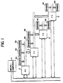
- Fig. 1 there is shown an example of a schematic construction of a system as a preferred embodiment of this invention.
- fuzzy computers (briefly "FC") 2, 3, 4 and 5 under a higher rank computer 1 including of micro-miniaturized digital computer, so called micro-computer.
- This system is constructed in a multistage fashion, with the first fuzzy computer 2 being associated with the second fuzzy computer 3, for instance.
- the FC 2 is designed to receive the reasoning or inference results from the lower rank computer FC 3 as an input thereof to be reasoned or inferred in addition to the reasoning based on output from a plurality of sensors 6a.
- a lower rank FCc executes a reasoning according to outputs from sensors 6 and 6 associated thereto to apply a reasoning result to the higher rank FCa in a signal shape equal to the signal shape produced from the sensors 6 and 6, so that the higher rank FCa cannot discriminate whether the signal applied thereto is directly given by the sensors or the reasoning result by the FCc though such discrimination is not necessary in this embodiment.
- the section 7 shown by the dotted line plays the role of a sort of sensor, or a fuzzy sensor.
- the FC 2 exemplarily shown in Fig. 3 is connected with the MPU 1 through a higher rank bus 8.
- the MPU 1 stores fuzzy production rules into a fuzzy rule storage 9 through the bus 8 beforehand.
- the MPU 1 transfers data representing the proposition to a rule controller 10 through bus 8.
- the rule controller 10 selects from storage 9 a rule to be activated, and the selected rule is set to a fuzzy rule register 11.
- the rule set in the fuzzy rule register 11 is examined as to whether a fuzzy variable should be read by an input controller 12 from an external input or from a fuzzy conclusion storage unit 13 set out later.
- the fuzzy variable selected by the examination is applied to a fuzzy reasoning unit 14 together with the rule from the register 11 to execute a reasoning.
- the result of the reasoning is applied to the fuzzy conclusion storage unit 13 and transferred to MPU 1 through a conclusion storage controller 15 and the higher rank bus 8.
- the MPU 1 can freely access the fuzzy rule storage 9, the rule controller 10 and the conclusion storage controller 15 to execute and complete a desired reasoning.
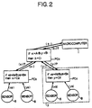
- the MPU 1 informs the FCa that it has to execute a reasoning about Z1. That is, MPU 1 makes a request for a defuzzified output thereto.
- the FCa inquires where the fuzzy variable, x1 or y1, of the above fuzzy production rule at its antecedent is gained. Though the inquiry will be described later in detail, it is processed by the conventional fuzzy computer method if the fuzzy variable is obtained from the sensors 6 as an affirmed or decided value. If the variable is obtained from a result by another FC, however, all rules having at their consequents x1 or y1 are executed in a particular FC and the synthetic reasoning result gained from results by the execution is applied to FCa from FCb or FCc as an decided value.
- the system in this embodiment is not limited by the two class construction consisting of FCa and FCb or FCc shown in Fig. 2, and has features such that if a FC located in a certain class executes a rule at its antecedent having a fuzzy variable not gained by any output from sensors, the FCs generating the above-mentioned fuzzy variable (viz., the lower rank) are sequentially activated.
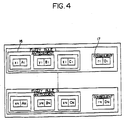
- the fuzzy rule storage 9 stores a plurality of fuzzy production rules in the "if-then" formula. As shown in Fig. 4, each rule has antecedent 16 and consequent 17.
- the fuzzy production rules (briefly called also “fuzzy rules") are written into the fuzzy rule storage 9 beforehand by MPU 1.
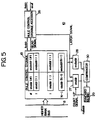
- a start address "staddr (i)” and an end address “endaddr (i)” in a rule control memory 18 show the address of the fuzzy rule storage 9 where the rule at its antecedent having the same fuzzy variable is stored.
- Fig. 6 shows the storage relationship between fuzzy rule storage 9 and rule control storage 18.
- MPU 1 writes fuzzy rules and rule control data into all FCs so that the system in this embodiment is initialized. Then, MPU 1 instructs disclosures of reasoning regarding predetermined items, while this instruction is applied to the conclusion storage controller 15 of Fig. 3 through the higher rank bus 8.
- the construction of the conclusion storage controller 15 is shown in Fig. 7.
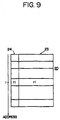
- the fuzzy conclusion storage unit 13 is also shown in Fig. 8, and its fuzzy conclusion storage 20 is shown in Fig. 9.
- the fuzzy conclusion storage 20 stores reasoning results.
- the reasoning result representing a fuzzy variable value is set to a conclusion section 23 (ri: No. i fuzzy variable value of the storage 20 and a flag "1" is set to a flag section 24 (fi: No. i fuzzy variable effective flag) at the highest digit thereof. Accordingly, when the flag is not set at the flag section 24, the corresponding fuzzy variable is regarded as invalid.
- a rule group (herein represented by “i") at its consequent having the fuzzy variable address “faddr” is found by reading the rule control storage 18, so that the start address “staddr (i)” and the end address “endaddr (i)” in the "i” rule group having a common consequent are respectively set to buffer registers 27 and 28.
- the buffer register 27 has a counter function, and its output is applied to the fuzzy rule storage 9 (Figs. 3 and 6) to access the corresponding rule in the storage as an access signal "ruladdr" for executing a reasoning. If the reasoning by one rule in the rule group is finished, a count-up signal is generated from a synchronising circuit 29 to advance the counter buffer register 27 for generating an output "ruladdr” whereby a reasoning by the subsequent rule is initiated. Thus, if all rules in the rule group are entirely executed, a comparator 30 for comparing the output from the counter buffer register 27 with the output from an end address buffer 28 produces an output to stop the counter buffer register whereby the reasoning by all rules in the rule group having the common consequent is finished.
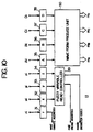
- rule address signal "ruladdr” is applied to the fuzzy rule storage 9 (Fig. 3), and its corresponding rule is read by the fuzzy rule register 11, the construction of which is shown in Fig. 10.
- the rule represented by the equation (1) which is read from the fuzzy rule storage 9 is latched and stored by latch circuits 31 through 38 (Fig. 10) for each variable.
- the address in the "r" latch circuit 31 is used through a write interface 22 (Fig. 8) as a write address signal "wad” for the fuzzy conclusion storage 20.
- the addresses in the "x", “y” and “z” latch circuits 32, 33 and 34 are converted into a time sequence by a fuzzy variable read controller 39 to be subsequently applied to an input controller 12 (Fig. 3) as a read address "rad” together with a register code "rcode".
- a construction of the input controller 12 is shown in Fig. 11.
- the signals thus fed to the input controller 12 regarding the antecedent of the rule are decoded by a pair of decoders 40 and 41. If the read address "rad" and the register code “rcode” regarding the first fuzzy variable are applied to the controller 12, the register code “rcode” is decoded by the decoder 41 and an input latch 44 is selected.
- the read address "rad” is decoded by the decoder 40 which inquires whether data should be gained from its inner part, viz., the fuzzy conclusion storage 20 (Fig. 8) or from its external part, viz., a sensor or a lower rank FC. In accordance with the result of the inquiry, an external input interface 45 or a fuzzy conclusion storage interface 46 is selected to generate an address signal regarding the fuzzy variable x.
- the selection of the interface 45 or 46 is made by the status that a predetermined bit in the read address "rad" is "1" or "0". If the conclusion storage interface 46 is selected, an address signal "fmad" regarding the fuzzy variable x is produced from the interface 46, and the fuzzy conclusion storage 20 (Fig. 8) through an input controller interface 225 to read the data from the storage 20. The read data is applied to the fuzzy conclusion storage interface 46 (Fig. 11) as a signal “fdat" through the input controller interface 225.
- the interface 45 produces a select signal" sensad" for sensor 6 or lower rank FC.
- the selected sensor or FC sends back to the interface 45 a status signal or a fuzzy reasoned result as a signal "sdat".
- the data entered into the fuzzy conclusion storage interface 46 and sent to the external input interface 45 are set through a line 47 into an input latch 42 as a signal "dx".
- the same operations are made regarding the variables y and z, and fuzzy variable values dy and dz are set into the input latches 43 and 44.
- fuzzy variable values dx, dy and dz execute a reasoning together with another signal, viz., a membership function.
- a construction for generating the membership functon will be set out below.
- labels A, B, C and D of membership functions of fuzzy rules are latched for storage in the latch circuits 35, 36, 37 and 38 as set forth above.
- latched labels A, B, C and D are appplied to a waveform produce unit 50 as a part of an address thereto, and the unit 50 generates signals representing functions in a time dependent type as described below.
- the waveform produce unit 50 generates fuzzy membership functions.
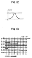
- the fuzzy membership function is represented by a continuance function having at its abscissa a fuzzy variable and at its ordinate a belongings degree.
- the fuzzy computer in this embodiment generates a membership function shown in Fig. 13 wherein the fuzzy variable x is provided in a dispersed fashion and the respective belongings degrees are represented by pulse lengths having the simultaneous terminal points (viz., pulse widths), which is called as the PWM (Pulse Width Modulation) expression of the membership function.
- PWM Pulse Width Modulation
- Fig. 14 shows a detailed constructin of the waveform produce unit 50 which stores function forms of a pluratity of kinds of membership functions.
- Waveform storage 51, 52, 53 and 54 store functions to be selected corresponding to the labels (A, B, C, D ... ) playing input signals, and a counter 55 controles a reading timing for the selected function.
- the waveform storages 51 through 54 store a plurality of membership functions represented by the PWM expression having at its lattice "0" or "1" as shown in Fig. 13 in the order of labels. Accordingly, if a membership function is designated by a label and a count value is applied by the counter 55 counting clock pulses, the waveform storages 51 to 54 are accessed in the order of time, t0, t1, t2, t3 ... , as shown in Fig. 13, and a membership functon represented by pulse lengths is generated on lines h0, h1, h2 ... hn as shown in Fig. 15.
- a fuzzy reasoning is executed by the fuzzy variable values dx, dy and dz and the membership functions (mA, mB, mC and mD).
- Fig. 16 there is shown a schematic construction of the fuzzy reasoning unit 14 of Fig. 3.
- the fuzzy reasoning unit 14 processes an antecedent of a fuzzy rule. That is, input membership functions mA, mB and mC represented by PWM on a plurality of lines h0, h1, h2 ... hn (see Fig. 15) are connected to multiplexers 61, 62 and 63 which select one of the lines h0, h1, h2 ... hn in accordance with the magnitudes of the fuzzy variables dx, dy and dz to generate belongings degrees ex, ey and ez.
- This is equivalent to the operation that a conventional fuzzy computer evaluates an input signal from sensors or the like in a membership function to generate a belongings degree.
- the conventional fuzzy computer expresses the belongings degree by the potential or current magnitudes of electronic signals, but the computer in this embodiment expresses it by pulse widths.
- the belongings degrees or values ex, ey and ez are operated by a minimum circuit 64 about a MIN operation.
- the minimum curcuit 64 is constructed by a simple AND circuit shown in Fig. 17. Since the belongings values ex, ey and ez are represented by PWM, the AND circuit can easily select the pulse having the narrowest pulse width (belongings value) in the MIN operation to produce an output g.
- the truncation section 65 is constituted with an AND circuit group connected in a parallel relationship shown in Fig. 18, in which one input terminals of the respective AND circuits are commonly connected with the output terminal of the minimum circuit 64 to be fed with the output g representing the shortest pulse width signal.
- truncation section 65 Other inputs of the truncation section 65 are the membership function mD at the consequent, which is represented by the pulse widths on the prularity of lines h0, h1, h2 ... hn.
- the truncation section 65 selects the narrower width of pulse in the pulse signals to generate an output mD' which is represented by "n" lines corresponding to the input mD. This is similar to the so-called truncating operation in the conventional fuzzy computer.
- the result mD' of the execution is read by a shift register group 68 reset in its initial status through a C-maximum circuit 66 and a bus 67 consisting of n lines.
- the shift register group 68 is constituted with n sets of shift registers, which reappearably stores pulse width signals represented by the above-mentioned PWM type.
- the C-maximum circuit 66 includes n sets of two-input OR circuits in parallel corresponding to the above-mentioned number of lines. Accordingly, the respective pulse signals of the output mD' are stored into the shift register group 68 as they are after the execution by the first rule.
- the output mD' is synchronized with the timing applied to the C-maximum circuit 66 and applied by the reappeared execution result by the first rule from the shift region group 68, and the signal having the longer pulse width is selected for "n" linen and stored into the shift register group 68 as set out above. This is equal to the operation of the so-called MAX operation by the conventional fuzzy computer.
- Fig. 20 shows a construction of a defuzzifier 69 to carry out the defuzzify operation
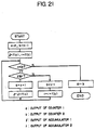
- Fig. 21 shows a flow chart in the defuzzifier 69.
- the execution result stored in the shift register group 68 (Fig. 16) is read through a bus 67 into n pieces of shift registers 700 through 70 n-1 for each line.
- the execution result expressed by PWM is stored in a transcribed manner.
- the storage status is illustratively shown in Fig. 22.
- shift registers 70 read data in a serial mode as described above, but generate an output as a parallel signal.
- This parallel signal provides the above-described PWM mode execution result, for example, the height of wave form 73 in Fig. 22.
- the defuzzify operation in this fuzzy computer is executed by defining as an affirmed value the point which equally divides the area of the above-mentioned waveform 73 of Fig. 22, right and left.
- This defuzzify operation will be briefly described hereinafter.
- a left-hand partial area of the waveform is successively calculated by adding (accumulating) the wave height of the waveform in the direction from the left hand to the direction a, while a right-hand partial area of the waveform is also similarly calculated from the right hand to the direction b.
- the respective partial areas are compared to detect their coincedence. If there is no coincidence, the smaller area side is calculated by the above addition and the result of this addition is reviewed as to the above comparison.
- the defuzzified output 74 is eventually gained.
- left and right counters 75 and 76 are preset to "0" and "n-1", respectively, so that the left-end shift register 700 and the right-end shift register 70 n-1 are designated (addressed). Then accmulators 77 and 78 are reset. As a result, through a lead controller 71 the left-end shift register 700 is addressed and the data f (0) is produced on data bus 79. This produced data is added to the contents in the accumulator 77, and the addition result is stored in the accumulator 77.
- a comparator 300 compares the value "1" of the accumulator 77 with the value "r" of the accumlulator 78, so that it drives an accumulation controller 301 if 1 ⁇ r and in accumulation controller 302 if 1 > r.
- an up-counter 75 or a down-counter 76 is fed with an enable signal.
- the up counter 75 Upon receiving the enable signal the up counter 75 adds "1" to a stored value "a” to drive the lead controller 71 which designates the shift register corresponding to the value "a" of the up-counter 75. The data of the designated shift register is added into the accumulator 77.
- the down counter 76 Upon receiving the enable signal, the down counter 76 subtracts "1" from the stored value "b” to drive the lead controller 72 which designates the shift register corresponding to the value "b" of the down counter 76. The data in the designated shift register is added into the accumulator 78.
- the comparator 303 receiving the outputs from the counters 75 and 76 detects the value of counter 75 exceeding the value of counter 76 to open a gate 305.
- the data stored in the counter 76 is produced as an affirmed value "dr".
- the gate 305 is opened, the accumulated value in the accumulator 77 is nearly equal to that in the accumulator 78 within the range of clearance.
- the affirmed value viz., the conclusion value dr is stored into the fuzzy conclusion storage 20 (Fig. 8) through the write interface 224 wherein the address stored in the r latch circuit 31 given by the MPU1 is used.
- the affirmed or decided value stored in the fuzzy conclusion storage 20 is read out from the same fuzzy conclusion storage 20 through the conclusion storage data register 25 for application to the conclusion data register 251 for subsequent use when the request for a same defuzzified output is subsequently made (Fig. 23).
- a fuzzy variable X1 having a decided value C is stored in the storage 20.
- the stored value in the past reasoning is read from the storage 20. If a value stored in the fuzzy conclusion storage 20 appears on the antecedent in the subsequent reasoning as a variable, the value is used for executing the reasoning at the antecedent (Figs. 24).
- a fuzzy variable Z1 having a value C is stored in the storage 20.
- Fig. 23(b) if the stored value of the variable Z1 is found at an antecedent in a later reasoning, it is used in the later reasoning.
Landscapes
- Engineering & Computer Science (AREA)
- Software Systems (AREA)
- Theoretical Computer Science (AREA)
- General Physics & Mathematics (AREA)
- Physics & Mathematics (AREA)
- Computational Mathematics (AREA)
- Evolutionary Computation (AREA)
- Molecular Biology (AREA)
- Fuzzy Systems (AREA)
- Biomedical Technology (AREA)
- Algebra (AREA)
- Artificial Intelligence (AREA)
- Health & Medical Sciences (AREA)
- Data Mining & Analysis (AREA)
- General Health & Medical Sciences (AREA)
- Automation & Control Theory (AREA)
- Mathematical Analysis (AREA)
- Mathematical Optimization (AREA)
- Pure & Applied Mathematics (AREA)
- Computing Systems (AREA)
- General Engineering & Computer Science (AREA)
- Mathematical Physics (AREA)
- Life Sciences & Earth Sciences (AREA)
- Feedback Control In General (AREA)
- Devices For Executing Special Programs (AREA)
Applications Claiming Priority (3)
| Application Number | Priority Date | Filing Date | Title |
|---|---|---|---|
| JP248662/88 | 1988-09-30 | ||
| JP63248662A JP2605828B2 (ja) | 1988-09-30 | 1988-09-30 | 情報処理システム並びにファジィコンピュータ |
| EP19890118094 EP0361521A3 (fr) | 1988-09-30 | 1989-09-29 | Système de calculateur déductif |
Related Parent Applications (2)
| Application Number | Title | Priority Date | Filing Date |
|---|---|---|---|
| EP89118094.5 Division | 1989-09-29 | ||
| EP19890118094 Division EP0361521A3 (fr) | 1988-09-30 | 1989-09-29 | Système de calculateur déductif |
Publications (1)
| Publication Number | Publication Date |
|---|---|
| EP0624840A1 true EP0624840A1 (fr) | 1994-11-17 |
Family
ID=17181471
Family Applications (1)
| Application Number | Title | Priority Date | Filing Date |
|---|---|---|---|
| EP94110208A Withdrawn EP0624840A1 (fr) | 1988-09-30 | 1989-09-29 | Système de calculateur déductif |
Country Status (2)
| Country | Link |
|---|---|
| EP (1) | EP0624840A1 (fr) |
| JP (1) | JP2605828B2 (fr) |
Families Citing this family (3)
| Publication number | Priority date | Publication date | Assignee | Title |
|---|---|---|---|---|
| US5583989A (en) * | 1992-05-28 | 1996-12-10 | Honda Giken Kogyo Kabushiki Kaisha | Vehicle control system having program generator and convertor |
| JPH06202870A (ja) * | 1992-12-28 | 1994-07-22 | Nec Corp | 推論規則を学習するファジイ推論システム |
| JP4194108B2 (ja) | 2001-10-12 | 2008-12-10 | オムロン株式会社 | 情報処理装置、センサネットワークシステム、情報処理プログラム、および情報処理プログラムを記録したコンピュータ読み取り可能な記録媒体 |
Citations (1)
| Publication number | Priority date | Publication date | Assignee | Title |
|---|---|---|---|---|
| EP0268182A2 (fr) * | 1986-11-13 | 1988-05-25 | Omron Tateisi Electronics Co. | Calculateurs flous |
Family Cites Families (4)
| Publication number | Priority date | Publication date | Assignee | Title |
|---|---|---|---|---|
| JPS6014303A (ja) * | 1983-07-04 | 1985-01-24 | Hitachi Ltd | 知識ベ−ス型診断方式 |
| JPS6238934A (ja) * | 1985-08-14 | 1987-02-19 | Hitachi Ltd | 双方向推論処理方式 |
| JPS62208133A (ja) * | 1986-03-10 | 1987-09-12 | Shigeo Ishii | 推論方式 |
| JPS62256128A (ja) * | 1986-04-30 | 1987-11-07 | Toshiba Corp | 推論方式 |
-
1988
- 1988-09-30 JP JP63248662A patent/JP2605828B2/ja not_active Expired - Fee Related
-
1989
- 1989-09-29 EP EP94110208A patent/EP0624840A1/fr not_active Withdrawn
Patent Citations (1)
| Publication number | Priority date | Publication date | Assignee | Title |
|---|---|---|---|---|
| EP0268182A2 (fr) * | 1986-11-13 | 1988-05-25 | Omron Tateisi Electronics Co. | Calculateurs flous |
Non-Patent Citations (3)
| Title |
|---|
| GUPTA ET AL: "Fuzzy Computing", February 1988, ELSEVIER SCIENCE PUBLISHERS B.V., AMSTERDAM, NORTH HOLLAND * |
| SADAYAPPAN AND SMITH: "Task distribution on a hierarchical multicomputer", PROC. COMPCON84 FALL, September 1984 (1984-09-01), pages 406 - 415, XP002090363 * |
| TOGAI ET AL: "Expert System on a Chip: An Engine for Real-Time Approximate Reasoning", IEEE EXPERT, vol. 1, no. 3, 1986, NEW YORK US, pages 55 - 62, XP011361089, DOI: doi:10.1109/MEX.1986.4306980 * |
Also Published As
| Publication number | Publication date |
|---|---|
| JP2605828B2 (ja) | 1997-04-30 |
| JPH0296236A (ja) | 1990-04-09 |
Similar Documents
| Publication | Publication Date | Title |
|---|---|---|
| Boutilier et al. | Computing optimal policies for partially observable decision processes using compact representations | |
| US5249258A (en) | Reasoning computer system | |
| US5606646A (en) | Recurrent neural network-based fuzzy logic system | |
| Lin et al. | Reinforcement learning with hidden states | |
| Boutilier et al. | Exploiting structure in policy construction | |
| Fung et al. | Backward simulation in Bayesian networks | |
| US5165011A (en) | System for switching a rule group | |
| US5363472A (en) | Reasoning computer system | |
| US5467426A (en) | Digital fuzzy inference apparatus having time-divisional control function | |
| JPH05189400A (ja) | 畳込みエキスパート神経システム | |
| EP0361521A2 (fr) | Système de calculateur déductif | |
| Schmitt | Computational aspects of three-valued logic | |
| Großmann et al. | Symbolic dynamic programming within the fluent calculus | |
| JPH0329034A (ja) | トートロジーチェック装置 | |
| Bader et al. | The integration of connectionism and first-order knowledge representation and reasoning as a challenge for artificial intelligence | |
| Shubin et al. | Categorical Analysis of Logical Networks in Application to Intelligent Radar Systems | |
| US5497449A (en) | Fuzzy inference apparatus | |
| JP2605828B2 (ja) | 情報処理システム並びにファジィコンピュータ | |
| US5704010A (en) | Arrangement for rule decoding and evaluation for a high-resolution fuzzy inference processor | |
| JPH07319703A (ja) | 多数のファジイ論理推論規則の並列処理法及びその回路構成 | |
| US5778149A (en) | Defuzzification device for a high-resolution fuzzy logic controller | |
| Chen | A study on the timeliness property in real-time systems | |
| JP2785280B2 (ja) | ファジィ推論装置および情報処理装置 | |
| JP2605829B2 (ja) | フアジイ推論方法及びファジイ推論装置 | |
| US5292996A (en) | Microcomputer with function to output sound effects |
Legal Events
| Date | Code | Title | Description |
|---|---|---|---|
| PUAI | Public reference made under article 153(3) epc to a published international application that has entered the european phase |
Free format text: ORIGINAL CODE: 0009012 |
|
| 17P | Request for examination filed |
Effective date: 19940630 |
|
| AC | Divisional application: reference to earlier application |
Ref document number: 361521 Country of ref document: EP |
|
| AK | Designated contracting states |
Kind code of ref document: A1 Designated state(s): AT BE CH DE ES FR GB GR IT LI LU NL SE |
|
| STAA | Information on the status of an ep patent application or granted ep patent |
Free format text: STATUS: THE APPLICATION IS DEEMED TO BE WITHDRAWN |
|
| 18D | Application deemed to be withdrawn |
Effective date: 20000331 |