EP0624848A2 - Technique pour la detection et lacorrection des défauts locaux dans des images à tons continus - Google Patents
Technique pour la detection et lacorrection des défauts locaux dans des images à tons continus Download PDFInfo
- Publication number
- EP0624848A2 EP0624848A2 EP94106449A EP94106449A EP0624848A2 EP 0624848 A2 EP0624848 A2 EP 0624848A2 EP 94106449 A EP94106449 A EP 94106449A EP 94106449 A EP94106449 A EP 94106449A EP 0624848 A2 EP0624848 A2 EP 0624848A2
- Authority
- EP
- European Patent Office
- Prior art keywords
- value
- defects
- image
- pixel
- defect
- Prior art date
- Legal status (The legal status is an assumption and is not a legal conclusion. Google has not performed a legal analysis and makes no representation as to the accuracy of the status listed.)
- Withdrawn
Links
Images


Classifications
-
- G—PHYSICS
- G06—COMPUTING OR CALCULATING; COUNTING
- G06T—IMAGE DATA PROCESSING OR GENERATION, IN GENERAL
- G06T5/00—Image enhancement or restoration
- G06T5/70—Denoising; Smoothing
-
- G—PHYSICS
- G06—COMPUTING OR CALCULATING; COUNTING
- G06T—IMAGE DATA PROCESSING OR GENERATION, IN GENERAL
- G06T5/00—Image enhancement or restoration
- G06T5/20—Image enhancement or restoration using local operators
- G06T5/30—Erosion or dilatation, e.g. thinning
-
- G—PHYSICS
- G06—COMPUTING OR CALCULATING; COUNTING
- G06T—IMAGE DATA PROCESSING OR GENERATION, IN GENERAL
- G06T5/00—Image enhancement or restoration
- G06T5/77—Retouching; Inpainting; Scratch removal
-
- G—PHYSICS
- G06—COMPUTING OR CALCULATING; COUNTING
- G06V—IMAGE OR VIDEO RECOGNITION OR UNDERSTANDING
- G06V10/00—Arrangements for image or video recognition or understanding
- G06V10/98—Detection or correction of errors, e.g. by rescanning the pattern or by human intervention; Evaluation of the quality of the acquired patterns
-
- G—PHYSICS
- G06—COMPUTING OR CALCULATING; COUNTING
- G06T—IMAGE DATA PROCESSING OR GENERATION, IN GENERAL
- G06T2207/00—Indexing scheme for image analysis or image enhancement
- G06T2207/10—Image acquisition modality
- G06T2207/10004—Still image; Photographic image
- G06T2207/10008—Still image; Photographic image from scanner, fax or copier
-
- G—PHYSICS
- G06—COMPUTING OR CALCULATING; COUNTING
- G06T—IMAGE DATA PROCESSING OR GENERATION, IN GENERAL
- G06T2207/00—Indexing scheme for image analysis or image enhancement
- G06T2207/10—Image acquisition modality
- G06T2207/10024—Color image
-
- G—PHYSICS
- G06—COMPUTING OR CALCULATING; COUNTING
- G06T—IMAGE DATA PROCESSING OR GENERATION, IN GENERAL
- G06T2207/00—Indexing scheme for image analysis or image enhancement
- G06T2207/20—Special algorithmic details
- G06T2207/20036—Morphological image processing
-
- G—PHYSICS
- G06—COMPUTING OR CALCULATING; COUNTING
- G06T—IMAGE DATA PROCESSING OR GENERATION, IN GENERAL
- G06T2207/00—Indexing scheme for image analysis or image enhancement
- G06T2207/20—Special algorithmic details
- G06T2207/20172—Image enhancement details
- G06T2207/20192—Edge enhancement; Edge preservation
Definitions
- the present invention is related to the field of scanning images, primarily from photographic film, to form electrical equivalents of the scanned images and more particularly to the detection and the removal of defects due, for example, to dirt contamination or physical damage of the film.
- Digital images created from electronic scanning of continuous-tone photographic film often reveal visually objectionable defects due to dirt contamination or surface damage of the film. These defects usually must be digitally corrected by manual digital retouching (e.g. via "dustbusting” and other cloning techniques), which require that the operator visually identify each local defect in the image.
- a significant problem in the detection of dust is to provide an adequate way of detecting "small" objects.
- This approach while possible, has the drawback that the color classification must be quite accurate, or else some marginally-colored pixels will be misclassified.
- the problem is that differences in the direct RGB (or luminance-chrominance) image values do not alone give much contrast information between, say, a white small dust artifact and a bright grey extended scene region on which the artifact is superimposed. Thus after color-classification one may be left with very large segments that are reasonably neutral and bright, but which now mask visible dust artifacts.
- a better approach prior to classification is to preselect only those points which have large local contrast from their surround. This may be directly accomplished by (1) spatially smoothing the color image and (2) subtracting the smoothed color image from the original color image.
- the resulting difference (or "residuals") image will emphasize all color pixels which have a large magnitude compared to some weighted local average magnitude.
- the key decision here is then the choice of spatial smoother.
- the most obvious first candidate is a low-pass linear filter (e.g. a simple spatially weighted averaging of all grey levels (GLs) in a local window); the properties may be easily analyzed mathematically, and (perhaps more important) such filters may be rapidly implemented in software and hardware (the residual image is basically a high-pass-filtered version of the original).
- linear residuals images have the property of retaining all local edges in an image, including very long edges due to scene discontinuities. The result is a very "cluttered" image (i.e. the residuals image contains many bright pixels having no connection with dirt or scratches); a significant amount of additional time must then be spent in scene reasoning to clean up the residuals map before defect decisions can be made. In short, linear-filter residuals poorly discriminate between local defects and true scene details.
- the identification of anomalies such as dust or scratches leads to the desirability of removing the same without the intervention of an operator.
- the present invention is directed to a methodology for identifying and cosmetically correcting such anomalies with minimal operator intervention.
- a method for the detection and removal of defects in digital images comprising the steps of:
- the present method is called an autodustbuster (ADB) algorithm, and it has been successfully tested on both consumer-type color photographic images and color motion picture frames with good results.
- ADB autodustbuster
- Figure 1 illustrates a system on which the present invention may be implemented.
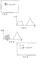
- Figure 2 illustrates the windowing of an image raster to determine the grey level of a central pixel GLc at a position X.
- Figure 3 illustrates in chart form a histogram of GL values for an associated window.
- Figure 4 illustrates the averaging of the samples "nearest" in grey level GL to the central pixel GLc for the histogram of Figure 3.
- Figure 5 illustrates the replacement of the GLc value with the grey level average GL av at the position X.
- Figure 6 illustrates the process flow for a multi-band original image.
- Figure 7 illustrates the process flow for a resolution pyramid of an image.
- Figure 8 illustrates the process flow as applied to an R, G, B image.
- Figure 9 illustrates a flow for ADB processing within a resolution pyramid.
- the present invention is implemented using a digitizing scanner 10, a control and logic device 24, such as a computer with a display device 26, and an optical disc writer 36.
- a strip of film 15, containing one or more frames 18 of developed film is placed into a scan gate 12 where the strip of film 15 is scanned under direction of control and logic circuitry 30.
- the resultant scanned image data, represented by block 22 is digitized and transmitted to a memory 28 for storage.
- the computer 24 process the stored data, in a manner to be described, to provide output image data 32 which may be written to an optical disc 34 by the optical disc writer 36 to provide a report as to the characteristics of the anomalies.
- the scanning device 10 is capable of quantizing pixel values into multiple brightness levels in separate red, green, and blue channels.
- a minimum number of brightness levels would be approximately 64 for an adequate quality image with a typical number being 256.
- the image data 22 has been described as originating from the operation of scanning film, it is well understood that other well-known techniques may be used to provide the image data.
- ADB autodustbuster
- the required ADB operations may be divided into (1) feature selection, (2) defect detection, and (3) defect correction.
- the operations must ensure that the maximum number of defects is detected and optimally corrected while minimally affecting scene elements which are not defects.
- the more confidence which the user has in the accuracy of the detection process the more extreme can be the removal process; conversely, as one's confidence in avoiding "false alarms" from scene elements diminishes, milder removal methods may be used to avoid damaging real scene elements.
- Visible dirt artifacts in digital positives created from scanned color negatives, possesses the following properties: they are "white” (low color saturation), “bright” (very high apparent exposure values), “small” (small spatial extent) and “contrast” (large differences from their immediate surround). (If dirty color positives were instead scanned, then the dirt artifacts would be “dark” rather than “bright”). In addition, many such fragments exhibit little brightness variation within individual defects.
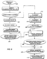
- FIG. 2 illustrates in flow chart form the generic autodustbuster process flow.
- the original image of block 100 is a multi-band digital image represented by one or more matrices of pixel values or equivalently grey levels (GL).
- preprocessing block 110 some effective and convenient remapping of the original image may be performed.
- An example of preprocessing is the digital resampling of the image to reduce its size for computational expediency.
- An alternate preprocessing is the selection or recombination of the original image bands to produce a feature image with fewer bands.
- the detection suitability of the resulting feature image, in any case, should be at least comparable to that of the original image.
- Oval 120 represents the feature image that is outputted from block 110.
- the feature image is subjected to a band brightness test in block 130.
- the test applies low and high threshold evaluations to every pixel of each band in the feature image. Pixel values that are above the high threshold or below the low threshold in each band are considered to have passed the test and are forwarded to an edge-preserving-smoothing (EPS) filter 140.
- EPS edge-preserving-smoothing
- This filter non-linearly smoothes the selected pixel in all bands in a manner that retains major scene edges as subsequently described.
- the output of the filter at this pixel position is written to a corresponding position in the smoothed image 142. For those pixel values that are below the high threshold value, but above the low threshold value no subsequent EPS filtering is applied, i.e. the test is considered failed.
- Each band of the feature image pixel is copied to the resultant output of the smoothed image 142 and does not undergo EPS filtering.
- the pixel values of each band of the smoothed image are subtracted from the pixel values at the corresponding position in the feature image 120 resulting in the residuals image 148.
- the residuals test consists of a minimum and a maximum threshold that is applied to each band of the residuals image 148.
- the minimum threshold When bright defects are to be detected, for a pixel to pass all band values must exceed the minimum threshold and at least one band value must exceed the maximum threshold.
- a dark defect When a dark defect is to be detected a pixel will pass if all band values are less than the maximum threshold and at least one band value is less than the minimum threshold.
- Pixels that pass are forwarded to a classmap 160 and marked with a distinctive value.
- the classmap 160 is a single band image representation which is used to mark the location of detected defects. Pixels that fail are marked with a different value in the classmap 160.
- the values within the classmap 160 may be further modified to accommodate known spatial characteristics of the defects. For example, a one-pixel morphological dilation of the defect-marked (passed) pixels in the classmap is typically performed.
- the conditioned classmap 175 is directed to the cleaning block 180 long with the original image pixel values. Pixels in the original image that are not marked as passed in the classmap will be copied unchanged to the output cleaned image 190. Pixels which are marked as passed, i.e., defect, are corrected using neighboring non-defect pixel values. The corrected values are then written to the cleaned image 190.
- the feature image 120 used to detect the defect locations may be different from the original image 100 which will be corrected. This is generally advantageous when computational time is at a premium and EPS filtering 140 of the full (generally three-color) image is too burdensome. In this case it is often possible to apply a preprocessing module 110 to create a one- or two-band "feature" image 120 which instead will be EPS-filtered and classified for defects. The effectiveness of this strategy will depend on the success with which a reduced-dimensionality feature image will retain the size, brightness, contrast, and color defect discrimination of the original image 100. This will of course be application-specific.
- defects may be of any color and saturation; thus little is lost in detection performance using a reduced-dimension space which sacrifices color and saturation information.
- good success has been achieved in using a "band-maximum" one-band feature image 120 band where every feature pixel value is the maximum value of the input red, green, and blue bands.
- the principle source of defects is dirt on the negative during scanning, which appears as "white” specks in the digital positive; here saturation information should be retained as an important identifier, and two- or three-band EPS-filtered feature images are the norm.
- Figure 7 illustrates the retention of all three color original color bands for classification.
- Rescaling of the feature image grey-level range during preprocessing 110 is often advantageous. In current implementations this consists of linearly scaling to a 0-255 pixel value range even for 10- or 12-bit original data. This results in a slight speed improvement during EPS-filtering 140 when the histogram is searched at every window location (see Figures 4 and 5 along with associated discussions).
- this rescaling may be determined by finding .5% and 99.5% cumulative histogram points of the color-corrected bands of the entire input image. The minimum .5%-point and maximum 99.5%-point from among all bands are mapped to 0 and 255 pixel values, respectively in the feature image, thus ensuring that no color shift occurs. If the input data is not color balanced it may be necessary to perform a color balancing step on the original data.
- a smoothing filter which retains extended image edges but smoothes small local contrasty image regions (blobs).
- Such filters exist as various nonlinear noise-reduction methods under the category of "edge-preserving smoothers" (EPS).
- EPS edge-preserving smoothers
- the most widely known EPS filter is the median filter, which is one member of the class of rank-order filters.
- rank-order filters the pixel magnitudes are sorted and an average of some contiguous number of the sorted magnitudes is computed. For example, in a median filter the "middle" element of the sorted magnitudes is retained (an average over one sample).
- the sample mean is, at the other extreme, also a rank-order filter (although a poor EPS); it provides the average of all sorted magnitude values.
- a poor property of standard rank-order filters for image operations is that they are insensitive to the relative spatial location of the pixels within the current window; e.g. the magnitude chosen as the "median" may exist at the center of the window or at an extreme edge of the window.
- a number of specialized nonlinear window operators have-been devised to account for local spatial structure.
- One example is the sigma filter (J.-S. Lee, CVGIP,24,255-269. 1983). In this filter a histogram is created of the grey levels in a sliding window; based upon an estimate of the image noise, a range of histogram values about the grey level of the pixel at the center of the window is computed.
- the sigma filter is specifically designed for noise removal and its averaging range is solely dependent on the noise characteristics; the filter averages over a different number of pixels at each window location.
- noise detection what is desired is a filter whose parameters are sensitive to local shape characteristics.
- a relative of the sigma filter which gives this control is the k-nearest-neighbor (kNN) filter (Davis and Rosenfeld, IEEE Trans, SMC, 7, 107-109 ,1978).
- This filter is implemented in the EPS filter module 140 of Figure 2.
- This filter has the following operation per color band: Referring to Figure 3, slide a rectangular window of odd dimensions n x m over an image in raster order. At each location determine the grey level of the center pixel (GL c ) or equivalently pixel value, and also create a histogram of the grey levels in the local window as per Figure 4.
- sum contents of the histogram bins on both sides of the starting bin in the following fashion: Test if the contents in the bin for GL c are greater than or equal to k pixels. If this is true, then write out as the averaged value GL av just the existing value GL c . If the contents for bin GL c are less than k, then add the contents of the bin immediately below the bin and above GL c to the sum and, again test whether the sum is greater than or equal to k. If the sum equals k, then calculate the average grey level according to the formula where the index i is over the summed histogram bins.
- the extreme bins in the sum are proportionally reduced in weight in the calculation for GL av so that the total bin weight in the sum approximately equals k (as shown in the attached source code). If the sum is less than k, then the next bin below GL c and above GL c are summmed and tested against k. This process is repeated until the sum of histogram bins about GL c are greater than or equal to k. Continue until k pixels (k ⁇ n x m) have been summed. Find the average grey level of the summed pixels per Figure 5 and write this value to an output image at the location of the window center per Figure 6.
- the k-nearest neighbor filter has some interesting filtering properties which are not immediately obvious from the above description.
- any constant-GL image structure (blob) which has an area of k or more pixels in the local window will not be significantly smoothed; any structure of less than k pixels will be increasingly smoothed as k decreases.
- the first property is the one of significance for "blob" detection. For example, if the window size is 5 x 5 pixels, and if k is, say, 15, then extended straight edges having a depth (constant pixel value in both directions perpendicular to the edge) greater than three pixels will be effectively unchanged, and thus disappear in a residuals image. "Blobs" of area less than 15 pixels that fit entirely in the window will be smoothed and thus will appear strongly in the residuals image. This is the desired residuals property for a local defect detector.
- a major concern for a k-nearest neighbor filtering is computational speed. This is not a linear filter and it is not separable, nor does it have other usable symmetry properties.
- the major operations per window location are histogram creation and then accumulation with testing of the total accumulated samples.
- the current k-nearest neighbor implementation does significantly reduce the cost of computing the histogram by merely updating the window histogram in a horizontal strip of image rather than performing complete calculations per window. This results in a fractional saving of approximately (n-2)/n in histogram-computing operations (for a n pixel x m line window), i.e. the savings increase as window length increases. (This fast histogram updating is equivalent to that used in the "fast-median" filter--Huang and Tang, IEEE Trans, ASSP, 27, 13-18, 1979).
- a residuals image 148 is created as shown in Figure 2.
- the anomaly classifier steps contained in modules 150 and 170 accept as input the residuals image 148 and create as output the final classmap 175 which marks the pixels to be cleaned.
- the residuals test in module 150 creates an initial classmap by performing tests on each pixel of the residuals image 148.
- a spatial segmentation i.e. connected-component labeling
- additional tests applied to the same segment may be optionally performed with additional tests applied to the same segment.
- each color residual pixel is evaluated against two residual-GL thresholds, GL rmin and GL rmax .
- all color residual pixels whose minimum band residual GL exceeds GL rmin and whose maximum band residual GL exceeds GL rmax are uniquely marked for subsequent cleaning; pixels which do not satisfy both of these constraints are marked to be left unaltered in the output image.
- GL rmin equals GL rmax .
- the two-dimensional map of category markings per pixel is termed the "class map".
- the (smaller) GL rmin threshold is generally set slightly above the "zero point" in the residuals image (e.g. to 133 for rescaled features with residuals biased by a value of 128 as described above) and acknowledges that valid bright defect pixels , e.g. due to dirt on a scanned negative, should not have a negative contrast (residual values less than the zero point) in any band.
- the (larger) GL rmax threshold states a requirement of significant local contrast in at least one band for the defect to be visible.
- the minimum-residuals thresholds are set equally, and slightly above the zero point as mentioned above; the maximum-residuals threshold is set somewhat higher for labeling high-confidence pixels than is the maximum-residuals threshold for the low-confidence pixels.
- This labeling results in a class map where the pixels possess one of three labels (normal, low-confidence dirt, and high-confidence dirt). In two-state classification, this class map undergoes image segmentation in module 170, i.e. all residuals pixels spatially contiguous in the class map which have the same class are, assigned a unique code value.
- all segments which contain low-confidence defect pixels and which are spatially touching segments containing high-confidence pixels are upgraded to high-confidence (i.e. the class map values of the pixels are reassigned to the "high confidence of an defect" class).
- the purpose of this step is to make use of the adjacent presence of very obvious defects to decide that a slightly less contrasty region is part of the same defect.
- the segments which remain at low confidence are either relabeled as "clean” (i.e. all pixels of the segment are marked for no cleaning in the classmap) or else name their pixels marked for subsequent cleaning state in module 180.
- the segments, which are marked as high confidence of being defects have their pixels marked in the classmap for subsequent erosion cleaning in module 180.
- EPS substitution Two general cleaning methods are presently available for use within module 180 in the ADB algorithms: EPS substitution and greyscale erosion.
- simple EPS substitution the original input multi-band grey levels of image 100 are simply replaced by the band EPS-filtered grey levels of smoothed image 142 wherever a pixel is marked as a defect in the classmap 175 (as shown in Figure 2).
- This method has the advantage of computational simplicity in that EPS values have already been computed during defect detection; however it requires that the EPS image be stored for use during cleaning.
- EPS substitution is relatively forgiving of "false alarms", i.e. pixels classified as dirt artifacts but which are really part of the scene.
- EPS-substitution cleaning may not completely remove all of an extended defect, to the degree that the defect itself influenced the local EPS values.
- the second precaution is that the spatial window over which the erosion weights are taken should be kept reasonably small, e.g. 5 x 5 samples. The reason for this is to minimize the influence of distant pixels which may not be part of the same scene structure as the region obscured by the central defect pixel.
- the erosion cleaner is to use a 5x5-pixel sliding window with a minimum of six clean-class contained pixels in order for a central defect-class pixel to be filtered; if the central pixel is defect-class, but fewer than six clean samples are contained, then the defect classification is maintained to the next iteration. If the central pixel is of defect class and six or more clean-class samples are contained in the window, then the GLs of the central pixel are replaced by a weighted average of the band GLs of the contained clean pixels, where the weights are linearly proportional to the inverse of the Euclidean spatial distance of the clean pixel from the central pixel.
- the cleaning is iterative (multiple passes through the class map) but is not recursive, i.e. the cleaning effect at one window location does not affect the cleaning at subsequent locations during the same iteration, in order to avoid directional biasing.
- Greyscale erosion has the advantage over EPS-substitution in being able to completely eliminate all trace of the artifact from the image; its disadvantages are increased complexity, a variable processing rate (the number of iterations is not known a priori), and the possibility for severe scene damage in the case of "false alarms" (i.e., real scene elements may be removed from the image). Despite these concerns, the excellent cleaning performance of erosion is currently the preferred method in both Photo CD ( Figure 7) and Cineon ( Figure 8) applications.
- the ADB algorithm has several "flavors”. These include (a) operation at a single spatial resolution, (b) operation within a resolution pyramid, (c) single-defect-state detection, (d) multiple-defect-state detection, and cleaning via (e) EPS substitution or (f) grey scale erosion.
- all pixels of the image are classified as either "non-defect” or "defect”, i.e. only one defect state is treated.
- the "defect" classification is further divided into subclassifications depending on the confidence that a pixel is indeed a defect; thus a three-state classification would consist of "non-defect", "high-confidence defect", and "transition-confidence defect".
- the cleaner used is either EPS-substitution or grey-scale erosion, but not both in one implementation.
- the multi-state version may employ a combination of both EPS-substitution for cleaning the lower-confidence defect regions and grey-scale erosion for cleaning the higher-confidence defect regions.
- the flavor combining options (a), (c), and (f) is a simple variant to implement, though it is not necessarily the fastest or best-performing version.
- no spatial resolution pyramid is formed, the residuals image is not segmented, and the cleaner is chosen to be gray scale erosion for maximum correction.
- Figure 7 illustrates such a process flow and is typical of a Photo CD application.
- the preprocessing 110 consists of rescaling the pixel values of the original image for maximum viewing contrast by linearly remapping the lowest .5-% band gray level to a value of zero and the highest 99.5% level to 255, as previously described in the description for Figure 2.
- the brightness test 130 for dirt on scanned negatives consists of minimum threshold pixel values which must be equaled or exceeded in each band of the feature image 120 in order for the corresponding pixel to pass the test as a possible defect.
- the residuals classification 150 is a single state decision per pixel as either a non-defect or defect class, based upon a requirement that the smallest band residual equal or exceed the zero-background residuals level and that the largest band residual equal or exceed some user-determined threshold level which is above the zero background level.
- the classmap conditioning 170 in this case consists of a morphological dilation of the defect pixels in the classmap using a 3 x 3 or 5 x 5 kernel.
- the cleaning 180 consists of greyscale erosion as previously described under the section called "cleaning.”
- Figure 8 illustrates an alternate processing flow which retains the characteristics, (a), (c) and (f), is appropriate for removal of bright defects in Cineon applications.
- the preprocessing 110 in this instance consists of creating a reduced resolution image rescaling it to a zero to 255 greylevel range such that the color balance is corrected, and then extracting a single band feature image in which the output pixel value is the larger of the Red, Green and Blue input values.
- the residuals test 150 applies a single threshold which each residuals pixel must equal or exceed to be marked as defect.
- Classmap conditioning 170 consists of morphological dilation as described above.
- the cleaning module 180 consists initially of performing greyscale erosion of the reduced resolution unrescaled input image as previously described.
- the cleaned reduced resolution multi-band image is bilinearly interpolated back to the original size and the conditioned classmap is replicated to the original image size.
- those pixels in the original image which are marked "defect" in the replicated classmap are replaced by the pixel values in the interpolated cleaned reduced resolution image.
- ADB within a multi-resolution pyramid structure to provide some speed gains from use of multiple smaller EPS kernels. This implementation would also allow more effective cleaning from the use of EPS residuals thresholds which are tuned to the specific pyramid level.
- Figure 9 illustrates a flow for ADB processing within a resolution pyramid.
- ADB cleaning within a spatial level is similar to that in a single-level ADB version, i.e. detection, classification, and cleaning occur, and choices of one- or two-state and of EPS-substitution and/or greyscale erosion are the same.
- One key difference lies in the way the spatial pyramid residuals images are processed.
- an image is represented generally as a low-resolution image plus a number of residuals images of increasing resolution.
- one interpolates the low-resolution image by a prescribed method to the next resolution level and then adds the residuals values of that level to each pixel GL. This process continues until the desired resolution level has been reconstructed.
- the Photo CD file format is an example of a spatial pyramid structure. Note that these residual images are simply the pixel band difference between the original image at that resolution and the interpolated low-resolution version; they should not be confused with the EPS residual images discussed above.
- the defect-class pixels in the replicated classmap are then dilated in module 210 by a spatial extent equal to the region of support of the pyramid smoothing function for that level, i.e., the half-width of the kernal used to create the next-lower-resolution level.
- the resulting dilated classmap 220 is then compared with the pyramid-residuals image 230; the pyramid residuals image is assigned a zero pixel value in every band wherever the corresponding pixel in the class map 220 is labeled as defect.
- the resulting modified pyramid-residuals image 250 is then added per-pixel in module 270 to a version of the base level cleaned image 190 which has been spatially interpolated to the present pyramid resolution level in module 260.
- the Invention may be summarized as follows:
Landscapes
- Engineering & Computer Science (AREA)
- Physics & Mathematics (AREA)
- General Physics & Mathematics (AREA)
- Theoretical Computer Science (AREA)
- Quality & Reliability (AREA)
- Multimedia (AREA)
- Image Processing (AREA)
- Facsimile Image Signal Circuits (AREA)
Applications Claiming Priority (2)
| Application Number | Priority Date | Filing Date | Title |
|---|---|---|---|
| US5794293A | 1993-05-04 | 1993-05-04 | |
| US57942 | 1993-05-04 |
Publications (2)
| Publication Number | Publication Date |
|---|---|
| EP0624848A2 true EP0624848A2 (fr) | 1994-11-17 |
| EP0624848A3 EP0624848A3 (fr) | 1994-11-30 |
Family
ID=22013685
Family Applications (1)
| Application Number | Title | Priority Date | Filing Date |
|---|---|---|---|
| EP19940106449 Withdrawn EP0624848A3 (fr) | 1993-05-04 | 1994-04-25 | Technique pour la detection et lacorrection des défauts locaux dans des images à tons continus |
Country Status (2)
| Country | Link |
|---|---|
| EP (1) | EP0624848A3 (fr) |
| JP (1) | JPH06333041A (fr) |
Cited By (30)
| Publication number | Priority date | Publication date | Assignee | Title |
|---|---|---|---|---|
| EP0778543A3 (fr) * | 1995-12-04 | 1998-07-08 | Eastman Kodak Company | Méthode baseé sur le gradient pour estimer les valeurs d'éléments d'image inconnus dans une image numérisée |
| EP0768621A3 (fr) * | 1995-10-16 | 1998-07-15 | Eastman Kodak Company | Méthode et appareil pour corriger des valeurs de pixels dans une image numérique |
| DE19842572A1 (de) * | 1998-09-17 | 2000-03-23 | Heidelberger Druckmasch Ag | Verfahren zur automatischen Entfernung von Bildfehlern |
| WO2001048694A1 (fr) * | 1999-12-29 | 2001-07-05 | Applied Science Fiction, Inc. | Procede et appareil de correction d'image interactive pour images fortement deteriorees |
| US6297889B1 (en) * | 1998-12-22 | 2001-10-02 | Xerox Corporation | Logic-based image processing method |
| US6380539B1 (en) | 1997-01-30 | 2002-04-30 | Applied Science Fiction, Inc. | Four color trilinear CCD scanning |
| US6393160B1 (en) | 1998-03-13 | 2002-05-21 | Applied Science Fiction | Image defect correction in transform space |
| US6437358B1 (en) | 1999-02-04 | 2002-08-20 | Applied Science Fiction, Inc. | Apparatus and methods for capturing defect data |
| US6442301B1 (en) | 1997-01-06 | 2002-08-27 | Applied Science Fiction, Inc. | Apparatus and method for defect channel nulling |
| US6487321B1 (en) | 1999-09-16 | 2002-11-26 | Applied Science Fiction | Method and system for altering defects in a digital image |
| US6498867B1 (en) | 1999-10-08 | 2002-12-24 | Applied Science Fiction Inc. | Method and apparatus for differential illumination image-capturing and defect handling |
| US6590679B1 (en) | 1998-02-04 | 2003-07-08 | Applied Science Fiction, Inc. | Multilinear array sensor with an infrared line |
| US6593558B1 (en) | 1996-05-10 | 2003-07-15 | Applied Science Fiction, Inc. | Luminance-priority electronic color image sensor |
| US6614946B1 (en) | 1999-10-08 | 2003-09-02 | Eastman Kodak Company | System and method for correcting defects in digital images through selective fill-in from surrounding areas |
| GB2389733A (en) * | 2002-05-31 | 2003-12-17 | Hewlett Packard Co | System and method for automatic descreening of digital images |
| US6683995B2 (en) | 1999-12-23 | 2004-01-27 | Eastman Kodak Company | Method and apparatus for correcting large defects in digital images |
| US6711302B1 (en) | 1999-10-20 | 2004-03-23 | Eastman Kodak Company | Method and system for altering defects in digital image |
| US6720560B1 (en) | 1999-12-30 | 2004-04-13 | Eastman Kodak Company | Method and apparatus for scanning images |
| US6750435B2 (en) | 2000-09-22 | 2004-06-15 | Eastman Kodak Company | Lens focusing device, system and method for use with multiple light wavelengths |
| US6862117B1 (en) | 1999-12-30 | 2005-03-01 | Eastman Kodak Company | Method and apparatus for reducing the effect of bleed-through on captured images |
| US6924911B1 (en) | 1999-10-12 | 2005-08-02 | Eastman Kodak Company | Method and system for multi-sensor signal detection |
| EP1562145A1 (fr) * | 2004-02-09 | 2005-08-10 | Noritsu Koki Co., Ltd. | Dispositif de traitement d'images et procédé de traitement d'images pour la correction de données d'images |
| US6987892B2 (en) | 2001-04-19 | 2006-01-17 | Eastman Kodak Company | Method, system and software for correcting image defects |
| US7164511B2 (en) | 1999-12-29 | 2007-01-16 | Eastman Kodak Company | Distinguishing positive and negative films system and method |
| CN1323542C (zh) * | 2004-02-09 | 2007-06-27 | 诺日士钢机株式会社 | 图像处理装置、方法、以及程序 |
| US7433545B2 (en) | 2004-03-03 | 2008-10-07 | Noritsu Koki Co., Ltd. | Image processing apparatus and image processing method for correcting image data |
| US7715650B2 (en) | 2005-03-10 | 2010-05-11 | Eastman Kodak Company | Method and apparatus for digital processing of images |
| CN110287968A (zh) * | 2019-07-01 | 2019-09-27 | 河南大学 | 一种基于lbp纹理的焊缝探伤底片图像造假的检测方法 |
| CN112991326A (zh) * | 2021-04-14 | 2021-06-18 | 北京铁道工程机电技术研究所股份有限公司 | 一种清洗质量评价方法 |
| CN120976181A (zh) * | 2025-08-15 | 2025-11-18 | 中国标准化研究院 | 基于ai的产品抽样检测准确度评估方法及系统 |
Family Cites Families (4)
| Publication number | Priority date | Publication date | Assignee | Title |
|---|---|---|---|---|
| US5036405A (en) * | 1986-11-19 | 1991-07-30 | Canon Kabushiki Kaisha | Image amending method |
| US4975972A (en) * | 1988-10-18 | 1990-12-04 | At&T Bell Laboratories | Method and apparatus for surface inspection |
| US5038388A (en) * | 1989-05-15 | 1991-08-06 | Polaroid Corporation | Method for adaptively sharpening electronic images |
| US5142589A (en) * | 1990-12-21 | 1992-08-25 | Environmental Research Institute Of Michigan | Method for repairing images for optical character recognition performing different repair operations based on measured image characteristics |
-
1994
- 1994-04-25 EP EP19940106449 patent/EP0624848A3/fr not_active Withdrawn
- 1994-04-27 JP JP6089064A patent/JPH06333041A/ja active Pending
Cited By (40)
| Publication number | Priority date | Publication date | Assignee | Title |
|---|---|---|---|---|
| EP0768621A3 (fr) * | 1995-10-16 | 1998-07-15 | Eastman Kodak Company | Méthode et appareil pour corriger des valeurs de pixels dans une image numérique |
| US6104839A (en) * | 1995-10-16 | 2000-08-15 | Eastman Kodak Company | Method and apparatus for correcting pixel values in a digital image |
| EP0778543A3 (fr) * | 1995-12-04 | 1998-07-08 | Eastman Kodak Company | Méthode baseé sur le gradient pour estimer les valeurs d'éléments d'image inconnus dans une image numérisée |
| US6593558B1 (en) | 1996-05-10 | 2003-07-15 | Applied Science Fiction, Inc. | Luminance-priority electronic color image sensor |
| US6442301B1 (en) | 1997-01-06 | 2002-08-27 | Applied Science Fiction, Inc. | Apparatus and method for defect channel nulling |
| US6380539B1 (en) | 1997-01-30 | 2002-04-30 | Applied Science Fiction, Inc. | Four color trilinear CCD scanning |
| US6590679B1 (en) | 1998-02-04 | 2003-07-08 | Applied Science Fiction, Inc. | Multilinear array sensor with an infrared line |
| US6393160B1 (en) | 1998-03-13 | 2002-05-21 | Applied Science Fiction | Image defect correction in transform space |
| DE19842572A1 (de) * | 1998-09-17 | 2000-03-23 | Heidelberger Druckmasch Ag | Verfahren zur automatischen Entfernung von Bildfehlern |
| DE19842572B4 (de) * | 1998-09-17 | 2005-03-24 | Heidelberger Druckmaschinen Ag | Verfahren zur automatischen Entfernung von Bildfehlern |
| US6297889B1 (en) * | 1998-12-22 | 2001-10-02 | Xerox Corporation | Logic-based image processing method |
| US6437358B1 (en) | 1999-02-04 | 2002-08-20 | Applied Science Fiction, Inc. | Apparatus and methods for capturing defect data |
| US6487321B1 (en) | 1999-09-16 | 2002-11-26 | Applied Science Fiction | Method and system for altering defects in a digital image |
| US6650789B2 (en) | 1999-09-16 | 2003-11-18 | Eastman Kodak Company | Method and system for altering defects in a digital image |
| US6498867B1 (en) | 1999-10-08 | 2002-12-24 | Applied Science Fiction Inc. | Method and apparatus for differential illumination image-capturing and defect handling |
| US6614946B1 (en) | 1999-10-08 | 2003-09-02 | Eastman Kodak Company | System and method for correcting defects in digital images through selective fill-in from surrounding areas |
| US6924911B1 (en) | 1999-10-12 | 2005-08-02 | Eastman Kodak Company | Method and system for multi-sensor signal detection |
| US6711302B1 (en) | 1999-10-20 | 2004-03-23 | Eastman Kodak Company | Method and system for altering defects in digital image |
| US6683995B2 (en) | 1999-12-23 | 2004-01-27 | Eastman Kodak Company | Method and apparatus for correcting large defects in digital images |
| US7164511B2 (en) | 1999-12-29 | 2007-01-16 | Eastman Kodak Company | Distinguishing positive and negative films system and method |
| US6704458B2 (en) | 1999-12-29 | 2004-03-09 | Eastman Kodak Company | Method and apparatus for correcting heavily damaged images |
| WO2001048694A1 (fr) * | 1999-12-29 | 2001-07-05 | Applied Science Fiction, Inc. | Procede et appareil de correction d'image interactive pour images fortement deteriorees |
| US6862117B1 (en) | 1999-12-30 | 2005-03-01 | Eastman Kodak Company | Method and apparatus for reducing the effect of bleed-through on captured images |
| US6720560B1 (en) | 1999-12-30 | 2004-04-13 | Eastman Kodak Company | Method and apparatus for scanning images |
| US6750435B2 (en) | 2000-09-22 | 2004-06-15 | Eastman Kodak Company | Lens focusing device, system and method for use with multiple light wavelengths |
| US6987892B2 (en) | 2001-04-19 | 2006-01-17 | Eastman Kodak Company | Method, system and software for correcting image defects |
| US7148998B2 (en) | 2002-05-31 | 2006-12-12 | Hewlett-Packard Development Company, L.P. | System and method for automatic descreening of digital images |
| GB2389733A (en) * | 2002-05-31 | 2003-12-17 | Hewlett Packard Co | System and method for automatic descreening of digital images |
| GB2389733B (en) * | 2002-05-31 | 2005-10-12 | Hewlett Packard Co | System and method for automatic descreening of digital images |
| EP1562145A1 (fr) * | 2004-02-09 | 2005-08-10 | Noritsu Koki Co., Ltd. | Dispositif de traitement d'images et procédé de traitement d'images pour la correction de données d'images |
| EP1562144A1 (fr) * | 2004-02-09 | 2005-08-10 | Noritsu Koki Co., Ltd. | Dispositif de traitement d'images et procédé de traitement d'images pour la correction de données d'images |
| CN1323542C (zh) * | 2004-02-09 | 2007-06-27 | 诺日士钢机株式会社 | 图像处理装置、方法、以及程序 |
| US7356167B2 (en) | 2004-02-09 | 2008-04-08 | Noritsu Koki Co., Ltd | Image processing apparatus and image processing method for correcting image data |
| US7433545B2 (en) | 2004-03-03 | 2008-10-07 | Noritsu Koki Co., Ltd. | Image processing apparatus and image processing method for correcting image data |
| US7715650B2 (en) | 2005-03-10 | 2010-05-11 | Eastman Kodak Company | Method and apparatus for digital processing of images |
| CN110287968A (zh) * | 2019-07-01 | 2019-09-27 | 河南大学 | 一种基于lbp纹理的焊缝探伤底片图像造假的检测方法 |
| CN110287968B (zh) * | 2019-07-01 | 2022-09-06 | 河南大学 | 一种基于lbp纹理的焊缝探伤底片图像造假的检测方法 |
| CN112991326A (zh) * | 2021-04-14 | 2021-06-18 | 北京铁道工程机电技术研究所股份有限公司 | 一种清洗质量评价方法 |
| CN112991326B (zh) * | 2021-04-14 | 2023-11-07 | 北京铁道工程机电技术研究所股份有限公司 | 一种清洗质量评价方法 |
| CN120976181A (zh) * | 2025-08-15 | 2025-11-18 | 中国标准化研究院 | 基于ai的产品抽样检测准确度评估方法及系统 |
Also Published As
| Publication number | Publication date |
|---|---|
| EP0624848A3 (fr) | 1994-11-30 |
| JPH06333041A (ja) | 1994-12-02 |
Similar Documents
| Publication | Publication Date | Title |
|---|---|---|
| EP0624848A2 (fr) | Technique pour la detection et lacorrection des défauts locaux dans des images à tons continus | |
| US7826675B2 (en) | Feature-aware image defect removal | |
| US6577762B1 (en) | Background surface thresholding | |
| US7634151B2 (en) | Imaging systems, articles of manufacture, and imaging methods | |
| Dc | A taxonomy of color image filtering and enhancement solutions | |
| US5436979A (en) | Process for detecting and mapping dirt on the surface of a photographic element | |
| JP3877916B2 (ja) | デジタル画像の異常検出方法およびシステム、ならびにそのための記憶媒体 | |
| US6650789B2 (en) | Method and system for altering defects in a digital image | |
| US6985180B2 (en) | Intelligent blemish control algorithm and apparatus | |
| JP4396324B2 (ja) | ハーフトーン領域を判定する方法、及びコンピュータプログラム | |
| Gong et al. | Registration-noise reduction in difference images for change detection | |
| US8285070B2 (en) | Methods and apparatus for image restoration | |
| US6285799B1 (en) | Apparatus and method for measuring a two-dimensional point spread function of a digital image acquisition system | |
| EP0444874A2 (fr) | Technique de traitement d'image | |
| JP3137561B2 (ja) | 画像品質を判定する方法及び装置、画像捕捉装置の性能を監視する方法及び装置 | |
| US7411699B2 (en) | Method and apparatus to enhance digital image quality | |
| US20080267497A1 (en) | Image segmentation and enhancement | |
| US20030118249A1 (en) | Method, system and software for correcting image defects | |
| US6711302B1 (en) | Method and system for altering defects in digital image | |
| US20060226337A1 (en) | Digital image denoising | |
| CN112614078A (zh) | 一种图像降噪方法和存储介质 | |
| JP4247993B2 (ja) | 画像検査装置、画像検査方法、制御プログラムおよび可読記憶媒体 | |
| CN118691502B (zh) | 恶劣天气下图像增强方法、装置、设备及存储介质 | |
| Kisilev | Automatic context-aware dust and scratch removal in scanned images | |
| Bergman et al. | Dust and scratch removal in scanned images |
Legal Events
| Date | Code | Title | Description |
|---|---|---|---|
| PUAI | Public reference made under article 153(3) epc to a published international application that has entered the european phase |
Free format text: ORIGINAL CODE: 0009012 |
|
| PUAL | Search report despatched |
Free format text: ORIGINAL CODE: 0009013 |
|
| AK | Designated contracting states |
Kind code of ref document: A2 Designated state(s): DE FR GB |
|
| AK | Designated contracting states |
Kind code of ref document: A3 Designated state(s): DE FR GB |
|
| 17P | Request for examination filed |
Effective date: 19950331 |
|
| STAA | Information on the status of an ep patent application or granted ep patent |
Free format text: STATUS: THE APPLICATION HAS BEEN WITHDRAWN |
|
| 18W | Application withdrawn |
Withdrawal date: 19960528 |