EP0624937B1 - Balai de charbon ainsi qu'un procédé pour arranger et fixer un conducteur torsade de contrÔle dans celui-ci - Google Patents
Balai de charbon ainsi qu'un procédé pour arranger et fixer un conducteur torsade de contrÔle dans celui-ci Download PDFInfo
- Publication number
- EP0624937B1 EP0624937B1 EP94107254A EP94107254A EP0624937B1 EP 0624937 B1 EP0624937 B1 EP 0624937B1 EP 94107254 A EP94107254 A EP 94107254A EP 94107254 A EP94107254 A EP 94107254A EP 0624937 B1 EP0624937 B1 EP 0624937B1
- Authority
- EP
- European Patent Office
- Prior art keywords
- carbon brush
- braided
- wire
- accordance
- insulating
- Prior art date
- Legal status (The legal status is an assumption and is not a legal conclusion. Google has not performed a legal analysis and makes no representation as to the accuracy of the status listed.)
- Expired - Lifetime
Links
- OKTJSMMVPCPJKN-UHFFFAOYSA-N Carbon Chemical compound [C] OKTJSMMVPCPJKN-UHFFFAOYSA-N 0.000 title claims abstract description 67
- 229910052799 carbon Inorganic materials 0.000 title claims abstract description 67
- 238000000034 method Methods 0.000 title claims description 10
- 239000011810 insulating material Substances 0.000 claims abstract description 16
- 239000000843 powder Substances 0.000 claims description 14
- 238000004080 punching Methods 0.000 claims description 6
- 238000005520 cutting process Methods 0.000 claims description 5
- 239000000463 material Substances 0.000 claims description 5
- 239000002184 metal Substances 0.000 claims description 5
- 239000011248 coating agent Substances 0.000 claims description 3
- 238000000576 coating method Methods 0.000 claims description 3
- 239000002657 fibrous material Substances 0.000 claims description 3
- 238000003780 insertion Methods 0.000 claims 1
- 230000037431 insertion Effects 0.000 claims 1
- 230000011664 signaling Effects 0.000 description 38
- 238000009413 insulation Methods 0.000 description 10
- 210000002445 nipple Anatomy 0.000 description 6
- 230000001960 triggered effect Effects 0.000 description 4
- 239000004809 Teflon Substances 0.000 description 3
- 229920006362 Teflon® Polymers 0.000 description 3
- 229920001187 thermosetting polymer Polymers 0.000 description 3
- 239000000853 adhesive Substances 0.000 description 2
- 230000001070 adhesive effect Effects 0.000 description 2
- 239000002817 coal dust Substances 0.000 description 2
- 238000005516 engineering process Methods 0.000 description 2
- 238000004519 manufacturing process Methods 0.000 description 2
- 239000004033 plastic Substances 0.000 description 2
- 241000209035 Ilex Species 0.000 description 1
- 239000004020 conductor Substances 0.000 description 1
- 238000010586 diagram Methods 0.000 description 1
- 238000006073 displacement reaction Methods 0.000 description 1
- 238000005553 drilling Methods 0.000 description 1
- 239000000428 dust Substances 0.000 description 1
- 229920001971 elastomer Polymers 0.000 description 1
- 239000000806 elastomer Substances 0.000 description 1
- 239000003822 epoxy resin Substances 0.000 description 1
- 239000003292 glue Substances 0.000 description 1
- 239000011159 matrix material Substances 0.000 description 1
- 239000000203 mixture Substances 0.000 description 1
- 230000003287 optical effect Effects 0.000 description 1
- 239000003973 paint Substances 0.000 description 1
- 229920000647 polyepoxide Polymers 0.000 description 1
- 229920000728 polyester Polymers 0.000 description 1
- 230000002028 premature Effects 0.000 description 1
- 238000003908 quality control method Methods 0.000 description 1
- 239000002689 soil Substances 0.000 description 1
Images

Classifications
-
- H—ELECTRICITY
- H01—ELECTRIC ELEMENTS
- H01R—ELECTRICALLY-CONDUCTIVE CONNECTIONS; STRUCTURAL ASSOCIATIONS OF A PLURALITY OF MUTUALLY-INSULATED ELECTRICAL CONNECTING ELEMENTS; COUPLING DEVICES; CURRENT COLLECTORS
- H01R43/00—Apparatus or processes specially adapted for manufacturing, assembling, maintaining, or repairing of line connectors or current collectors or for joining electric conductors
- H01R43/12—Manufacture of brushes
-
- H—ELECTRICITY
- H01—ELECTRIC ELEMENTS
- H01R—ELECTRICALLY-CONDUCTIVE CONNECTIONS; STRUCTURAL ASSOCIATIONS OF A PLURALITY OF MUTUALLY-INSULATED ELECTRICAL CONNECTING ELEMENTS; COUPLING DEVICES; CURRENT COLLECTORS
- H01R39/00—Rotary current collectors, distributors or interrupters
- H01R39/02—Details for dynamo electric machines
- H01R39/58—Means structurally associated with the current collector for indicating condition thereof, e.g. for indicating brush wear
Definitions
- the invention relates to a carbon brush with a signal wire for indicating a certain consumption of carbon brushes, the signal wire being stamped into a recess, preferably running in the longitudinal direction of the carbon brush, such as a blind bore and spaced apart from the bottom of the recess, insulating material being on the floor.
- the invention further relates to a method for arranging and fastening a section of a signaling wire in a carbon brush.
- FR-A 2 223 858 it is provided to arrange a signaling wire in a sleeve made of insulating material, which extends at least in regions within a correspondingly adapted recess of the carbon brush. Since the signal wire itself is surrounded by an insulating material, problems can arise when it is clearly arranged in the sleeve.
- optical conductors are used to detect carbon brush wear, via which light signals are transmitted or received.
- a carbon brush for collector motors is known from DE 28 04 547 A1, in which a signaling wire surrounded by an insulating jacket is arranged in a longitudinal bore.
- suitable adhesive materials must be used. However, especially in the case of jerky bumps, it is not ensured that the signaling wire is not moved.
- a prefabricated plastic sleeve is provided according to G 84 33 023 U1, which can be inserted into a bore in a carbon brush.
- the signal wire is then inserted into the plastic part itself. So that the signaling wire remains in the sleeve, it is slotted so that the signaling wire is clamped between the longitudinal halves of the sleeve which can be moved relative to one another when it is introduced into the carbon brush. High accuracy of fit is required to ensure that the sleeve clamps the signal wire. Regardless of this, the sleeve can melt at the high temperatures occurring in carbon brushes, so that an uncontrolled displacement of the signaling wire takes place.
- EP 0 512 234 A2 provides that the signaling wire is received by a sleeve made of metal and squeezed with it. This results in a clear position fixing of the signaling wire in the sleeve, which in turn can be clearly fixed in position with a circumferential flange-like edge in a correspondingly adapted bore of the carbon brush.
- the free end of the signal wire protrudes above the sleeve.
- the free end of the signal wire is spaced from the bottom of the bore receiving the sleeve in the carbon brush.
- Carbon brushes of the type mentioned are also e.g. can be found in DE 41 11 206 A1 or DE-OS 21 32 053.
- the former are surrounded at least on the inside or outside by sleeves made of insulating material.
- one end of the signal wire is inserted into a mini carbon brush according to US Pat. No. 4,636,778, which in turn is surrounded together with the signal wire by an insulating sleeve which is glued into a blind hole in a carbon brush.
- the present invention is based on the problem of developing a carbon brush of the type mentioned at the outset in such a way that a signal is only triggered via the signaling wire if wear and tear has occurred to an unacceptable extent, that is to say that an early signal cannot be given.
- manufacturing simplifications should be given, but at the same time allow a check, whether the signal wire is properly arranged in the carbon brush.
- the object is essentially achieved in that the insulating material is an inherently rigid insulating layer in the form of an insulating plate or an insulating plate covering the bottom of the recess.
- This can be fiber material or hard paper, e.g. is known from transformer technology and is marketed under the name Pertinax®.
- the free end of the signaling wire should touch the insulating layer like the insulating plate, that is to say preferably stand on it.
- the signal wire is surrounded laterally by an insulating material as ramming powder, that is to say stamped in by it is.
- an insulating material as ramming powder, that is to say stamped in by it is.
- This can be a thermoset or a mixture of thermosets, e.g. are sold under the name Minolite®.
- the signaling wire namely its core, is arranged within the recess in such a way that there is an equal circumferential distance between the core and the side wall or the bottom of the recess.
- the bottom of the recess should run perpendicularly or essentially perpendicularly to its inner wall.
- the recess should be a blind hole with a flat bottom surface.
- the signal wires should be z. B. made of metal sleeves such Crimp sleeves must be enclosed. These can be preassembled on the signaling wires on automatic assembly machines, so that there are no disadvantages in terms of production technology.
- the sleeves result in a good fit of the signaling wire in the hole on the one hand and on the other hand a higher mechanical strength is achieved (increase the pull-out strength).
- the sleeve should end at a distance from the free end of the signal wire.
- the upper end should advantageously run below the plane spanned by the surface of the carbon brush.
- this is not a mandatory feature.
- a stripping coating covering the ramming powder is present between the signaling wire and the carbon brush surface.
- a flat insulating material to be unwound from a roll is passed through the bore and punched out of these insulating plates with a punching tool, the insulating plate or the insulating plate being introduced into the blind hole by means of the punching tool or a stamp .
- a matrix can optionally be present between the carbon brush and the insulating material band in order to facilitate the punching out of the insulating plate or the insulating plate.
- the signaling wire is cut to length using a cutting tool such as cable shears, a voltage being applied between the cutting tool and the carbon brush to check the insulated arrangement of the signaling wire section in the blind hole.
- a cutting tool such as cable shears
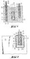
- a section of a carbon brush (10) is shown, in which a current-carrying wire (12) and a shut-off nipple (14) are arranged.
- the shut-off nipple (14) consists of insulating material and is spring-biased in the direction of the longitudinal axis (16) of the carbon brush (12), preferably by means of a helical spring (18).
- Both the stranded wire (12) and the shut-off nipple (14) are stamped into powdered-in metal powder (20) or (22).
- An insulating plate (24) on which the helical spring (18) is supported can also be arranged between the ramming powder (22) covering the shut-off nipple (14) and the end face facing it.
- a section (26) of a signaling wire (28) also runs inside the carbon brush (10), via which a signal is then triggered when the carbon brush (10) interacting with a commutator or slip ring (not shown) is worn to the extent that a Renewing is necessary, that is, before the carbon brush (10) is consumed to such an extent that the shut-off nipple (14) lifts the carbon brush (10) off the slip ring or the commutator.
- the signaling wire (28) is arranged in a blind hole (30) running essentially parallel to the longitudinal axis (16), the bottom surface (32) of which is flat, that is to say perpendicular or essentially perpendicular to the inner wall (34) of the blind hole (30). runs.
- coal dust creates a conductive connection between the carbon brush (10) and the signaling wire ( 28), d. H. to its conductive core (36), which is surrounded by an insulation jacket (38).
- the bottom surface (32) is covered with an insulating plate or plate (40), e.g. can consist of fiber material or hard paper.
- the free end (42) of the core (36) stands on the insulating plate (40).
- the insulation jacket (38) surrounding the core (36) can extend to the surface of the insulating plate or be stripped at a distance from it, as is illustrated in principle with reference to FIG. 1.
- the circumference of the section (26) is stamped in, namely by an insulating stamped powder, which is or may contain a thermoset.
- An insulating stamped powder which is or may contain a thermoset.
- a material sold under the name Minolite® can preferably be used.
- the cross section of the blind hole (30) is matched to the cross section of the core (36) of the section (26) of the signaling wire (28) surrounding the insulation jacket (38) and the thickness ( b) the insulating plate (40) chosen so that these and the distance (a) between the core (36) and the inner surface of the blind hole (30) are the same.
- the stamped powder (34) is covered on the outside with a coating (44) which extends from the surface of the carbon brush (10) to the outside of the insulation jacket (38).
- an insulation tape is unwound from a roll - above the blind hole opening - as is to be clarified in principle in FIG. 3 (46) moved in order to be punched out directly above the blind hole (30) by means of a punching tool (48) and to be pushed into the blind hole with the punching tool (48).
- a support (50) can be provided between the carbon brush (10) and the insulating tape material (46) for support.
- the signal wire (28) itself is also unwound from a roll and cut to the desired length. This takes place after the section (26) has been stamped into the blind hole (30). During the cutting, a voltage of z. B. 500 V, which is measured against the carbon brush (10). If the section (26) is insulated in the blind hole (30), no conductive connection between the cutting tool (48) and the carbon brush (10) may be determined. This measure results in a quality control which takes place simultaneously with the assembly of the carbon brush (10) with the signaling wire (28).
- the diameter of the blind hole (30) can e.g. 2.5 mm at a height of 5.3 mm.
- Typical dimensions for the cross section of the signaling wire (28) including the insulation jacket (38) are approximately 1.1 mm, the insulation jacket (38) having a thickness in the range between 0.125 and 0.25 mm.
- the thickness (b) of the insulation plate (40) and thus the distance (a) between the core (36) of the signaling wire (28) and the inner wall (34) of the blind hole (30) can be in the range of approximately 0.7 mm .
- insulation jacket (38) should consist of, for example, a polyester elastomer, Teflon or another temperature-resistant insulation.
- the paint finish (44) should be a two-component adhesive based on epoxy resin.
- FIG. 4 shows an embodiment of the teaching according to the invention to the extent that the signaling strand section (26) within the blind hole (30) is surrounded by a sleeve (50), preferably made of metal, such as a crimp sleeve.
- the crimp sleeve (50) ends at a distance from the free end (42) of the section (26) of the signaling wire (28).
- the outside of the sleeve should also be completely surrounded by ramming powder. This means that the upper edge (52) is covered by ramming powder, that is to say runs below the plane spanned by the surface of the carbon brush (10).
- the sleeve results on the one hand in a good fit of the signaling wire (28) in the blind hole (30) and on the other hand a higher mechanical strength is achieved, i. H. the pull-out strength is increased.
Landscapes
- Engineering & Computer Science (AREA)
- Manufacturing & Machinery (AREA)
- Motor Or Generator Current Collectors (AREA)
- Manufacturing Of Electrical Connectors (AREA)
- Ignition Installations For Internal Combustion Engines (AREA)
- Transmission And Conversion Of Sensor Element Output (AREA)
Claims (12)
- Balai en charbon (10) équipé d'un conducteur torsadé de contrôle (26, 28) pour signaler un degré défini d'usure du charbon, ce conducteur étant monté avec bourrage dans un évidement (30) creusé de préférence selon la direction longitudinale (16) du balai, tel qu'un trou borgne s'arrêtant à une certaine distance de fond (32) de l'évidement qui est garni d'un matériau isolant,
caractérisé en ce que
le matériau isolant est une couche isolante (40) rigide recouvrant le fond (32) de l'évidement (30), sous la forme d'une plaque ou d'une plaquette isolante. - Balai en charbon selon la revendication 1,
caractérisé en ce que
la plaque ou la plaquette isolante est faite d'un matériau fibreux ou de papier dur. - Balai en charbon selon la revendication 1 ou 2,
caractérisé en ce que
le conducteur torsadé de contrôle (26, 28) touche par son extrémité libre (42) la couche isolante (40) ou est posée sur elle. - Balai en charbon selon au moins une des revendications précédentes,
caractérisé en ce que
le conducteur torsadé de contrôle (26, 28) est entouré latéralement par un matériau isolant tel qu'une poudre de bourrage. - Balai en charbon selon au moins une des revendications précédentes,
caractérisé en ce que
l'épaisseur (b) de la couche isolante (40) est égale à la distance (a) existant entre la face externe de l'âme (36) du conducteur torsadé de contrôle (26, 28) et la paroi interne de l'évidement (30). - Balai en charbon selon au moins une des revendications précédentes,
caractérisé en ce que
la poudre de bourrage et le matériau de la couche isolante (40) ont des résistances spécifiques égales ou presque. - Balai en charbon selon au moins une des revendications précédentes,
caractérisé en ce que
entre le conducteur torsadé de contrôle (28) et la face supérieure du balai, une couche de vernis (44) recouvre la poudre de bourrage. - Balai en charbon selon au moins une des revendications précédentes,
caractérisé en ce que
la partie (26) du conducteur (28) est entourée par une douille (50), métallique de préférence, telle qu'une douille sertie dont la périphérie et les bords sont de préférence totalement entourés par la poudre de bourrage. - Procédé pour placer et fixer une partie d'un cordon indicateur à l'intérieur d'un balai de charbon, selon au moins la revendication 1, comportant les étapes suivantes :- alésage d'un trou borgne dont le fond est plan ou sensiblement plan,- introduction d'une couche isolante recouvrant le fond du trou borgne,- engagement du morceau de conducteur dans le trou borgne jusqu'à ce que son extrémité touche la couche isolante,- bourrage de matériau isolant autour du conducteur,- éventuellement, dépôt de vernis recouvrant la poudre de bourrage.
- Procédé selon la revendication 9,
caractérisé en ce que
le conducteur torsadé de contrôle, avant son engagement dans le trou borgne, est, au moins dans la partie qui se trouvera à l'intérieur du trou, entouré par une douille. - Procédé selon la revendication 9,
caractérisé en ce qu'
on amène au-dessus du trou borgne, en provenance d'un rouleau, un matériau isolant plan, dans lequel on estampe directement la plaque isolante au moyen d'un outil de découpage de manière à introduire ensuite directement, dans le trou borgne, cette plaque isolante par l'intermédiaire de l'outil ou d'une partie de celui-ci. - Procédé selon une quelconque des revendications 9 à 11,
caractérisé en ce que
le conducteur torsadé de contrôle est découpé à longueur par un outil de coupe et qu'une tension est établie entre cet outil et le balai en charbon pour contrôler que le conducteur est bien isolé, dans la position qu'il occupe à l'intérieur du trou.
Applications Claiming Priority (2)
| Application Number | Priority Date | Filing Date | Title |
|---|---|---|---|
| DE4315622A DE4315622C2 (de) | 1993-05-11 | 1993-05-11 | Kohlebürste sowie Verfahren zum Anordnen und Befestigen einer Meldelitze in einer solchen |
| DE4315622 | 1993-05-11 |
Publications (2)
| Publication Number | Publication Date |
|---|---|
| EP0624937A1 EP0624937A1 (fr) | 1994-11-17 |
| EP0624937B1 true EP0624937B1 (fr) | 1996-10-30 |
Family
ID=6487754
Family Applications (1)
| Application Number | Title | Priority Date | Filing Date |
|---|---|---|---|
| EP94107254A Expired - Lifetime EP0624937B1 (fr) | 1993-05-11 | 1994-05-10 | Balai de charbon ainsi qu'un procédé pour arranger et fixer un conducteur torsade de contrÔle dans celui-ci |
Country Status (5)
| Country | Link |
|---|---|
| US (1) | US5488261A (fr) |
| EP (1) | EP0624937B1 (fr) |
| AT (1) | ATE144863T1 (fr) |
| DE (2) | DE4315622C2 (fr) |
| ES (1) | ES2093472T3 (fr) |
Cited By (2)
| Publication number | Priority date | Publication date | Assignee | Title |
|---|---|---|---|---|
| DE102012209216A1 (de) | 2012-05-31 | 2013-12-05 | Schunk Wien Gesellschaft M.B.H. | Kohlebürste mit isolierendem Stampfpulver |
| DE102012209222A1 (de) * | 2012-05-31 | 2013-12-05 | Schunk Kohlenstofftechnik Gmbh | Kohlebürste mit Zentrierhülse |
Families Citing this family (11)
| Publication number | Priority date | Publication date | Assignee | Title |
|---|---|---|---|---|
| US5941370A (en) | 1996-09-10 | 1999-08-24 | Nichols; Bruce W. | Electrical contact wear |
| US5870026A (en) * | 1997-07-15 | 1999-02-09 | The Morgan Crucible Company Plc | Brush wear indicator |
| DE102006033231A1 (de) * | 2006-07-18 | 2008-01-24 | Siemens Ag | Einrichtung zum Anschluss eines zum Einsatz in einem Kraftstoffbehälter insbesondere eines Kraftfahrzeuges vorgesehenen Elektromotors |
| US8618943B2 (en) | 2007-05-24 | 2013-12-31 | Cutsforth, Inc. | Brush holder assembly monitoring apparatus, assembly, system and method |
| US7705744B2 (en) * | 2007-05-24 | 2010-04-27 | Cutsforth Products, Inc. | Monitoring systems and methods for monitoring the condition of one or more components of an electrical device |
| AU2007242948B2 (en) * | 2007-12-13 | 2010-04-01 | Hoffmann & Co Elektrokohle Ag | Carbon brush with connecting cable |
| DE102014202556C5 (de) * | 2014-02-12 | 2019-07-18 | Schunk Carbon Technology Gmbh | Kohlebürstenanordnung |
| CA2985094C (fr) | 2015-06-01 | 2022-03-22 | Cutsforth, Inc. | Surveillance de l'usure et des vibrations d'un balai |
| CA3008957C (fr) | 2016-01-11 | 2020-07-14 | Cutsforth, Inc. | Systeme de controle destine a un appareil de mise a la terre |
| CA3114764A1 (fr) | 2018-10-04 | 2020-04-09 | Cutsforth, Inc. | Systeme et procede de surveillance de l'etat d'un ou de plusieurs composants d'une machine electrique |
| CN113243063B (zh) | 2018-10-04 | 2023-11-07 | 科茨福斯有限公司 | 用于监控电机的一个或多个元件的状态的系统和方法 |
Family Cites Families (16)
| Publication number | Priority date | Publication date | Assignee | Title |
|---|---|---|---|---|
| US1188635A (en) * | 1914-05-07 | 1916-06-27 | American Carbon & Battery Co | Carbon-brush connection. |
| US1441640A (en) * | 1922-03-28 | 1923-01-09 | Union Carbide & Carbon Res Lab | Shunt connection |
| DE590677C (de) * | 1930-07-16 | 1934-01-08 | Siemens Planiawerke Akt Ges Fu | Verfahren zum Befestigen von Kupferlitzen in Metallkohlebuersten durch Einfuehren des mit einem Zinnknoten versehenen Endes der Kupferlitze in eine in der Kohle befindliche Bohrung und durch Ausfuellen dieser Bohrung |
| US2199532A (en) * | 1938-10-18 | 1940-05-07 | Arthur B Weeks | Shunt wire fastener |
| DE1739567U (de) * | 1955-04-27 | 1957-02-14 | Schunk & Ebe Gmbh | Kohlebuerste. |
| RO54721A2 (fr) * | 1970-07-21 | 1973-08-20 | ||
| FR2223858A1 (en) * | 1973-03-26 | 1974-10-25 | Salev | Electrical machine imbalance detection cct. - gives alarm or disconnects supply to prevent slipring damage |
| DE2804547A1 (de) * | 1978-02-03 | 1979-08-09 | Licentia Gmbh | Kohlebuerste fuer kollektormotoren |
| DE7920943U1 (de) * | 1979-07-21 | 1979-11-22 | Rekofa Wenzel Gmbh & Co Kg, 5483 Bad Neuenahr-Ahrweiler | Kohlebürste mit Abschaltvorrichtung |
| US4344072A (en) * | 1979-12-10 | 1982-08-10 | Harper Jr Harold L | Worn brush indicator |
| US4333095A (en) * | 1980-02-19 | 1982-06-01 | Reliance Electric Company | Brush wear indicator |
| US4536670A (en) * | 1981-12-14 | 1985-08-20 | Morganite Incorporated | Electrical brushes with wear sensors |
| US4636778A (en) * | 1983-10-03 | 1987-01-13 | Reliance Electric Company | Brush wear monitor |
| DE8433023U1 (de) * | 1984-11-10 | 1985-02-07 | Deutsche Carbone Ag, 6000 Frankfurt | Elektrische kohlebuerste mit meldekontakt |
| FR2592744B1 (fr) * | 1986-01-06 | 1988-10-07 | Ferraz | Dispositif pour la detection du seuil d'usure des contacts electriques du type a frottement |
| DE4111206A1 (de) * | 1991-04-06 | 1992-10-08 | Schunk Kohlenstofftechnik Gmbh | Kohlebuerste |
-
1993
- 1993-05-11 DE DE4315622A patent/DE4315622C2/de not_active Expired - Fee Related
-
1994
- 1994-05-10 AT AT94107254T patent/ATE144863T1/de not_active IP Right Cessation
- 1994-05-10 EP EP94107254A patent/EP0624937B1/fr not_active Expired - Lifetime
- 1994-05-10 DE DE59400929T patent/DE59400929D1/de not_active Expired - Fee Related
- 1994-05-10 ES ES94107254T patent/ES2093472T3/es not_active Expired - Lifetime
- 1994-05-11 US US08/241,363 patent/US5488261A/en not_active Expired - Fee Related
Cited By (3)
| Publication number | Priority date | Publication date | Assignee | Title |
|---|---|---|---|---|
| DE102012209216A1 (de) | 2012-05-31 | 2013-12-05 | Schunk Wien Gesellschaft M.B.H. | Kohlebürste mit isolierendem Stampfpulver |
| DE102012209222A1 (de) * | 2012-05-31 | 2013-12-05 | Schunk Kohlenstofftechnik Gmbh | Kohlebürste mit Zentrierhülse |
| WO2013178791A1 (fr) | 2012-05-31 | 2013-12-05 | Schunk Wien Gesellschaft M.B.H. | Balai de charbon doté de poudre isolante compactée |
Also Published As
| Publication number | Publication date |
|---|---|
| ES2093472T3 (es) | 1996-12-16 |
| ATE144863T1 (de) | 1996-11-15 |
| DE4315622C2 (de) | 1997-01-16 |
| US5488261A (en) | 1996-01-30 |
| DE59400929D1 (de) | 1996-12-05 |
| DE4315622A1 (de) | 1994-11-17 |
| EP0624937A1 (fr) | 1994-11-17 |
Similar Documents
| Publication | Publication Date | Title |
|---|---|---|
| EP0624937B1 (fr) | Balai de charbon ainsi qu'un procédé pour arranger et fixer un conducteur torsade de contrÔle dans celui-ci | |
| DE3787665T2 (de) | Verbindungseinrichtung für eine Übertragungsleitung, die zwei sich relativ zueinander bewegende Teile verbindet. | |
| DE60003742T2 (de) | Kabelstecker in welchem zwei Kontakte einen Drahtkern eines Kabels zwischen sich befestigen | |
| DE102020204947B4 (de) | Mit Anschlussklemme versehene Litze | |
| DE19528552B4 (de) | Koaxialer Verbinder für ein HF-Kabel | |
| DE19934967C2 (de) | Wasserdichter Verbinder | |
| DE4120527C2 (de) | Verschleiß-Sensor für Bremsklötze von Fahrzeugen | |
| DE19922139B4 (de) | Verfahren zur Montage eines Flachkabels an einem Stecker, Stecker für ein Flachkabel und Bauteil zum Erregen von Ultraschallschwingungen zur Verwendung bei diesem Verfahren | |
| EP1683235B1 (fr) | Connexion entre un câble coaxial et un connecteur et procédé de réalisation | |
| DE2835400A1 (de) | Leitungskupplung zum durchverbinden von zwei elektrischen leitungen | |
| EP0585591B1 (fr) | Balai en charbon | |
| DE2346567C3 (de) | Vorgefertigter Silikon-Kautschuk-Kabelendverschluß für kunststoffisolierte Starkstromkabel | |
| EP0512234B1 (fr) | Balai en charbon | |
| EP0272470B1 (fr) | Fiche électrique et procédé pour sa fabrication | |
| DE19525801C2 (de) | Vorrichtung zum elektrisch leitenden Verbinden von zwei elektrischen Leitungen | |
| EP0412123B1 (fr) | Semelle pour collecteur et procede de fabrication | |
| DE9307124U1 (de) | Kohlebürste | |
| DE29912812U1 (de) | Stecker-Schutzvorrichtung | |
| EP0696080A1 (fr) | Procédé de raccordement électrique de deux câbles électriques | |
| DE4017725C2 (fr) | ||
| EP0718924A2 (fr) | Procédé de fixation d'un câble électrique atténuant l'effort de tension | |
| DE8707304U1 (de) | Stecker | |
| DE3719210C2 (de) | Verfahren zur Herstellung eines Kupplungsteils eines elektrischen Steckverbinders | |
| DE19507028C2 (de) | Induktiver Drehzahlfühler | |
| DE9211524U1 (de) | Kohlebürste |
Legal Events
| Date | Code | Title | Description |
|---|---|---|---|
| PUAI | Public reference made under article 153(3) epc to a published international application that has entered the european phase |
Free format text: ORIGINAL CODE: 0009012 |
|
| AK | Designated contracting states |
Kind code of ref document: A1 Designated state(s): AT BE CH DE DK ES FR GB GR IE IT LI LU MC NL PT SE |
|
| 17P | Request for examination filed |
Effective date: 19941103 |
|
| RBV | Designated contracting states (corrected) |
Designated state(s): AT BE CH DE DK ES FR GB IT LI LU NL PT SE |
|
| 17Q | First examination report despatched |
Effective date: 19950708 |
|
| GRAG | Despatch of communication of intention to grant |
Free format text: ORIGINAL CODE: EPIDOS AGRA |
|
| GRAH | Despatch of communication of intention to grant a patent |
Free format text: ORIGINAL CODE: EPIDOS IGRA |
|
| GRAH | Despatch of communication of intention to grant a patent |
Free format text: ORIGINAL CODE: EPIDOS IGRA |
|
| GRAA | (expected) grant |
Free format text: ORIGINAL CODE: 0009210 |
|
| AK | Designated contracting states |
Kind code of ref document: B1 Designated state(s): AT BE CH DE DK ES FR GB IT LI LU NL PT SE |
|
| PG25 | Lapsed in a contracting state [announced via postgrant information from national office to epo] |
Ref country code: DK Effective date: 19961030 |
|
| REF | Corresponds to: |
Ref document number: 144863 Country of ref document: AT Date of ref document: 19961115 Kind code of ref document: T |
|
| REG | Reference to a national code |
Ref country code: CH Ref legal event code: NV Representative=s name: PATENTANWALTSBUREAU BOSSHARD UND LUCHS |
|
| REF | Corresponds to: |
Ref document number: 59400929 Country of ref document: DE Date of ref document: 19961205 |
|
| REG | Reference to a national code |
Ref country code: ES Ref legal event code: FG2A Ref document number: 2093472 Country of ref document: ES Kind code of ref document: T3 |
|
| ITF | It: translation for a ep patent filed | ||
| GBT | Gb: translation of ep patent filed (gb section 77(6)(a)/1977) |
Effective date: 19961129 |
|
| ET | Fr: translation filed | ||
| PG25 | Lapsed in a contracting state [announced via postgrant information from national office to epo] |
Ref country code: LU Free format text: LAPSE BECAUSE OF NON-PAYMENT OF DUE FEES Effective date: 19970531 Ref country code: BE Effective date: 19970531 |
|
| PLBE | No opposition filed within time limit |
Free format text: ORIGINAL CODE: 0009261 |
|
| STAA | Information on the status of an ep patent application or granted ep patent |
Free format text: STATUS: NO OPPOSITION FILED WITHIN TIME LIMIT |
|
| 26N | No opposition filed | ||
| BERE | Be: lapsed |
Owner name: SCHUNK KOHLENSTOFFTECHNIK G.M.B.H. Effective date: 19970531 |
|
| PGFP | Annual fee paid to national office [announced via postgrant information from national office to epo] |
Ref country code: PT Payment date: 19980430 Year of fee payment: 5 |
|
| PGFP | Annual fee paid to national office [announced via postgrant information from national office to epo] |
Ref country code: SE Payment date: 19980518 Year of fee payment: 5 |
|
| PGFP | Annual fee paid to national office [announced via postgrant information from national office to epo] |
Ref country code: ES Payment date: 19980528 Year of fee payment: 5 |
|
| PGFP | Annual fee paid to national office [announced via postgrant information from national office to epo] |
Ref country code: NL Payment date: 19980531 Year of fee payment: 5 |
|
| PG25 | Lapsed in a contracting state [announced via postgrant information from national office to epo] |
Ref country code: SE Free format text: LAPSE BECAUSE OF NON-PAYMENT OF DUE FEES Effective date: 19990511 Ref country code: ES Free format text: LAPSE BECAUSE OF NON-PAYMENT OF DUE FEES Effective date: 19990511 |
|
| PG25 | Lapsed in a contracting state [announced via postgrant information from national office to epo] |
Ref country code: PT Free format text: LAPSE BECAUSE OF NON-PAYMENT OF DUE FEES Effective date: 19991130 |
|
| PG25 | Lapsed in a contracting state [announced via postgrant information from national office to epo] |
Ref country code: NL Free format text: LAPSE BECAUSE OF NON-PAYMENT OF DUE FEES Effective date: 19991201 |
|
| EUG | Se: european patent has lapsed |
Ref document number: 94107254.8 |
|
| NLV4 | Nl: lapsed or anulled due to non-payment of the annual fee |
Effective date: 19991201 |
|
| REG | Reference to a national code |
Ref country code: PT Ref legal event code: MM4A Free format text: LAPSE DUE TO NON-PAYMENT OF FEES Effective date: 19991130 |
|
| REG | Reference to a national code |
Ref country code: ES Ref legal event code: FD2A Effective date: 20010503 |
|
| REG | Reference to a national code |
Ref country code: GB Ref legal event code: IF02 |
|
| PGFP | Annual fee paid to national office [announced via postgrant information from national office to epo] |
Ref country code: AT Payment date: 20070523 Year of fee payment: 14 |
|
| PGFP | Annual fee paid to national office [announced via postgrant information from national office to epo] |
Ref country code: DE Payment date: 20070526 Year of fee payment: 14 |
|
| PGFP | Annual fee paid to national office [announced via postgrant information from national office to epo] |
Ref country code: GB Payment date: 20070509 Year of fee payment: 14 Ref country code: CH Payment date: 20070719 Year of fee payment: 14 |
|
| PGFP | Annual fee paid to national office [announced via postgrant information from national office to epo] |
Ref country code: IT Payment date: 20070509 Year of fee payment: 14 |
|
| PGFP | Annual fee paid to national office [announced via postgrant information from national office to epo] |
Ref country code: FR Payment date: 20070529 Year of fee payment: 14 |
|
| REG | Reference to a national code |
Ref country code: CH Ref legal event code: PL |
|
| GBPC | Gb: european patent ceased through non-payment of renewal fee |
Effective date: 20080510 |
|
| PG25 | Lapsed in a contracting state [announced via postgrant information from national office to epo] |
Ref country code: LI Free format text: LAPSE BECAUSE OF NON-PAYMENT OF DUE FEES Effective date: 20080531 Ref country code: CH Free format text: LAPSE BECAUSE OF NON-PAYMENT OF DUE FEES Effective date: 20080531 |
|
| PG25 | Lapsed in a contracting state [announced via postgrant information from national office to epo] |
Ref country code: AT Free format text: LAPSE BECAUSE OF NON-PAYMENT OF DUE FEES Effective date: 20080510 |
|
| REG | Reference to a national code |
Ref country code: FR Ref legal event code: ST Effective date: 20090119 |
|
| PG25 | Lapsed in a contracting state [announced via postgrant information from national office to epo] |
Ref country code: FR Free format text: LAPSE BECAUSE OF NON-PAYMENT OF DUE FEES Effective date: 20080602 Ref country code: DE Free format text: LAPSE BECAUSE OF NON-PAYMENT OF DUE FEES Effective date: 20081202 |
|
| PG25 | Lapsed in a contracting state [announced via postgrant information from national office to epo] |
Ref country code: GB Free format text: LAPSE BECAUSE OF NON-PAYMENT OF DUE FEES Effective date: 20080510 |
|
| PG25 | Lapsed in a contracting state [announced via postgrant information from national office to epo] |
Ref country code: IT Free format text: LAPSE BECAUSE OF NON-PAYMENT OF DUE FEES Effective date: 20080510 |