EP0625470B1 - Müllbehälter mit einer Pressvorrichtung - Google Patents
Müllbehälter mit einer Pressvorrichtung Download PDFInfo
- Publication number
- EP0625470B1 EP0625470B1 EP93118844A EP93118844A EP0625470B1 EP 0625470 B1 EP0625470 B1 EP 0625470B1 EP 93118844 A EP93118844 A EP 93118844A EP 93118844 A EP93118844 A EP 93118844A EP 0625470 B1 EP0625470 B1 EP 0625470B1
- Authority
- EP
- European Patent Office
- Prior art keywords
- pressing plate
- container
- individual container
- individual
- manual pressing
- Prior art date
- Legal status (The legal status is an assumption and is not a legal conclusion. Google has not performed a legal analysis and makes no representation as to the accuracy of the status listed.)
- Expired - Lifetime
Links
- 238000005056 compaction Methods 0.000 title description 2
- 238000003825 pressing Methods 0.000 claims abstract description 36
- 238000007789 sealing Methods 0.000 claims abstract description 6
- 239000002699 waste material Substances 0.000 claims description 14
- NJPPVKZQTLUDBO-UHFFFAOYSA-N novaluron Chemical compound C1=C(Cl)C(OC(F)(F)C(OC(F)(F)F)F)=CC=C1NC(=O)NC(=O)C1=C(F)C=CC=C1F NJPPVKZQTLUDBO-UHFFFAOYSA-N 0.000 claims 2
- 239000010813 municipal solid waste Substances 0.000 description 9
- 238000000034 method Methods 0.000 description 4
- 238000010276 construction Methods 0.000 description 2
- 238000011161 development Methods 0.000 description 2
- 230000018109 developmental process Effects 0.000 description 2
- 239000010791 domestic waste Substances 0.000 description 2
- 238000004519 manufacturing process Methods 0.000 description 2
- 238000003860 storage Methods 0.000 description 2
- 238000004140 cleaning Methods 0.000 description 1
- 238000009826 distribution Methods 0.000 description 1
- 230000000694 effects Effects 0.000 description 1
- 239000000463 material Substances 0.000 description 1
- 239000002184 metal Substances 0.000 description 1
- 210000003205 muscle Anatomy 0.000 description 1
- 238000005192 partition Methods 0.000 description 1
- 239000003566 sealing material Substances 0.000 description 1
Images



Classifications
-
- B—PERFORMING OPERATIONS; TRANSPORTING
- B30—PRESSES
- B30B—PRESSES IN GENERAL
- B30B9/00—Presses specially adapted for particular purposes
- B30B9/30—Presses specially adapted for particular purposes for baling; Compression boxes therefor
- B30B9/3082—Presses specially adapted for particular purposes for baling; Compression boxes therefor with compression means other than rams performing a rectilinear movement
-
- B—PERFORMING OPERATIONS; TRANSPORTING
- B30—PRESSES
- B30B—PRESSES IN GENERAL
- B30B9/00—Presses specially adapted for particular purposes
- B30B9/30—Presses specially adapted for particular purposes for baling; Compression boxes therefor
- B30B9/305—Drive arrangements for the press ram
- B30B9/3053—Hand- or foot-operated presses
-
- B—PERFORMING OPERATIONS; TRANSPORTING
- B65—CONVEYING; PACKING; STORING; HANDLING THIN OR FILAMENTARY MATERIAL
- B65F—GATHERING OR REMOVAL OF DOMESTIC OR LIKE REFUSE
- B65F1/00—Refuse receptacles; Accessories therefor
- B65F1/0033—Refuse receptacles; Accessories therefor specially adapted for segregated refuse collecting, e.g. receptacles with several compartments; Combination of receptacles
- B65F1/0053—Combination of several receptacles
- B65F1/006—Rigid receptacles stored in an enclosure or forming part of it
-
- B—PERFORMING OPERATIONS; TRANSPORTING
- B65—CONVEYING; PACKING; STORING; HANDLING THIN OR FILAMENTARY MATERIAL
- B65F—GATHERING OR REMOVAL OF DOMESTIC OR LIKE REFUSE
- B65F1/00—Refuse receptacles; Accessories therefor
- B65F1/14—Other constructional features; Accessories
- B65F1/1405—Compressing means incorporated in, or specially adapted for, refuse receptacles
-
- B—PERFORMING OPERATIONS; TRANSPORTING
- B65—CONVEYING; PACKING; STORING; HANDLING THIN OR FILAMENTARY MATERIAL
- B65F—GATHERING OR REMOVAL OF DOMESTIC OR LIKE REFUSE
- B65F1/00—Refuse receptacles; Accessories therefor
- B65F1/14—Other constructional features; Accessories
- B65F1/1426—Housings, cabinets or enclosures for refuse receptacles
- B65F1/1436—Housings, cabinets or enclosures for refuse receptacles having a waste receptacle withdrawn upon opening of the enclosure
-
- B—PERFORMING OPERATIONS; TRANSPORTING
- B65—CONVEYING; PACKING; STORING; HANDLING THIN OR FILAMENTARY MATERIAL
- B65F—GATHERING OR REMOVAL OF DOMESTIC OR LIKE REFUSE
- B65F1/00—Refuse receptacles; Accessories therefor
- B65F1/14—Other constructional features; Accessories
- B65F1/16—Lids or covers
- B65F1/1623—Lids or covers with means for assisting the opening or closing thereof, e.g. springs
- B65F1/163—Pedal-operated lids
-
- Y—GENERAL TAGGING OF NEW TECHNOLOGICAL DEVELOPMENTS; GENERAL TAGGING OF CROSS-SECTIONAL TECHNOLOGIES SPANNING OVER SEVERAL SECTIONS OF THE IPC; TECHNICAL SUBJECTS COVERED BY FORMER USPC CROSS-REFERENCE ART COLLECTIONS [XRACs] AND DIGESTS
- Y10—TECHNICAL SUBJECTS COVERED BY FORMER USPC
- Y10S—TECHNICAL SUBJECTS COVERED BY FORMER USPC CROSS-REFERENCE ART COLLECTIONS [XRACs] AND DIGESTS
- Y10S220/00—Receptacles
- Y10S220/908—Trash container
- Y10S220/909—Segregated
Definitions
- the present invention relates to a refuse container system according to the preamble of claim 1.
- DE-U-7 813 581 provides as a stand-alone device a compressor plate which has a handle on the back. With it, the plate is to be pressed into the household waste container without soiling your hand or clothing, which is only reasonably possible with a higher filling level and then requires a lot of physical strength.
- a push lever mechanism can be folded up to the height of a lifting cylinder, with which a pressing plate can be extended, which allows greater forces to be exerted.
- a pressing plate can be extended, which allows greater forces to be exerted.
- the relatively heavy mechanics unloads quite high. This also applies to other waste presses, for example as described in DE-A-2 419 369. All of these devices require oversized stable containers because of the sometimes very high pressure forces.
- DE-A-2 446 894 goes into a niche, a box or the like. tiltable and removable garbage container emerges, over which sits a compactor with two motor-driven pairs of press rollers, the lower nip e.g. throws squeezed cans into the adjacent container opening. Often, however, there is not as great a height of the receiving box as required by the press unit, which is also expensive to drive.
- the invention aims to create an improved waste container system, which is particularly suitable in the living area with the separability of different waste for their compressed intermediate collection and simple disposal.
- the handling should be foolproof as far as possible, including waste compaction and emptying the containers, require little effort and be as hygienic as possible.
- the invention provides that the compressor can be moved and moved under the cover is formed in a front end position in the pre-tilted single container swiveling hand press plate. This arrangement is extremely simple and convenient to use. Because motor drives are not provided, the cost of purchase is greatly reduced, so that such a system can be purchased from any household thanks to inexpensive manufacture. Operation requires only moderate muscle strength, and the thrown-in waste can be compressed in relatively small portions.
- the individual container and hand press plate have a substantially rectangular basic shape and thus form a kind of narrow inserts.
- the hand press plate On both sides of the rear narrow side, the hand press plate has a sliding bearing according to claim 3, which also acts as a rotary bearing in the front end position.
- the hand press plate has guided on side rails sliding grooves with inner outlet ends, which leave the rails in the front end position, whereby the downward pivoting movement of the hand press plate is released around the sliding bearing.
- the sliding bearings of the hand press plate are expediently guided laterally below the cover by parallel strips, rails or the like.
- Claim 6 provides that the sliding bearing of sliding heads are formed, which protrude on both sides of the hand press plate, for example, from a rod located on the rear narrow side. It can be seen that the clear structure is very inexpensive to implement.
- the hand press plate on its underside has an inward / under protruding pressing body, which according to claim 8 can be formed on the top as a trough with a grip strip which is accessible from above / outside in the moving hand press plate and thus serves as a pressing surface and lifting handle can.
- the pressing body is resilient inward / downward and / or provided with a stop.
- the elastic design ensures a force or pressure distribution during the pressing process, so that edge areas in the individual container are also compacted.
- the stop can serve as a carrier in that, according to claim 10, the upper rear edge of the individual container takes the hand press plate with it when it tilts forward.
- the pressing body can carry or form the stop on the back. It can be seen that the mere opening of the individual container also moves the hand press plate forward, which can then be pulled out further by hand and pivoted downwards in order to carry out the pressing process.
- the individual container is supported with a shoulder located at the front on the bottom on a rib of a base serving as a tilting bearing in the receiving box.
- a front plate of the individual container has a sealing stop at the top, which in the container rest position at the front edge the cover comes into contact. This ensures an odor trap without the opening and closing of the waste container being somehow difficult.
- the individual container is optionally tiltable by means of a foot pressure bar or a handle and / or can be removed by means of a handle. This ensures the simplest operating options.
- the system is characterized according to claim 15 in that the box is designed to hold at least two battery-like individual containers arranged side by side.
- a triple or quad battery is particularly advantageous for waste sorting. Multiple combinations can also be clearly implemented in this way.
- the box preferably has a pivot bearing for the cover at the top of the rear wall, so that all the individual containers are visible and accessible from above.
- the cover can be cleaned particularly easily in this way. Furthermore, this structure allows, if greater effort is not an obstacle, the placement of motor-driven waste crushing and pressing devices.
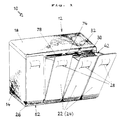
- a garbage container system is designated by a total of 10 in FIG. 1. It has a receiving box 12 with side walls 14, a rear wall 16 (FIGS. 2a to 2e) and a cover 18 designed as a cover plate.
- the receiving box 12 encloses a storage space 20 for a number of individual containers 22 which close off the box 12 with its front plate 24 .
- FIGS. 2a to 2e Beneath the cover 18 is a hand press plate 30, which has a binding recess 32 in the front area and is supported with sliding bearings 34 in the rear area within a side guide 40.
- the sliding bearings 34 can be attached to a rod 36 on the rear narrow side of the hand press plate 30 in the form of sliding heads 38 (FIG. 4).
- Each individual container 22 has an opening 42 at the top for receiving waste with or without an inserted bag (not shown).
- a shoulder 44 and a cam 46 together define a channel which rides on a rib 54 of a base 52 of the receiving box 12. It can be seen that a simple tilting bearing is formed in this way, which immediately positions the removed container 22 when it is reinserted.
- the hand press plate 30 has sliding grooves 58 on both sides, the outlet ends 72 of which have a predetermined distance from the sliding bearings 34/38.
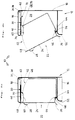
- this On the underside of the hand press plate 30, this has a pressing body 60 with a rear stop 70 which is carried along by the rear edge 68 of the individual container 22 as soon as it is tilted forward (FIG. 2b). This opens the opening 42 for throwing in waste. If this is to be compressed, the individual container 22 is moved further forward, be it by pressure on the baseboard 26 or by pulling on the handle 28. At the same time, the hand pressing plate 30 is pulled further forward (FIG. 2c), so that the sliding bearing 34 go forward from the rest position. In a front end position 50 (FIG. 2d) the outlet ends 72 have left the rails 40; Now the hand press plate on path 76 can be pivoted downward by pressing on the trough 32 in order to press the contents of the individual container 22.
- a grip bar 78 makes it easier to grip the hand press plate 30 in the region of the trough 32 and forms a lifting handle.
- each individual container 22 has a sealing stop 48 on the top of the front plate 24, which comes to rest on the front edge 74 of the cover 18. Suitable (not shown) sealing material can support the sealing effect at these points.
- FIG. 2e illustrates the handling of the garbage container system 10, in that the handling is shown to a certain extent in snapshots.
- a rest position generally designated I, corresponds to the illustration in FIG. 2a.
- position II (corresponding to FIG. 2c) is then shown, the The rear edge 68 of the individual container 22 has reached the stop 70 of the pressing body 60 and the hand pressing plate 30 has already advanced a little.
- position III the individual container 22 is fully tilted, the sliding bearings 34, 38 have reached their end positions 50 and the hand press plate 30 can therefore be pivoted into the interior of the container.
- the hand press plate 30 When the pressing process is finished, the hand press plate 30 is lifted with the grip bar 78 and pushed back in a horizontal position on the slide guide 40/58, the stop 70 already taking the rear edge 68 of the individual container 22 with it. The container 22 is pivoted back into the rest position I with the handle 28.
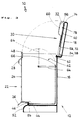
- FIG. 3 A pivot bearing 62 for the cover 18 can be seen here, which is drawn here in the folded-up position.
- the receiving box 12 is therefore freely accessible from above and can be viewed in full.
- Each individual container 22 can be provided with a handle 64 which, when not in use, can be pivoted backwards as drawn with solid lines, but can also be pivoted upwards (dashed lines) and forwards, engaging in a recess 66.
- a handle 64 can hold an insert bag (not shown).
- FIG. 4 shows the system 10 again with different positions of the four individual containers 22 used here.
- the rest position (corresponding to I in FIG. 2c) is shown on the left.
- the subsequent individual container 22 is already partially tilted, but the hand press plate 30 is still in its rest position.
- the intermediate position (II, Fig. 2c) is reached, in which the hand press plate 30 is already extended a bit and the individual container 22 is completely tilted.
- the working position III is shown on the far right, in which the extended hand press plate 30 can be pressed downward, as schematically indicated by a dash-dotted arrow.
- a preferred garbage container system 10 has a receiving box 12 with a storage space 20 for individual containers 22 which can be tilted and removed to the front.
- a hand press plate 30 which can be pulled forward in sliding guides 40, 58 and can be swiveled down in the end position 50 and which has a push / pivot bearing 34 on both sides at the rear.
- a pressing body 60 projects inward / downward from the hand pressing plate 30, the upper side of which forms a depression 32 accessible from above / outside and has a grip strip 78.
- a stop 70 on the pressing body 60 is carried along by the upper rear edge 68 of the individual container 22 when it is tilted forward.
- the individual container 22 is supported with a shoulder 42 located at the front on the bottom as Rib 54 serving a tilt bearing from a base 52 in the receiving box 12 and can optionally be tilted by means of a foot pressure bar 26 or a handle 28 and / or can be removed by means of a carrying handle 64.
- a sealing stop 48 on top of the front plate 24 comes to rest in the container rest position on the front edge 74 of the cover 18.
- the box 12 accommodates at least two individual containers 22 arranged next to one another in the manner of a battery.
- a pivot bearing for the cover 18 can be provided on the rear wall at the top.
Landscapes
- Engineering & Computer Science (AREA)
- Mechanical Engineering (AREA)
- Refuse Receptacles (AREA)
- Refuse Collection And Transfer (AREA)
- Processing Of Solid Wastes (AREA)
- Drying Of Solid Materials (AREA)
Applications Claiming Priority (2)
| Application Number | Priority Date | Filing Date | Title |
|---|---|---|---|
| DE9307748U | 1993-05-21 | ||
| DE9307748U DE9307748U1 (de) | 1993-05-21 | 1993-05-21 | Müllbehältersystem |
Publications (2)
| Publication Number | Publication Date |
|---|---|
| EP0625470A1 EP0625470A1 (de) | 1994-11-23 |
| EP0625470B1 true EP0625470B1 (de) | 1995-04-19 |
Family
ID=6893587
Family Applications (1)
| Application Number | Title | Priority Date | Filing Date |
|---|---|---|---|
| EP93118844A Expired - Lifetime EP0625470B1 (de) | 1993-05-21 | 1993-11-24 | Müllbehälter mit einer Pressvorrichtung |
Country Status (7)
| Country | Link |
|---|---|
| US (1) | US5421252A (da) |
| EP (1) | EP0625470B1 (da) |
| AT (1) | ATE121364T1 (da) |
| CA (1) | CA2114181C (da) |
| DE (2) | DE9307748U1 (da) |
| DK (1) | DK0625470T3 (da) |
| ES (1) | ES2073945T3 (da) |
Families Citing this family (26)
| Publication number | Priority date | Publication date | Assignee | Title |
|---|---|---|---|---|
| DE9307748U1 (de) * | 1993-05-21 | 1993-07-29 | Reichel, Günter, 35232 Dautphetal | Müllbehältersystem |
| DE4424002C2 (de) * | 1994-07-07 | 1996-05-23 | Hammer Lit Gmbh | Wertstoffsammler |
| BE1012592A3 (fr) * | 1996-04-10 | 2001-01-09 | Amatucci Aldo | Poubelles ecologiques. |
| US5884556A (en) * | 1997-09-30 | 1999-03-23 | Koncept Kreations, Ltd. | Trash handling device |
| DE10019633A1 (de) * | 1999-04-19 | 2001-01-18 | Hermann Schwelling | Ballenpresse mit kippbarem Presskasten sowie Verfahren zur Betätigung selbiger |
| US6193091B1 (en) * | 1999-06-18 | 2001-02-27 | Wundale Holding S.A. | Recycling bin |
| DE10004057C2 (de) * | 2000-02-01 | 2002-06-20 | Hammer Lit Gmbh | Wertstoffsammler |
| FI5550U1 (fi) * | 2001-04-19 | 2002-10-17 | Bent Eriksen Handelsselskab Ap | Paperijätteiden tiivistämiseen tarkoitettu säiliö |
| US6694871B1 (en) * | 2001-05-03 | 2004-02-24 | Ips Balers, Inc. | Baler having pre-compression lid stops and method of operation |
| US6652047B1 (en) * | 2001-08-09 | 2003-11-25 | Peter C. Maguire, Jr. | Device for storing pills and indicating quantity of the pills to be taken at times specifically indicated thereon |
| US6962301B1 (en) * | 2004-06-14 | 2005-11-08 | Michilin Prosperity Co., Ltd. | Front-lifting wastebasket for paper shredder also served as garbage bin |
| US7195185B2 (en) * | 2004-11-02 | 2007-03-27 | Fellowes, Inc. | Shredder with separate waste opening |
| GB2420151A (en) * | 2004-11-10 | 2006-05-17 | Peter Clarke | Cradle hinge system |
| ES2439575T3 (es) * | 2005-10-24 | 2014-01-23 | Lg Electronics, Inc. | Deshumidificador |
| AU2005337686A1 (en) * | 2005-10-28 | 2007-05-03 | Sca Hygiene Products Ab | Waste bin having compacting means |
| PL2015796T3 (pl) * | 2006-05-09 | 2010-03-31 | Medela Holding Ag | Przenośny ssak medyczny do płynów ustrojowych |
| ITVI20080051A1 (it) * | 2008-02-29 | 2009-09-01 | E P M Europe Proget Marketing | Dispositivo portarifiuti con compattatore |
| GB2458926B (en) * | 2008-04-01 | 2010-03-03 | Peter Bernt Forbes | Compacting bin |
| WO2010042213A1 (en) | 2008-10-10 | 2010-04-15 | Estech, Llc | Solid waste compression loading and waste treatment apparatus and method |
| GB2469799A (en) * | 2009-04-27 | 2010-11-03 | Neil Morgan | Wheelie bin with five relatively pivotable compartments to separate waste |
| ITBS20110135A1 (it) * | 2011-09-29 | 2013-03-30 | Scalvenzi Societa Cooperativa | Dispositivo e assieme per la compattazione di rifiuti solidi |
| US9113706B1 (en) * | 2012-08-27 | 2015-08-25 | Janie H. Cannon | Moveable stackable recycling bin system |
| USD691804S1 (en) * | 2012-09-26 | 2013-10-22 | Wen-Tsan Wang | Storage box |
| USD708439S1 (en) * | 2013-01-15 | 2014-07-08 | Wen-Tsan Wang | Storage box |
| US9745128B2 (en) * | 2015-07-31 | 2017-08-29 | Robert Romano | Trash container |
| CN105383834A (zh) * | 2015-12-04 | 2016-03-09 | 鹤山市裕熙环卫设备实业有限公司 | 一种可旋转垃圾箱 |
Family Cites Families (16)
| Publication number | Priority date | Publication date | Assignee | Title |
|---|---|---|---|---|
| DE7813581U1 (de) * | 1978-10-26 | Gatzweiler, Winfried, 4300 Essen | Müllstaucher | |
| CA764207A (en) * | 1967-08-01 | B. Crafoord Carl-Gustaf | Device for compression of the contents of containers | |
| DE7737376U1 (de) * | 1978-09-21 | Acher, Heinz, 6360 Friedberg | Stampfvorrichtuhg zum Verdichten von Müll und Abfällen in Behältern und Säcken | |
| US2386929A (en) * | 1943-08-03 | 1945-10-16 | Kenneth L Brown | Trash and garbage receptacle |
| US2593455A (en) * | 1950-05-27 | 1952-04-22 | Herbert Pensig | Sanitary waste disposal bin |
| US2970533A (en) * | 1958-11-06 | 1961-02-07 | Steve R Allen | Trash basket |
| US3202346A (en) * | 1963-10-11 | 1965-08-24 | Philip F Jacobs | Receptacle |
| GB1078501A (en) * | 1964-10-07 | 1967-08-09 | Bonniefoeretagen Ab | A device for compression of the contents of a container |
| DE2419369A1 (de) * | 1974-04-22 | 1975-11-06 | Bosch Siemens Hausgeraete | Geraet zum zusammenpressen von sperrigem gut, insbesondere haushaltsmuell-verdichter |
| DE2446894A1 (de) * | 1974-10-01 | 1976-05-20 | Rolf Schauwecker | Muellbehaelter mit verdichter |
| DE8326524U1 (de) * | 1983-09-15 | 1983-11-10 | Kaminski, Traugott, 3008 Garbsen | Altrohstoffsammelbehaelter |
| DE8706920U1 (de) * | 1987-05-14 | 1987-07-02 | Gebrüder Schulte GmbH & Co KG, 5768 Sundern | Müllverdichter |
| DE4006067A1 (de) * | 1990-02-26 | 1991-08-29 | Anton Heninger | Behaelteranordnung zum sortieren und getrennten ansammeln von muell |
| DE4013107A1 (de) * | 1990-04-25 | 1991-10-31 | Andreas Benz Apparatebau Gmbh | Pressvorrichtung fuer muell |
| DE9209862U1 (de) * | 1992-07-17 | 1992-09-17 | Reuter, Rolf Dieter, 4044 Kaarst | Vorrichtung zum vorzugsweise getrennten Sammeln von Abfall |
| DE9307748U1 (de) * | 1993-05-21 | 1993-07-29 | Reichel, Günter, 35232 Dautphetal | Müllbehältersystem |
-
1993
- 1993-05-21 DE DE9307748U patent/DE9307748U1/de not_active Expired - Lifetime
- 1993-11-24 EP EP93118844A patent/EP0625470B1/de not_active Expired - Lifetime
- 1993-11-24 AT AT93118844T patent/ATE121364T1/de not_active IP Right Cessation
- 1993-11-24 ES ES93118844T patent/ES2073945T3/es not_active Expired - Lifetime
- 1993-11-24 DK DK93118844.5T patent/DK0625470T3/da active
- 1993-11-24 DE DE59300151T patent/DE59300151D1/de not_active Expired - Fee Related
-
1994
- 1994-01-25 CA CA002114181A patent/CA2114181C/en not_active Expired - Fee Related
- 1994-01-28 US US08/186,986 patent/US5421252A/en not_active Expired - Fee Related
Also Published As
| Publication number | Publication date |
|---|---|
| CA2114181A1 (en) | 1994-11-22 |
| ES2073945T3 (es) | 1995-08-16 |
| EP0625470A1 (de) | 1994-11-23 |
| DK0625470T3 (da) | 1995-09-18 |
| DE9307748U1 (de) | 1993-07-29 |
| DE59300151D1 (de) | 1995-05-24 |
| US5421252A (en) | 1995-06-06 |
| ATE121364T1 (de) | 1995-05-15 |
| CA2114181C (en) | 1999-02-23 |
Similar Documents
| Publication | Publication Date | Title |
|---|---|---|
| EP0625470A1 (de) | Müllbehälter mit einer Pressvorrichtung | |
| DE2558433C3 (de) | Müllsammei- und Transportsystem | |
| DE3614328C2 (de) | Schüttung an einem Müllfahrzeug und Müllbehälter für diese Schüttung | |
| DE3506586C1 (de) | Müllsammelfahrzeug | |
| DE2162189C3 (de) | Gerät zum Zusammendrücken von MOU | |
| DE4310841C2 (de) | Vorrichtung für getrenntes Sammeln unterschiedlicher Haushaltsabfälle | |
| DE4424002C2 (de) | Wertstoffsammler | |
| DE4142206A1 (de) | Eingabe kontrolleinrichtung fuer muellbehaelter | |
| DE4237143A1 (en) | Compactor for refuse in refuse skip - has swinging panel with flap which is retracted on up-stroke of panel | |
| DE2820276A1 (de) | Vorrichtung zum umladen von muell aus muellfahrzeugen in grossbehaelterfahrzeuge | |
| DE4321784A1 (de) | Müll-Sammelvorrichtung mit mindestens einer Einwurföffnung zum Entsorgen von Haushaltsmüll wie Kartonagen, Blechdosen, Plastikmaterial, Gläser, Flaschen, Kompostmüll o. dgl. | |
| DE10004057C2 (de) | Wertstoffsammler | |
| EP0105862A1 (de) | Müllpresse | |
| DE69400482T2 (de) | Vorrichtung und Verfahren zum getrennten Sammeln und Verdichten von Müll in einem Müllsammelfahrzeug | |
| DE3418829C2 (de) | Aschesammelbehälter | |
| DE2264777C3 (de) | Haushaltsmüllpresse mit herausschwenkbarer Beschickungsklappe | |
| DE69600944T2 (de) | Vorrichtung zum getrennten Sammeln von Müll | |
| DE19819864C1 (de) | Abfall- und Altstoff-Sammelschrank | |
| DE3639916C2 (da) | ||
| DE19543828C1 (de) | Küchenmaschinenanordnung mit Krümelschale | |
| EP0607975B1 (de) | Müllbehälterschrank | |
| DE4226978A1 (de) | Containerpresse | |
| AT397632B (de) | Presse | |
| AT405503B (de) | Abfallsammler, insbesondere für papierhandtücher | |
| DE2357467C3 (de) | Kehrmaschine |
Legal Events
| Date | Code | Title | Description |
|---|---|---|---|
| PUAI | Public reference made under article 153(3) epc to a published international application that has entered the european phase |
Free format text: ORIGINAL CODE: 0009012 |
|
| 17P | Request for examination filed |
Effective date: 19940624 |
|
| AK | Designated contracting states |
Kind code of ref document: A1 Designated state(s): AT BE CH DE DK ES FR GB GR IT LI NL SE |
|
| GRAA | (expected) grant |
Free format text: ORIGINAL CODE: 0009210 |
|
| AK | Designated contracting states |
Kind code of ref document: B1 Designated state(s): AT BE CH DE DK ES FR GB GR IT LI NL SE |
|
| REF | Corresponds to: |
Ref document number: 121364 Country of ref document: AT Date of ref document: 19950515 Kind code of ref document: T |
|
| REF | Corresponds to: |
Ref document number: 59300151 Country of ref document: DE Date of ref document: 19950524 |
|
| ET | Fr: translation filed | ||
| ITF | It: translation for a ep patent filed | ||
| REG | Reference to a national code |
Ref country code: ES Ref legal event code: FG2A Ref document number: 2073945 Country of ref document: ES Kind code of ref document: T3 |
|
| GBT | Gb: translation of ep patent filed (gb section 77(6)(a)/1977) |
Effective date: 19950726 |
|
| REG | Reference to a national code |
Ref country code: GR Ref legal event code: FG4A Free format text: 3016613 |
|
| REG | Reference to a national code |
Ref country code: DK Ref legal event code: T3 |
|
| PGFP | Annual fee paid to national office [announced via postgrant information from national office to epo] |
Ref country code: GR Payment date: 19951212 Year of fee payment: 3 |
|
| PLBE | No opposition filed within time limit |
Free format text: ORIGINAL CODE: 0009261 |
|
| STAA | Information on the status of an ep patent application or granted ep patent |
Free format text: STATUS: NO OPPOSITION FILED WITHIN TIME LIMIT |
|
| 26N | No opposition filed | ||
| PG25 | Lapsed in a contracting state [announced via postgrant information from national office to epo] |
Ref country code: GR Free format text: THE PATENT HAS BEEN ANNULLED BY A DECISION OF A NATIONAL AUTHORITY Effective date: 19970531 |
|
| REG | Reference to a national code |
Ref country code: GR Ref legal event code: MM2A Free format text: 3016613 |
|
| PGFP | Annual fee paid to national office [announced via postgrant information from national office to epo] |
Ref country code: SE Payment date: 19971117 Year of fee payment: 5 Ref country code: CH Payment date: 19971117 Year of fee payment: 5 |
|
| PGFP | Annual fee paid to national office [announced via postgrant information from national office to epo] |
Ref country code: BE Payment date: 19971121 Year of fee payment: 5 |
|
| PGFP | Annual fee paid to national office [announced via postgrant information from national office to epo] |
Ref country code: DK Payment date: 19971125 Year of fee payment: 5 |
|
| PGFP | Annual fee paid to national office [announced via postgrant information from national office to epo] |
Ref country code: NL Payment date: 19971130 Year of fee payment: 5 |
|
| PGFP | Annual fee paid to national office [announced via postgrant information from national office to epo] |
Ref country code: AT Payment date: 19981113 Year of fee payment: 6 |
|
| PG25 | Lapsed in a contracting state [announced via postgrant information from national office to epo] |
Ref country code: DK Free format text: LAPSE BECAUSE OF NON-PAYMENT OF DUE FEES Effective date: 19981124 |
|
| PG25 | Lapsed in a contracting state [announced via postgrant information from national office to epo] |
Ref country code: SE Free format text: LAPSE BECAUSE OF NON-PAYMENT OF DUE FEES Effective date: 19981125 |
|
| PG25 | Lapsed in a contracting state [announced via postgrant information from national office to epo] |
Ref country code: LI Free format text: LAPSE BECAUSE OF NON-PAYMENT OF DUE FEES Effective date: 19981130 Ref country code: CH Free format text: LAPSE BECAUSE OF NON-PAYMENT OF DUE FEES Effective date: 19981130 Ref country code: BE Free format text: LAPSE BECAUSE OF NON-PAYMENT OF DUE FEES Effective date: 19981130 |
|
| BERE | Be: lapsed |
Owner name: REICHEL GUNTER Effective date: 19981130 |
|
| PG25 | Lapsed in a contracting state [announced via postgrant information from national office to epo] |
Ref country code: NL Free format text: LAPSE BECAUSE OF NON-PAYMENT OF DUE FEES Effective date: 19990601 |
|
| REG | Reference to a national code |
Ref country code: CH Ref legal event code: PL |
|
| EUG | Se: european patent has lapsed |
Ref document number: 93118844.5 |
|
| NLV4 | Nl: lapsed or anulled due to non-payment of the annual fee |
Effective date: 19990601 |
|
| PG25 | Lapsed in a contracting state [announced via postgrant information from national office to epo] |
Ref country code: AT Free format text: LAPSE BECAUSE OF NON-PAYMENT OF DUE FEES Effective date: 19991124 |
|
| REG | Reference to a national code |
Ref country code: DK Ref legal event code: EBP |
|
| PGFP | Annual fee paid to national office [announced via postgrant information from national office to epo] |
Ref country code: FR Payment date: 20001110 Year of fee payment: 8 |
|
| PGFP | Annual fee paid to national office [announced via postgrant information from national office to epo] |
Ref country code: ES Payment date: 20001114 Year of fee payment: 8 |
|
| PGFP | Annual fee paid to national office [announced via postgrant information from national office to epo] |
Ref country code: GB Payment date: 20001115 Year of fee payment: 8 |
|
| PGFP | Annual fee paid to national office [announced via postgrant information from national office to epo] |
Ref country code: DE Payment date: 20011031 Year of fee payment: 9 |
|
| PG25 | Lapsed in a contracting state [announced via postgrant information from national office to epo] |
Ref country code: GB Free format text: LAPSE BECAUSE OF NON-PAYMENT OF DUE FEES Effective date: 20011124 |
|
| PG25 | Lapsed in a contracting state [announced via postgrant information from national office to epo] |
Ref country code: ES Free format text: LAPSE BECAUSE OF NON-PAYMENT OF DUE FEES Effective date: 20011125 |
|
| REG | Reference to a national code |
Ref country code: GB Ref legal event code: IF02 |
|
| GBPC | Gb: european patent ceased through non-payment of renewal fee |
Effective date: 20011124 |
|
| PG25 | Lapsed in a contracting state [announced via postgrant information from national office to epo] |
Ref country code: FR Free format text: LAPSE BECAUSE OF NON-PAYMENT OF DUE FEES Effective date: 20020730 |
|
| REG | Reference to a national code |
Ref country code: FR Ref legal event code: ST |
|
| REG | Reference to a national code |
Ref country code: FR Ref legal event code: ST |
|
| PG25 | Lapsed in a contracting state [announced via postgrant information from national office to epo] |
Ref country code: DE Free format text: LAPSE BECAUSE OF NON-PAYMENT OF DUE FEES Effective date: 20030603 |
|
| REG | Reference to a national code |
Ref country code: ES Ref legal event code: FD2A Effective date: 20021213 |
|
| PG25 | Lapsed in a contracting state [announced via postgrant information from national office to epo] |
Ref country code: IT Free format text: LAPSE BECAUSE OF NON-PAYMENT OF DUE FEES;WARNING: LAPSES OF ITALIAN PATENTS WITH EFFECTIVE DATE BEFORE 2007 MAY HAVE OCCURRED AT ANY TIME BEFORE 2007. THE CORRECT EFFECTIVE DATE MAY BE DIFFERENT FROM THE ONE RECORDED. Effective date: 20051124 |