EP0625480A2 - Harness collar - Google Patents
Harness collar Download PDFInfo
- Publication number
- EP0625480A2 EP0625480A2 EP94107795A EP94107795A EP0625480A2 EP 0625480 A2 EP0625480 A2 EP 0625480A2 EP 94107795 A EP94107795 A EP 94107795A EP 94107795 A EP94107795 A EP 94107795A EP 0625480 A2 EP0625480 A2 EP 0625480A2
- Authority
- EP
- European Patent Office
- Prior art keywords
- collar
- cushion
- support ring
- connecting devices
- collar according
- Prior art date
- Legal status (The legal status is an assumption and is not a legal conclusion. Google has not performed a legal analysis and makes no representation as to the accuracy of the status listed.)
- Withdrawn
Links
- 230000000087 stabilizing effect Effects 0.000 claims abstract description 19
- 208000007101 Muscle Cramp Diseases 0.000 claims abstract description 9
- 230000000452 restraining effect Effects 0.000 claims abstract description 6
- XEEYBQQBJWHFJM-UHFFFAOYSA-N Iron Chemical compound [Fe] XEEYBQQBJWHFJM-UHFFFAOYSA-N 0.000 claims description 14
- 239000002984 plastic foam Substances 0.000 claims description 8
- 229910052742 iron Inorganic materials 0.000 claims description 7
- 239000011324 bead Substances 0.000 claims description 5
- 230000006641 stabilisation Effects 0.000 claims description 5
- 238000011105 stabilization Methods 0.000 claims description 5
- 239000010985 leather Substances 0.000 description 2
- 239000000463 material Substances 0.000 description 2
- 239000002184 metal Substances 0.000 description 2
- 229910052751 metal Inorganic materials 0.000 description 2
- 238000004873 anchoring Methods 0.000 description 1
- 238000004519 manufacturing process Methods 0.000 description 1
- 239000010902 straw Substances 0.000 description 1
- 238000003466 welding Methods 0.000 description 1
Images
Classifications
-
- B—PERFORMING OPERATIONS; TRANSPORTING
- B68—SADDLERY; UPHOLSTERY
- B68B—HARNESS; DEVICES USED IN CONNECTION THEREWITH; WHIPS OR THE LIKE
- B68B3/00—Traction harnesses; Traction harnesses combined with devices referred to in group B68B1/00
- B68B3/04—Horse collars; Manufacturing same
Definitions
- the invention relates to a collar for connecting a horse to a vehicle according to the preamble of claim 1.
- Such a collar usually consists of an annular collar cushion, which is placed around the neck of the horse and on the corresponding connecting devices in the form of pulling cramps, retaining ring, etc., which accommodate the attachment of pulling straps, retaining straps and the like.
- an annular collar cushion which is placed around the neck of the horse and on the corresponding connecting devices in the form of pulling cramps, retaining ring, etc., which accommodate the attachment of pulling straps, retaining straps and the like.
- This metal Kummetbügel is usually subject to high alternating loads, because when the horse pulls the carriage, high tensile forces act on it via the pulling cramps, which are derived on the Kummetkissen. In contrast, high pressure or restraining forces then act on the bracket when, particularly when stopping or driving downhill, etc., the carriage pushing forward has to be braked.
- the invention is therefore based on the object of designing the collar of the generic type in order to eliminate the disadvantages described in such a way that it is able to withstand high alternating loads, while at the same time ensuring a safe, consistently good anchoring of the connecting devices on the collar.
- the kummet according to the invention is based on the essential idea of guiding the tensile and restraining forces acting on it into the interior of the kummet and having it act there on a separate holding structure in the form of a supporting or stabilizing structure, which in turn is anchored in the interior of the kummet.
- This has the advantage that the connecting devices, such as pulling cramps, retaining ring etc., are fixed immovably on the kummet cushion, so that the risk of unintentional opening or loosening of the kummet bow no longer exists.
- the support and stabilization frame is a support ring which is embedded in the interior of the collet cushion and on which the connecting devices, ie the pulling cramps, the retaining ring, etc., are fixed.
- This support ring is expediently tubular in cross-section, but any other suitable cross-sectional shape can also be used.
- the support ring is embedded in the plastic foam of the Kummetkissen and in this way safely in is anchored in its position. In this case, the support ring is then expediently rigidly connected to the connecting devices via webs.
- the supporting and stabilizing frame prefferably has a stabilizing bar which is embedded in a groove between the collar cushion and a bead adjoining it.
- This stabilizing bar is advantageously designed as a flat iron in cross section in order to have the necessary torsional rigidity due to its cross section.
- the stabilizing bar for example the flat iron
- the stabilizing bar is either itself embedded directly in the interior of the collar cushion or else, if inside the collar cushion a support ring is arranged, connected to this support ring.
- connection between the stabilizing bar and the support ring is expediently carried out by means of webs which are arranged at a distance from one another and ensure a rigid connection between the two mentioned parts of the support and stabilizing frame formed as a whole.
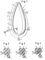
- the collar 1 shown has in the usual manner an annular cushion 2 which, when a horse is to be pulled, is to be placed around the horse's neck .
- the cushion 2 is filled with a customary suitable cushioning material 3, which consists of plastic foam in the illustrated embodiment.
- the connecting devices consist on the one hand of two pulling cramps 5 and, on the other hand, of a retaining ring 6, the two pulling cramps 5 being arranged on both sides of the collar 1 in the lower half thereof and serving to accommodate tension belts, while the retaining ring 6 is arranged at the lower end of collar 1 and to hold the - usually leather - pick-up or strap.
- connection devices 5, 6 are fixed on the collar 1 by means of a support and stabilization frame, which in the exemplary embodiment according to FIGS. 1 and 2 consists of a stabilization bracket 7 in the form of a flat iron.
- a support and stabilization frame which in the exemplary embodiment according to FIGS. 1 and 2 consists of a stabilization bracket 7 in the form of a flat iron.
- the stabilizing bar 7 in turn is anchored in the interior of the collar cushion 2, in such a way that it is immovably embedded in a groove 8 which is formed between the collar cushion 2 and the bead 4.
- the embedding of the flat iron 7 in this groove 8 is preferably carried out simultaneously with the production of the Kummetkissen 2 formed from plastic foam 3, so that this results in an intimate connection between the plastic foam 3 and the flat iron 7.
- the stabilizing bracket 7, which is likewise designed as a flat iron, is not only embedded in its groove 8, but also, via spaced apart webs 9, with a support ring embedded in the interior of the rubber cushion 2 and anchored there in the plastic foam 3 thereof 10 connected.
- This support ring 10 is cross-sectionally tubular and thus forms, together with the connecting webs 9 and the stabilizing bracket 7, a suitable supporting and stabilizing framework in order to hold or ensure the tensile force 5 and the retaining ring 6 immovably, that the tensile and retaining forces acting on these connecting devices 5, 6 are conducted into the interior of collar 1.
- the support ring 10 anchored in the interior of the collar cushion 2 is connected directly via the connecting webs 9 to the pulling cramps 5 and the retaining ring 6, so that the stabilizing bracket 7 is omitted in this embodiment.
Landscapes
- Engineering & Computer Science (AREA)
- Mechanical Engineering (AREA)
- Vibration Dampers (AREA)
- Emergency Lowering Means (AREA)
- Seats For Vehicles (AREA)
Abstract
Bei einem Kummet (1) zur Verbindung eines Pferdes mit einem Fahrzeug, bestehend aus einem um den Hals des Pferdes zu legenden ringförmigen Kissen (1) und hieran angeordneten Verbindungseinrichtungen, insbesondere mehreren Zugkrampen (5) zur Aufnahme von Zugriemen, einem Aufhaltering (6) zur Aufnahme des Aufhalters usw., ist die Anordnung derart getroffen, daß die Verbindungseinrichtungen (5, 6) an einem gesonderten Stütz- und Stabilisiergerüst (7; 10) angreifen, das im Innern des Kummetkissens (2) verankert ist, um die am Kummet (1) angreifenden Zug- und Druck- bzw. Rückhaltekräfte ins Innere des Kummet (1) zu leiten.
Description
Die Erfindung betrifft ein Kummet zur Verbindung eines Pferdes mit einem Fahrzeug gemäß dem Oberbegriff des Anspruchs 1.The invention relates to a collar for connecting a horse to a vehicle according to the preamble of claim 1.
Ein derartiges Kummet besteht üblicherweise aus einem ringförmigen Kummetkissen, das um den Hals des Pferdes gelegt wird und an dem entsprechende Verbindungseinrichtungen in Form von Zugkrampen, Aufhaltering usw. angreifen, die der Aufnahme von Zugriemen, Aufhalteriemen u. dgl. dienen.Such a collar usually consists of an annular collar cushion, which is placed around the neck of the horse and on the corresponding connecting devices in the form of pulling cramps, retaining ring, etc., which accommodate the attachment of pulling straps, retaining straps and the like. Like. Serve.
Bei bekannten Kummets sind diese Verbindungseinrichtungen an einem metallenen Kummetbügel befestigt, der dem Kummetkissen aufliegt und oben durch einen Verbindungsriemen, den Kummetgürtel, gesichert ist.In known collars, these connecting devices are fastened to a metal collar which lies on the collar cushion and is secured at the top by a connecting belt, the collar belt.
Dieser metallene Kummetbügel unterliegt üblicherweise hohen Wechselbelastungen, da dann, wenn das Pferd den Wagen zieht, über die Zugkrampen hohe Zugkräfte an ihm angreifen, die auf das Kummetkissen abgeleitet werden. Demgegenüber greifen am Bügel dann hohe Druck- bzw. Rückhaltekräfte an, wenn, insbesondere beim Halten oder Bergabfahren usw., der nach vorne schiebende Wagen abgebremst werden muß.This metal Kummetbügel is usually subject to high alternating loads, because when the horse pulls the carriage, high tensile forces act on it via the pulling cramps, which are derived on the Kummetkissen. In contrast, high pressure or restraining forces then act on the bracket when, particularly when stopping or driving downhill, etc., the carriage pushing forward has to be braked.
Insgesamt ist hierdurch die Gefahr gegeben, daß der Kummetbügel aus seinem Sitz in einer Nut, die zwischen dem Kummetkissen und einem sich hieran anschließenden Wulst gebildet ist, herausspringt, was ein sofortiges Anhalten des gesamten Pferdezuges erforderlich macht.Overall, there is a risk that the Kummetbügel from its seat in a groove between the Kummetkissen and an adjoining bead is formed, which makes an immediate stop of the entire horse train necessary.
Aufgrund der Verbindung der beiden oberen Bügelenden mittels eines Kummetgürtels ist außerdem die Gefahr gegeben, daß dieser aufgrund der allgemein auf ihn einwirkenden Belastungen plötzlich reißen kann, was gleichfalls zu einem unerwünschten Lösen des Kummetbügels führt.Due to the connection of the two upper temple ends by means of a kummet belt, there is also the danger that this can suddenly tear due to the loads acting on it in general, which likewise leads to an undesired loosening of the kummet bow.
Der Erfindung liegt daher die Aufgabe zugrunde, das Kummet der gattungsgemäßen Art zur Beseitigung der geschilderten Nachteile derart auszugestalten, daß es in der Lage ist, hohe Wechselbelastungen auszuhalten, wobei gleichzeitig eine sichere, gleichbleibend gute Verankerung der Verbindungseinrichtungen am Kummet gewährleistet sein soll.The invention is therefore based on the object of designing the collar of the generic type in order to eliminate the disadvantages described in such a way that it is able to withstand high alternating loads, while at the same time ensuring a safe, consistently good anchoring of the connecting devices on the collar.
Diese Aufgabe wird mit der Erfindung durch die Merkmale des Anspruchs 1 gelöst. Vorteilhafte Ausgestaltungen hiervon sind in den weiteren Ansprüchen beschrieben.This object is achieved with the invention by the features of claim 1. Advantageous refinements of this are described in the further claims.
Dem erfindungsgemäßen Kummet liegt der wesentliche Gedanke zugrunde, die an ihm angreifenden Zug- und Rückhaltekräfte ins Innere des Kummet zu leiten und dort an einem gesonderten Haltegerüst in Form eines Stütz- bzw. Stabilisierungsgerüstes angreifen zu lassen, das seinerseits im Innern des Kummet verankert ist. Hierdurch ergibt sich der Vorteil, daß die Verbindungseinrichtungen, wie Zugkrampen, Aufhaltering usw., unverrückbar am Kummetkissen festgelegt sind, so daß die Gefahr eines unbeabsichtigten Öffnens oder Lösens des Kummetbügels nicht mehr existiert.The kummet according to the invention is based on the essential idea of guiding the tensile and restraining forces acting on it into the interior of the kummet and having it act there on a separate holding structure in the form of a supporting or stabilizing structure, which in turn is anchored in the interior of the kummet. This has the advantage that the connecting devices, such as pulling cramps, retaining ring etc., are fixed immovably on the kummet cushion, so that the risk of unintentional opening or loosening of the kummet bow no longer exists.
Gemäß einer vorteilhaften Ausführungsform der Erfindung ist das Stütz- und Stabilisiergerüst ein Stützring, der ins Innere des Kummetkissens eingebettet ist und an dem die Verbindungseinrichtungen, d.h. die Zugkrampen, der Aufhaltering usw., festgelegt sind.According to an advantageous embodiment of the invention, the support and stabilization frame is a support ring which is embedded in the interior of the collet cushion and on which the connecting devices, ie the pulling cramps, the retaining ring, etc., are fixed.
Zweckmäßigerweise ist dieser Stützring querschnittlich rohrförmig ausgebildet, wobei jedoch auch jede andere geeignete Querschnittsform zur Anwendung gelangen kann.This support ring is expediently tubular in cross-section, but any other suitable cross-sectional shape can also be used.
Wenn das Kummetkissen nicht mit Stroh oder einem sonstigen geeigneten, von Leder umhüllten Polstermaterial gefüllt ist, sondern aus Kunststoffschaum besteht bzw. hiermit gefüllt ist, liegt es im Rahmen der Erfindung, daß der Stützring in den Kunststoffschaum des Kummetkissens eingebettet und auf diese Weise sicher in seiner Position verankert ist. Hierbei ist dann zweckmäßigerweise der Stützring über Stege starr mit den Verbindungseinrichtungen verbunden.If the Kummetkissen is not filled with straw or another suitable, leather-covered cushioning material, but consists of plastic foam or is filled with it, it is within the scope of the invention that the support ring is embedded in the plastic foam of the Kummetkissen and in this way safely in is anchored in its position. In this case, the support ring is then expediently rigidly connected to the connecting devices via webs.
Gemäß einer weiterhin bevorzugten abgewandelten Ausführungsform bzw. in Weiterbildung der Erfindung ist es auch möglich, daß das Stütz- und Stabilisiergerüst einen Stabilisierungsbügel aufweist, der in eine Nut zwischen dem Kummetkissen und einem sich hieran anschließenden Wulst eingebettet ist. Dieser Stabilisierungsbügel ist vorteilhafterweise querschnittlich als Flacheisen ausgebildet, um aufgrund seines Querschnittes die nötige Verwindungssteifigkeit aufzuweisen.According to a further preferred modified embodiment or in a further development of the invention, it is also possible for the supporting and stabilizing frame to have a stabilizing bar which is embedded in a groove between the collar cushion and a bead adjoining it. This stabilizing bar is advantageously designed as a flat iron in cross section in order to have the necessary torsional rigidity due to its cross section.
Um dem vorerwähnten Grundgedanken der Erfindung Rechnung zu tragen, nämlich die am Kummet angreifenden Zug- und Rückhaltekräfte ins Innere des Kummet zu leiten, ist der Stabilisierungsbügel, beispielsweise das Flacheisen, entweder selbst direkt ins Innere des Kummetkissens eingebettet oder aber, sofern im Innern des Kummetkissens ein Stützring angeordnet ist, mit diesem Stützring verbunden.In order to take into account the above-mentioned basic idea of the invention, namely to direct the tensile and restraining forces acting on the collar to the inside of the collar, the stabilizing bar, for example the flat iron, is either itself embedded directly in the interior of the collar cushion or else, if inside the collar cushion a support ring is arranged, connected to this support ring.
Diese Verbindung zwischen Stabilisierungsbügel und Stützring erfolgt zweckmäßigerweise mittels Stegen, die im Abstand voneinander angeordnet sind und für eine starre Verbindung zwischen den beiden erwähnten Teilen des dadurch insgesamt gebildeten Stütz- und Stabilisiergerüstes sorgen.This connection between the stabilizing bar and the support ring is expediently carried out by means of webs which are arranged at a distance from one another and ensure a rigid connection between the two mentioned parts of the support and stabilizing frame formed as a whole.
Die Erfindung wird im folgenden anhand der Zeichnung näher erläutert. Diese zeigt in:
- Fig. 1
- das Kummet gemäß der Erfindung schematisch perspektivisch sowie
- Fig. 2
- im Querschnitt gemäß Linie II - II nach Fig. 1;
- Fig. 3
- im Querschnitt eine abgewandelte Ausführungsform und
- Fig. 4
- querschnittlich eine weitere abgewandelte Ausführungsform.
- Fig. 1
- the collar according to the invention schematically in perspective as well
- Fig. 2
- in cross section along line II - II of FIG. 1;
- Fig. 3
- in cross section a modified embodiment and
- Fig. 4
- cross-section a further modified embodiment.
Wie aus der Zeichnung, insbesondere aus Fig. 1 und 2, ersichtlich, weist das dargestellte Kummet 1 in üblicher Weise ein ringförmiges Kissen 2 auf, das dann, wenn von einem Pferd ein Wagen gezogen werden soll, um den Hals des Pferdes zu legen ist.As can be seen from the drawing, in particular from FIGS. 1 and 2, the collar 1 shown has in the usual manner an
Das Kissen 2 ist mit einem üblichen geeigneten Polstermaterial 3 gefüllt, das beim dargestellten Ausführungsbeispiel aus Kunststoffschaum besteht.The
An das Kissen 2 des Kummet 1 schließt sich vorderseitig ein Wulst 4 an, der einstückig mit dem Kissen 2 des Kummet 1 verbunden ist.At the front of the
Das nicht weiter dargestellte Riemen- und Lederzeug, das zur Verbindung des Pferdes mit dem Wagen dient, greift an speziellen Verbindungseinrichtungen 5, 6 an, die ihrerseits in noch zu beschreibender Weise am Kummet 1 verankert sind, und zwar derart, daß die auf das Kummet 1 einwirkenden Zug- und Rückhaltekräfte ins Innere des Kummet 1 geleitet werden.The belt and leather goods, not shown, which serves to connect the horse to the carriage, engage special connecting
Die Verbindungseinrichtungen bestehen einerseits aus zwei Zugkrampen 5 sowie andererseits aus einem Aufhaltering 6, wobei die beiden Zugkrampen 5 beidseits des Kummet 1 in dessen unterer Hälfte angeordnet sind und der Aufnahme von Zugriemen dienen, während der Aufhaltering 6 am unteren Ende des Kummet 1 angeordnet ist und zur Aufnahme des - üblicherweise ledernen - Aufhalters bzw. Aufhalteriemens dient.The connecting devices consist on the one hand of two pulling
Die Festlegung dieser Verbindungseinrichtungen 5, 6 am Kummet 1 erfolgt mittels eines Stütz- und Stabilisierungsgerüstes, das beim Ausführungsbeispiel gemäß Fig. 1 und 2 aus einem Stabilisierungsbügel 7 in Form eines Flacheisens besteht. Wie ersichtlich, sind die beiden Zugkrampen 5 sowie der Aufhaltering 6 fest, beispielsweise mittels Schweißen od. dgl., mit dem Stabilisierungsbügel 7 verbunden. Der Stabilisierungsbügel 7 seinerseits ist im Innern des Kummetkissens 2 verankert, und zwar derart, daß er unverrückbar in eine Nut 8 eingebettet ist, die zwischen dem Kummetkissen 2 und dem Wulst 4 ausgebildet ist. Die Einbettung des Flacheisens 7 in diese Nut 8 erfolgt vorzugsweise gleichzeitig mit der Herstellung des aus Kunststoffschaum 3 gebildeten Kummetkissens 2, so daß sich hierdurch eine innige Verbindung zwischen dem Kunststoffschaum 3 und dem Flacheisen 7 ergibt.These
Bei der abgewandelten Ausführungsform gemäß Fig. 3 ist der gleichfalls als Flacheisen ausgebildete Stabilisierungsbügel 7 nicht nur in seine Nut 8 eingebettet, sondern darüber hinaus über im Abstand voneinander angeordnete Stege 9 mit einem im Innern des Kummetkissen 2 eingebetteten und dort in dessen Kunststoffschaum 3 verankerten Stützring 10 verbunden. Dieser Stützring 10 ist querschnittlich rohrförmig ausgebildet und bildet somit zusammen mit den Verbindungsstegen 9 sowie dem Stabilisierungsbügel 7 ein geeignetes Stütz- und Stabilisierungsgerüst, um die Zugkraft 5 sowie den Aufhaltering 6 unverrückbar zu haltern bzw. zu gewährleisten, daß die an diesen Verbindungseinrichtungen 5, 6 angreifenden Zug- und Rückhaltekräfte ins Innere des Kummet 1 geleitet werden.In the modified embodiment according to FIG. 3, the stabilizing
Bei der weiterhin abgewandelten Ausführungsform gemäß Fig. 4 ist der im Innern des Kummetkissens 2 verankerte Stützring 10 über die Verbindungsstege 9 direkt mit den Zugkrampen 5 sowie dem Aufhaltering 6 verbunden, so daß bei dieser Ausführungsform der Stabilisierungsbügel 7 entfällt.In the further modified embodiment according to FIG. 4, the
Hinsichtlich vorstehend nicht näher erläuterter Merkmale der Erfindung wird im übrigen ausdrücklich auf die Ansprüche sowie die Zeichnung verwiesen.With regard to features of the invention not explained in more detail above, reference is expressly made to the claims and the drawing.
Claims (9)
dadurch gekennzeichnet,
daß die Verbindungseinrichtungen, wie Zugkrampen (5), Aufhaltering (6) usw., an einem gesonderten Stütz- und Stabilisierungsgerüst (7; 10) angreifen, das im Innern des Kummetkissens (2) verankert ist, um die am Kummet (1) angreifenden Zug- und Druck- bzw. Rückhaltekräfte ins Innere des Kummet (1) zu leiten.Collar for connecting a horse to a vehicle, consisting of an annular cushion (1) to be placed around the horse 's neck and connecting devices arranged thereon, in particular several pulling cramps (5) for receiving pulling straps, a retaining ring (6) for receiving the retainers, etc .,
characterized,
that the connecting devices, such as tension clamps (5), retaining ring (6), etc., engage on a separate support and stabilization frame (7; 10) which is anchored in the interior of the collar cushion (2), in order to attack the collar (1) To conduct tensile and compressive or restraining forces inside the collar (1).
dadurch gekennzeichnet,
daß der Stützring (10) in den Kunststoffschaum (3) des Kummetkissens (2) eingebettet ist.Collar according to claim 2 or 3 with a collet cushion (2) made of plastic foam,
characterized,
that the support ring (10) is embedded in the plastic foam (3) of the kummet cushion (2).
Applications Claiming Priority (2)
| Application Number | Priority Date | Filing Date | Title |
|---|---|---|---|
| DE19934316893 DE4316893C2 (en) | 1993-05-19 | 1993-05-19 | Kummet |
| DE4316893 | 1993-05-19 |
Publications (2)
| Publication Number | Publication Date |
|---|---|
| EP0625480A2 true EP0625480A2 (en) | 1994-11-23 |
| EP0625480A3 EP0625480A3 (en) | 1995-02-15 |
Family
ID=6488551
Family Applications (1)
| Application Number | Title | Priority Date | Filing Date |
|---|---|---|---|
| EP94107795A Withdrawn EP0625480A3 (en) | 1993-05-19 | 1994-05-19 | Harness collar. |
Country Status (2)
| Country | Link |
|---|---|
| EP (1) | EP0625480A3 (en) |
| DE (1) | DE4316893C2 (en) |
Cited By (2)
| Publication number | Priority date | Publication date | Assignee | Title |
|---|---|---|---|---|
| EP0987216A1 (en) * | 1998-09-17 | 2000-03-22 | PG-Team Oy | Method of contouring an accessory for a horse or other work or mount animal |
| DE19846761C2 (en) * | 1997-10-11 | 2002-01-24 | Anton Vogt | Dishes for draft animals |
Family Cites Families (1)
| Publication number | Priority date | Publication date | Assignee | Title |
|---|---|---|---|---|
| GB191028165A (en) * | 1910-12-03 | 1911-04-13 | Theodor Mihm | Improvements in Collars for Draught-animals. |
-
1993
- 1993-05-19 DE DE19934316893 patent/DE4316893C2/en not_active Expired - Fee Related
-
1994
- 1994-05-19 EP EP94107795A patent/EP0625480A3/en not_active Withdrawn
Cited By (2)
| Publication number | Priority date | Publication date | Assignee | Title |
|---|---|---|---|---|
| DE19846761C2 (en) * | 1997-10-11 | 2002-01-24 | Anton Vogt | Dishes for draft animals |
| EP0987216A1 (en) * | 1998-09-17 | 2000-03-22 | PG-Team Oy | Method of contouring an accessory for a horse or other work or mount animal |
Also Published As
| Publication number | Publication date |
|---|---|
| DE4316893A1 (en) | 1994-11-24 |
| EP0625480A3 (en) | 1995-02-15 |
| DE4316893C2 (en) | 1995-03-09 |
Similar Documents
| Publication | Publication Date | Title |
|---|---|---|
| DE19651092C2 (en) | Seat belt device for a vehicle | |
| DE2039103A1 (en) | Seat belt device | |
| DE102018118188A1 (en) | Trolley with adjustable headrest | |
| EP0754595A2 (en) | Variable quick fastening device for a roof luggage-case mounted on roof-rack transvers bars | |
| DE2617801C2 (en) | Suspender belt for securing vehicle occupants | |
| DE69009162T2 (en) | Vehicle seat with fastening points integrated in the seat frame for a seat belt. | |
| DE60301939T2 (en) | Guide device for motor vehicle safety belt | |
| DE19814845A1 (en) | Seat belt arrangement for double seat in motor vehicles, e.g. minibuses or vans | |
| DE3939664A1 (en) | PLUG ARRANGEMENT | |
| DE3021126A1 (en) | Seat belt system for vehicle - has diagonal belt led through two deviating rollers fitted inside vertical backrest extension | |
| DE1456116A1 (en) | Device on seat belts | |
| DE4316893C2 (en) | Kummet | |
| DE1911872A1 (en) | Swivel seat belt buckle | |
| DE102007001898A1 (en) | Sewing machine has hem sewing accessory with arm sensor follower linkage | |
| EP0452804B1 (en) | Child's safety seat for motor vehicles | |
| DE102004043433B4 (en) | Device for deflecting a safety belt | |
| EP0413099B1 (en) | Kit for transforming a saloon motor car into a cabriolet | |
| DE2705465A1 (en) | Vehicle seat belt for adjustable seat - has tunnel mounted rail engaged by locking system mounted on seat frame | |
| DE1949303C3 (en) | Armrest for passenger seats on tractors and construction vehicles | |
| DE2245530B2 (en) | Driver's seat for automobiles | |
| DE7502928U (en) | GUIDE FOR THE ADJUSTMENT OF A CAR SEAT, WHICH IS EQUIPPED WITH A SEAT BELT | |
| DE102005002280A1 (en) | Cushion cover fixing profile for motor vehicle seat, is tightly connected with plate which is provided with two finger passage holes and finger passage openings, where plate is designed as single piece with profile | |
| DE1782103U (en) | PIVOT BEARING CLAMP FOR SUN VISORS, IN PARTICULAR FOR VEHICLES. | |
| DE1173713B (en) | Frame buckle for adjusting the length of a belt, especially a safety belt | |
| DE3235456A1 (en) | Device for securing pram bodies on vehicle seats |
Legal Events
| Date | Code | Title | Description |
|---|---|---|---|
| PUAI | Public reference made under article 153(3) epc to a published international application that has entered the european phase |
Free format text: ORIGINAL CODE: 0009012 |
|
| AK | Designated contracting states |
Kind code of ref document: A2 Designated state(s): AT BE CH DE DK ES FR GB GR IE IT LI LU MC NL PT SE |
|
| PUAL | Search report despatched |
Free format text: ORIGINAL CODE: 0009013 |
|
| AK | Designated contracting states |
Kind code of ref document: A3 Designated state(s): AT BE CH DE DK ES FR GB GR IE IT LI LU MC NL PT SE |
|
| RHK1 | Main classification (correction) |
Ipc: B68B 3/04 |
|
| 17P | Request for examination filed |
Effective date: 19950814 |
|
| 17Q | First examination report despatched |
Effective date: 19961002 |
|
| STAA | Information on the status of an ep patent application or granted ep patent |
Free format text: STATUS: THE APPLICATION IS DEEMED TO BE WITHDRAWN |
|
| 18D | Application deemed to be withdrawn |
Effective date: 19970415 |