EP0625599A1 - Cantre - Google Patents
Cantre Download PDFInfo
- Publication number
- EP0625599A1 EP0625599A1 EP94106733A EP94106733A EP0625599A1 EP 0625599 A1 EP0625599 A1 EP 0625599A1 EP 94106733 A EP94106733 A EP 94106733A EP 94106733 A EP94106733 A EP 94106733A EP 0625599 A1 EP0625599 A1 EP 0625599A1
- Authority
- EP
- European Patent Office
- Prior art keywords
- thread
- creel
- clamp
- bobbin
- creel according
- Prior art date
- Legal status (The legal status is an assumption and is not a legal conclusion. Google has not performed a legal analysis and makes no representation as to the accuracy of the status listed.)
- Granted
Links
- 238000004804 winding Methods 0.000 claims abstract description 38
- 238000004140 cleaning Methods 0.000 claims description 12
- 239000012535 impurity Substances 0.000 abstract description 4
- 239000003570 air Substances 0.000 description 39
- 239000000356 contaminant Substances 0.000 description 5
- 238000013461 design Methods 0.000 description 5
- 230000000875 corresponding effect Effects 0.000 description 4
- 238000005299 abrasion Methods 0.000 description 2
- 239000000428 dust Substances 0.000 description 2
- 230000000694 effects Effects 0.000 description 2
- 238000012544 monitoring process Methods 0.000 description 2
- 239000012080 ambient air Substances 0.000 description 1
- 230000015572 biosynthetic process Effects 0.000 description 1
- 238000007664 blowing Methods 0.000 description 1
- 230000000052 comparative effect Effects 0.000 description 1
- 230000008021 deposition Effects 0.000 description 1
- 238000011161 development Methods 0.000 description 1
- 238000000034 method Methods 0.000 description 1
- 238000013519 translation Methods 0.000 description 1
Images


Classifications
-
- D—TEXTILES; PAPER
- D02—YARNS; MECHANICAL FINISHING OF YARNS OR ROPES; WARPING OR BEAMING
- D02H—WARPING, BEAMING OR LEASING
- D02H13/00—Details of machines of the preceding groups
- D02H13/22—Tensioning devices
- D02H13/24—Tensioning devices for individual threads
-
- B—PERFORMING OPERATIONS; TRANSPORTING
- B65—CONVEYING; PACKING; STORING; HANDLING THIN OR FILAMENTARY MATERIAL
- B65H—HANDLING THIN OR FILAMENTARY MATERIAL, e.g. SHEETS, WEBS, CABLES
- B65H54/00—Winding, coiling, or depositing filamentary material
- B65H54/70—Other constructional features of yarn-winding machines
- B65H54/702—Arrangements for confining or removing dust
-
- B—PERFORMING OPERATIONS; TRANSPORTING
- B65—CONVEYING; PACKING; STORING; HANDLING THIN OR FILAMENTARY MATERIAL
- B65H—HANDLING THIN OR FILAMENTARY MATERIAL, e.g. SHEETS, WEBS, CABLES
- B65H63/00—Warning or safety devices, e.g. automatic fault detectors, stop-motions ; Quality control of the package
- B65H63/02—Warning or safety devices, e.g. automatic fault detectors, stop-motions ; Quality control of the package responsive to reduction in material tension, failure of supply, or breakage, of material
- B65H63/024—Warning or safety devices, e.g. automatic fault detectors, stop-motions ; Quality control of the package responsive to reduction in material tension, failure of supply, or breakage, of material responsive to breakage of materials
- B65H63/036—Warning or safety devices, e.g. automatic fault detectors, stop-motions ; Quality control of the package responsive to reduction in material tension, failure of supply, or breakage, of material responsive to breakage of materials characterised by the combination of the detecting or sensing elements with other devices, e.g. stopping devices for material advancing or winding mechanism
-
- B—PERFORMING OPERATIONS; TRANSPORTING
- B65—CONVEYING; PACKING; STORING; HANDLING THIN OR FILAMENTARY MATERIAL
- B65H—HANDLING THIN OR FILAMENTARY MATERIAL, e.g. SHEETS, WEBS, CABLES
- B65H63/00—Warning or safety devices, e.g. automatic fault detectors, stop-motions ; Quality control of the package
- B65H63/08—Warning or safety devices, e.g. automatic fault detectors, stop-motions ; Quality control of the package responsive to delivery of a measured length of material, completion of winding of a package, or filling of a receptacle
- B65H63/088—Clamping device
-
- B—PERFORMING OPERATIONS; TRANSPORTING
- B65—CONVEYING; PACKING; STORING; HANDLING THIN OR FILAMENTARY MATERIAL
- B65H—HANDLING THIN OR FILAMENTARY MATERIAL, e.g. SHEETS, WEBS, CABLES
- B65H2701/00—Handled material; Storage means
- B65H2701/30—Handled filamentary material
- B65H2701/31—Textiles threads or artificial strands of filaments
Definitions
- the invention relates to a creel, in particular for warping machines, with the thread guide devices associated with the winding stations, each of which has a thread clamp that can be switched when the machine is at a standstill, to which the thread feed side is connected to pre-brake rods, and with a thread deflection point that is spaced apart from the thread clamp on the thread outlet side.
- Bobbin creels are equipped with bobbins at their bobbins, the threads of which are drawn off by a winding machine. They have to be braked conventionally in order to generate the thread tension required for proper winding. However, the thread speeds can become so great that braking of the threads when pulling them off the bobbins is no longer necessary.
- the thread running resistance achieved by a thread deflection from the creel to the winding machine as a result of the yarn friction at the deflection point and the air friction resistance of the thread can become so great that additional braking is not necessary.
- a thread clamp is required which clamps the thread when the winding machine is at a standstill.
- the invention has for its object to improve a creel with the features mentioned so that the risk of deposition of contaminants in the thread clamps is significantly reduced.
- This object is achieved in that the thread is guided in a contactless manner in the open thread clamp of components of the thread guide device on the thread inlet and thread outlet side.
- the invention now follows the basic path of avoiding wiping of contaminants on the thread clamp in that the thread is guided in a contactless manner in the open thread clamp.
- the thread guide device is designed accordingly. It ensures that the thread can neither touch a jaw of the thread clamp nor an abutment of this thread clamp. Deposits of impurities are avoided.
- the gate is expediently designed in such a way that the components which contact the thread in the open thread clamp without contact are a pre-brake rod and a thread monitor needle forming the thread deflection point.
- a pre-brake rod which is anyway required for an adjustable setting of the thread tension
- the thread monitor needle which is also required for thread monitoring, are used to guide the thread in the thread clamp without contact. This contributes to an improvement of the gate in the sense of the above-mentioned task, without additional measures being required due to the measures taken.
- the pre-brake rod or the component feeding the thread of the thread clamp are at a predetermined distance from the thread clamp and can be designed there so that there is no abrasion due to a comparatively large deflection radius or because of the distance from the thread clamp it does not get into its functional area.
- the creel can be designed so that there are three pre-brake rods, of which the one closest to the clamp and the one closest to the coil are arranged in a fixed manner, while the middle is adjustable to change the wrap.
- the pre-brake rod closest to the clamp ensures that the thread's infeed position remains constant.
- the closest pre-brake rod has a comparative effect on that of the Spool running thread, which forms a so-called thread balloon as a result of a rapid thread pull-off and the middle pre-brake rod is arranged in such a way that the desired looping or thread braking is achieved. With their adjustability, the operating requirements of the creel can be met.
- the pre-brake rod nearest the clamp is hollow and has at least one air nozzle directed towards the thread clamp.
- the thread clamp can be cleaned with the help of the air nozzle if contaminants accumulate from the area surrounding the clamp.
- the pre-brake rod used for this not only makes a contribution to influencing the thread tension and contactless guidance of the thread in the area of the open thread clamp, but it also serves to supply compressed air to the air nozzle, which in the simplest case can be a hole in the hollow pre-brake rod .
- the thread clamp usually has a considerable horizontal and vertical extension transversely to the thread running direction. It can therefore be advantageous to design the creel so that there are at least two vertically superposed air nozzles at a winding point, which produce an air curtain that cleans the thread clamp and its surroundings.
- the air curtain is expediently directed at that area of the thread clamps through which the thread passes. The remaining areas of the air curtain also clean and contribute to an orderly blowing away of the contaminants.
- the air curtain is pivotally movable and / or translationally movable transversely to the thread running direction in the area of the winding point, far larger areas of the thread clamp and its surroundings can be blown than by a fixed air curtain.
- the cleaning effect can be influenced accordingly.
- the air curtain swivels, the greatest cleaning effect is achieved in the thread passage area of the thread clamp, while all areas of the thread guide device are adjusted when the air curtain is adjusted in translation be cleaned in the same way due to the constant distance.
- the creel so that three pre-brake rods are present, of which the two outer ones are adjustable in opposite directions to the middle during a coil change.
- the closest pre-brake rod to the thread clamps which in its design is a hollow rod and is provided with an air nozzle, can be used for cleaning the thread clamp and its surroundings, whereby it can form a structural unit with the brake rod near the spool, whereas the middle pre-brake rod can be adjusted independently of such an assembly is.
- the creel can be designed such that the air nozzles can be pressurized with compressed air at the coils of a single gate field or at all coils of the gate.
- the compressed air cleaning of all winding units of the gate at the same time requires a correspondingly powerful compressed air system.
- Such a design is not necessary if the winding units of a single gate field are cleaned, which are fewer in number by a multiple corresponding to the number of fields. In this case, optimal cleaning will take place if the air nozzles of different gate fields can be cyclically loaded. It can then be cleaned continuously, with each gate field being cleaned again as quickly as possible due to the cyclical swapping of the cleaning.
- This cyclical cleaning for example in the form of a gate, is particularly advantageous if the impurities blown away from the area of the thread clamps are also cyclically extracted accordingly. Such a removal, for example by suction pipes, is then not very expensive in terms of equipment.
- a compressed air reservoir is assigned to each gate field.
- a reducing valve is advantageously used.
- a compressed air generator that works independently of the compressed air consumption and supplies the compressed air store as required can be used. The design of this compressed air generator is then largely independent of the respective compressed air requirement, especially if there is no continuous compressed air consumption.
- the creel can also be designed so that the middle pre-brake rods of the coils of a creel have a larger wrap, the closer they are to the warping machine.
- the pre-brake rods for the thread-free guidance of the thread, it is possible to take into account the different free thread lengths of a creel and to use the pre-brake rods in the sense of a thread tension compensation.
- the coil creel 10 shown in FIGS. 1, 2 is a so-called V creel, from the two V limbs 10 'of which threads F of a winding machine run, namely a slip machine 11, from which the threads F are wound onto a winding tree 21 between whose winding disks 11 'presses a pressure roller 22 onto the winding which is constantly increasing in diameter during winding.
- the winding process is controlled by a control panel 23 of the winding machine, from where there is also a shutdown the winding machine can take place if there is a breakage of a thread F.
- the coil gate 10 has a larger number of gate fields 20, in which the coils 24 are arranged in a row and column manner in a conventional manner.
- FIG. 2 schematically shows reversing gates 25 which can be fitted from the interior 26 of the bobbin creel 10, while the threads are drawn off on the outside of the V-legs 10 '.
- the winding unit 12 of the gate 10 is shown schematically enlarged in FIGS.
- the thread F is drawn off overhead from the bobbins 24, passes through a thread guide device 13 and is deflected in the direction of the winding machine 11. So that all threads F of the thread family come to a standstill in the same way when the winding machine 11 is at a standstill, each thread guide device 13 has a thread clamp 14, which is attached to a gate strut 26.
- the gate strut 26 is a component of the gate frame, not shown in the rest, from which the coils 24 are carried.
- the gate strut 26 is open at the side, so that a tubular housing 27 of the thread clamp 14 can be at least partially installed in the hollow interior 28.
- This housing has an external abutment 29 with which a clamping jaw 30, which is adjustable perpendicularly thereto in the plane of the illustration, cooperates.
- the jaw 30 is held by a in the plane of representation perpendicular to the strut 26 or to the housing 27 adjustable bolt 31 which is guided in the housing 27 such that the jaw 30 can only move according to this guide.
- the thread clamp 14 is actuated in such a way that the ramp 33 is displaced in the direction of the arrow 34. Then the clamping spring 32 can push the bolt 31 to the right and the clamping jaw 30 clamps the thread F together with the abutment 29.
- the control spring 35 which is also shown in the remainder, is not dealt with here, since its function is described in detail in European Patent 0 311 781, as is the rest of the further development of the thread clamp 14 described so far Reference, also with regard to the control of the thread clamp, in particular when the winding machine starts up after standstill.
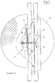
- the thread guide device 13 also has a holder 36 for a thread monitor needle 17, which is fastened to the housing 27 of the thread guide device 13 with a pivot bearing 37. It can be seen from FIGS. 3, 4 that the thread monitor needle 17 serves to deflect the thread F coming from the bobbin 24 to the winding machine 11.
- the needle 17 is arranged such that it holds the thread between the clamping jaw 30 and the abutment 29 together with a pre-brake rod 15k in such a way that it runs without contact between the two aforementioned components 29,30.
- the distance x is thus available to the thread between the two components 29, 30 and the guard needle 17, as well as the pre-brake rod 15k, hold the thread F at x / 2.
- pre-brake rod 15k there are two further pre-brake rods 15s and 15m, the brake rod 15s being aligned with respect to the axis 39 of the bobbin 24 or with respect to the thread clamp 14 in the same way as the pre-brake rod 15k. All pre-brake rods 15 are arranged parallel and vertically to one another. As a result, they run parallel to the gate strut 26. In order to achieve the thread course of the thread F described above, both pre-brake rods 15k, 15s cannot be adjusted during winding operation.
- a third pre-brake rod 15m is provided, which is arranged such that the thread F forms a more or less large loop 38.
- the loop 38 can be reduced in size by moving the middle brake rod 15m to the dot-dash position 15m '. There is hardly any wrapping of the pre-brake rods 15, which is sufficient to press the thread F against the pre-brake rod 15k, so that the non-contact thread path in the area of the thread clamp 14 is guaranteed.
- the pre-brake rods 15 are used in the creel 10 with different settings of their pre-brake rod 15m.
- the position shown in FIG. 4 is used in the area of those bobbins 24 that are closest to the winding machine 11, in which the free-running thread length is the shortest and the influence of the ambient air on the thread by air friction is the least.
- the loop 38 provides a corresponding action on the thread F, which is consequently tensioned just as strongly as a thread F which runs from an end region 10 ′′ of the creel 10. In this area 10 ′′, an additional frictional application of the thread F is not necessary, so that the pre-brake rod assumes the position 15 m ′ shown in FIG.
- Fig.4 shows that the pre-brake rod 15k is hollow and has an air nozzle 18, namely a hole.
- compressed air is applied to the cavity 39 of the pre-brake rod 15k, compressed air flows out through the air nozzle 18, which is directed at the thread clamp 14, in particular at the area between the clamping jaw 30 and the abutment 29.
- a plurality of air nozzles 18 are arranged one above the other, this results in vertical to the plane of the illustration 4 shows an air curtain 19 which can coat a greater height of the thread clamp 14, which may be necessary since, for example, the clamping jaw 30 and its abutment 29 extend over a larger vertical area.
- At a Preliminary brake rod 15k there are several air nozzles 18 one above the other for several winding positions.
- the cavities 29 of several mutually parallel pre-brake rods 15k of different gate field columns can be pressurized together by compressed air. This results in a simultaneous cleaning of many thread clamps 14, not only insofar as they are assigned to a single pre-brake rod 15k. For example, the thread clamps 14 of an entire creel 20 or even all creel 20 are cleaned.
- the vertical pre-brake rods 15k can be moved horizontally, that is to say transversely to their longitudinal extent, in order to blow the thread clamps 14 over their entire width. This takes place expediently during a bobbin change, since then the contactless thread guidance of the thread F between the clamping jaw 30 and the abutment 29 is not provided.
- the pre-brake rods 15k, 15s on the one hand and 15m on the other hand are moved apart so far that the thread F can be pulled through the bobbin 24 into the clamping device 13 with ease. Thereafter, the pre-brake rods 15 are moved back into the positions shown in FIGS. 3, 4 so that their wrapping is achieved by the thread.
Landscapes
- Engineering & Computer Science (AREA)
- Textile Engineering (AREA)
- Quality & Reliability (AREA)
- Warping, Beaming, Or Leasing (AREA)
- Financial Or Insurance-Related Operations Such As Payment And Settlement (AREA)
Applications Claiming Priority (2)
| Application Number | Priority Date | Filing Date | Title |
|---|---|---|---|
| DE9306680U | 1993-05-04 | ||
| DE9306680U DE9306680U1 (de) | 1993-05-04 | 1993-05-04 | Spulengatter |
Publications (3)
| Publication Number | Publication Date |
|---|---|
| EP0625599A1 true EP0625599A1 (fr) | 1994-11-23 |
| EP0625599B1 EP0625599B1 (fr) | 1996-09-25 |
| EP0625599B2 EP0625599B2 (fr) | 2001-09-26 |
Family
ID=6892790
Family Applications (1)
| Application Number | Title | Priority Date | Filing Date |
|---|---|---|---|
| EP94106733A Expired - Lifetime EP0625599B2 (fr) | 1993-05-04 | 1994-04-29 | Cantre |
Country Status (3)
| Country | Link |
|---|---|
| EP (1) | EP0625599B2 (fr) |
| DE (2) | DE9306680U1 (fr) |
| ES (1) | ES2096371T3 (fr) |
Families Citing this family (4)
| Publication number | Priority date | Publication date | Assignee | Title |
|---|---|---|---|---|
| DE4440077C1 (de) * | 1994-11-10 | 1996-04-11 | Mayer Textilmaschf | Abblasvorrichtung zum Reinigen von Arbeitsbereichen fadenverarbeitender Einrichtungen |
| DE29608169U1 (de) * | 1996-05-06 | 1997-09-04 | Sucker-Müller-Hacoba GmbH & Co., 41063 Mönchengladbach | Wickelvorrichtung für Fäden von Spulengattern |
| DE19823613A1 (de) * | 1998-05-27 | 1999-12-02 | Sucker Mueller Hacoba Gmbh | Fadenbremsvorrichtung |
| DE202005015262U1 (de) * | 2005-09-27 | 2006-11-16 | Autefa Automation Gmbh | Gatterablauf |
Citations (6)
| Publication number | Priority date | Publication date | Assignee | Title |
|---|---|---|---|---|
| BE349287A (fr) * | ||||
| US3393712A (en) * | 1965-04-15 | 1968-07-23 | Machf L Te Strake Deurne Nv | Releasable thread clamp |
| DE3100880A1 (de) * | 1981-01-14 | 1982-07-29 | Maschinenfabrik Benninger AG, 9240 Uzwil | "spulengatter fuer zettel- oder schaermaschinen" |
| DE3141727A1 (de) * | 1981-10-21 | 1983-04-28 | W. Schlafhorst & Co, 4050 Mönchengladbach | Blaswagen eines gatters |
| DE4030940C1 (en) * | 1990-09-29 | 1992-04-02 | Memminger-Iro Gmbh, 7290 Freudenstadt, De | Closed reel permits effective removal of fibre dusts - has housing with air guiding pipe, located in air circulating system having blowers and filter to separate lint, etc. |
| DE4213859A1 (de) * | 1991-05-01 | 1992-11-05 | Benninger Ag Maschf | Spulengatter, insbesondere zettelgatter |
Family Cites Families (6)
| Publication number | Priority date | Publication date | Assignee | Title |
|---|---|---|---|---|
| US2547072A (en) † | 1946-07-16 | 1951-04-03 | American Viscose Corp | Creel |
| CH555905A (de) * | 1973-01-17 | 1974-11-15 | Benninger Ag Maschf | Fadenfuehrungs- und ueberwachungsvorrichtung an einem spulengatter. |
| CH622560A5 (fr) * | 1977-10-24 | 1981-04-15 | Benninger Ag Maschf | |
| DE3436714A1 (de) * | 1984-10-06 | 1986-04-17 | Hacoba Textilmaschinen Gmbh & Co Kg, 5600 Wuppertal | Spulengatter fuer zettel- oder schaermaschine und verfahren zur steuerung der fadenklemmen eines spulengatters |
| CH681634A5 (en) * | 1990-07-16 | 1993-04-30 | Benninger Ag Maschf | Warp winding machine - includes creel with tension and detector which in event of break closes magnetic switch to stop winder |
| CH683193A5 (de) † | 1991-04-24 | 1994-01-31 | Benninger Ag Maschf | Vorrichtung zur Ueberwachung des Fadenlaufs an einem Spulengatter. |
-
1993
- 1993-05-04 DE DE9306680U patent/DE9306680U1/de not_active Expired - Lifetime
-
1994
- 1994-04-29 ES ES94106733T patent/ES2096371T3/es not_active Expired - Lifetime
- 1994-04-29 DE DE59400720T patent/DE59400720D1/de not_active Expired - Fee Related
- 1994-04-29 EP EP94106733A patent/EP0625599B2/fr not_active Expired - Lifetime
Patent Citations (6)
| Publication number | Priority date | Publication date | Assignee | Title |
|---|---|---|---|---|
| BE349287A (fr) * | ||||
| US3393712A (en) * | 1965-04-15 | 1968-07-23 | Machf L Te Strake Deurne Nv | Releasable thread clamp |
| DE3100880A1 (de) * | 1981-01-14 | 1982-07-29 | Maschinenfabrik Benninger AG, 9240 Uzwil | "spulengatter fuer zettel- oder schaermaschinen" |
| DE3141727A1 (de) * | 1981-10-21 | 1983-04-28 | W. Schlafhorst & Co, 4050 Mönchengladbach | Blaswagen eines gatters |
| DE4030940C1 (en) * | 1990-09-29 | 1992-04-02 | Memminger-Iro Gmbh, 7290 Freudenstadt, De | Closed reel permits effective removal of fibre dusts - has housing with air guiding pipe, located in air circulating system having blowers and filter to separate lint, etc. |
| DE4213859A1 (de) * | 1991-05-01 | 1992-11-05 | Benninger Ag Maschf | Spulengatter, insbesondere zettelgatter |
Also Published As
| Publication number | Publication date |
|---|---|
| ES2096371T3 (es) | 1997-03-01 |
| DE59400720D1 (de) | 1996-10-31 |
| EP0625599B1 (fr) | 1996-09-25 |
| EP0625599B2 (fr) | 2001-09-26 |
| DE9306680U1 (de) | 1993-07-01 |
Similar Documents
| Publication | Publication Date | Title |
|---|---|---|
| DE2841210C2 (de) | Einrichtung zur Ballonbegrenzung an einem Spulengatter | |
| EP3371360B1 (fr) | Dispositif et procédé de fabrication de tricot | |
| DE102017010143A1 (de) | Vorrichtung zum Abziehen und Aufwickeln mehrerer Fäden | |
| EP0365472B1 (fr) | Dispositif pour enfiler un fil dans un métier à tisser | |
| DE1510800C3 (de) | Vorrichtung zum selbsttätigen Spulenwechsel an Doppeldrahtzwirnmaschinen | |
| EP2284304B1 (fr) | Ourdissoir à chaîne de motif et procédé de production d'une chaîne de motif | |
| EP0625599B1 (fr) | Cantre | |
| DE2360507A1 (de) | Spulengatter | |
| EP0411382B1 (fr) | Dispositif de préparation pour dévider l'extrémité de fil dans le bout du fuseau | |
| EP1143052B1 (fr) | Procédé et dispositif pour diviser les fils sur un ourdissoir | |
| DE10239334B4 (de) | Fadenspulmaschine mit einem Spannungsdetektor | |
| EP1960301B1 (fr) | Methode et dispositif d'enroulement d'un fil | |
| EP2824054B1 (fr) | Poste de travail d'une machine textile fabriquant des bobines croisées | |
| DE69911214T2 (de) | Verschlingungsschutz für einen fadenlieferspeicher | |
| EP1917204B1 (fr) | Tete de bobinage de machine textile produisant des bobines croisees | |
| EP1954617B1 (fr) | Buse d'air d'aspiration pour une machine textile | |
| EP1446521A1 (fr) | Machine a texturer | |
| EP0904436B1 (fr) | Dispositif d'enroulement pour fils de cantres | |
| DE4213859A1 (de) | Spulengatter, insbesondere zettelgatter | |
| DE3206478A1 (de) | Vorrichtung zum abziehen von garnenden an textilspulen | |
| DE10336683A1 (de) | Spulstelle für eine Kreuzspulen herstellende Textilmaschine | |
| EP3165639B1 (fr) | Frein de fil extérieur, machine de câblage et de cordage comprenant un frein de fil extérieur et procédé de fonctionnement d'une telle machine de câblage ou de torsadage | |
| DE20113230U1 (de) | Spulenmagazin für Schussfadenvorratsspulen an Greiferwebmaschinen | |
| DE2915915A1 (de) | Kablierfadenzufuehrungsvorrichtung | |
| WO2007090425A1 (fr) | Procédé et dispositif pour tirer un fil par en haut |
Legal Events
| Date | Code | Title | Description |
|---|---|---|---|
| PUAI | Public reference made under article 153(3) epc to a published international application that has entered the european phase |
Free format text: ORIGINAL CODE: 0009012 |
|
| AK | Designated contracting states |
Kind code of ref document: A1 Designated state(s): CH DE ES FR GB IT LI |
|
| 17P | Request for examination filed |
Effective date: 19950202 |
|
| GRAG | Despatch of communication of intention to grant |
Free format text: ORIGINAL CODE: EPIDOS AGRA |
|
| GRAH | Despatch of communication of intention to grant a patent |
Free format text: ORIGINAL CODE: EPIDOS IGRA |
|
| 17Q | First examination report despatched |
Effective date: 19960215 |
|
| GRAH | Despatch of communication of intention to grant a patent |
Free format text: ORIGINAL CODE: EPIDOS IGRA |
|
| GRAA | (expected) grant |
Free format text: ORIGINAL CODE: 0009210 |
|
| AK | Designated contracting states |
Kind code of ref document: B1 Designated state(s): CH DE ES FR GB IT LI |
|
| PG25 | Lapsed in a contracting state [announced via postgrant information from national office to epo] |
Ref country code: FR Free format text: LAPSE BECAUSE OF FAILURE TO SUBMIT A TRANSLATION OF THE DESCRIPTION OR TO PAY THE FEE WITHIN THE PRESCRIBED TIME-LIMIT Effective date: 19960925 |
|
| REG | Reference to a national code |
Ref country code: CH Ref legal event code: NV Representative=s name: E. BLUM & CO. PATENTANWAELTE |
|
| REF | Corresponds to: |
Ref document number: 59400720 Country of ref document: DE Date of ref document: 19961031 |
|
| GBT | Gb: translation of ep patent filed (gb section 77(6)(a)/1977) |
Effective date: 19961127 |
|
| ITF | It: translation for a ep patent filed | ||
| ET | Fr: translation filed | ||
| REG | Reference to a national code |
Ref country code: ES Ref legal event code: FG2A Ref document number: 2096371 Country of ref document: ES Kind code of ref document: T3 |
|
| REG | Reference to a national code |
Ref country code: GB Ref legal event code: 732E |
|
| RAP2 | Party data changed (patent owner data changed or rights of a patent transferred) |
Owner name: SUCKER-MUELLER-HACOBA GMBH & CO. |
|
| PLBQ | Unpublished change to opponent data |
Free format text: ORIGINAL CODE: EPIDOS OPPO |
|
| PLAV | Examination of admissibility of opposition |
Free format text: ORIGINAL CODE: EPIDOS OPEX |
|
| PLBI | Opposition filed |
Free format text: ORIGINAL CODE: 0009260 |
|
| PLAV | Examination of admissibility of opposition |
Free format text: ORIGINAL CODE: EPIDOS OPEX |
|
| PLAV | Examination of admissibility of opposition |
Free format text: ORIGINAL CODE: EPIDOS OPEX |
|
| PLBF | Reply of patent proprietor to notice(s) of opposition |
Free format text: ORIGINAL CODE: EPIDOS OBSO |
|
| REG | Reference to a national code |
Ref country code: CH Ref legal event code: PUE Owner name: HACOBA TEXTILMASCHINEN GMBH & CO KG TRANSFER- SUCK |
|
| 26 | Opposition filed |
Opponent name: BENNINGER AG Effective date: 19970618 |
|
| PLBF | Reply of patent proprietor to notice(s) of opposition |
Free format text: ORIGINAL CODE: EPIDOS OBSO |
|
| REG | Reference to a national code |
Ref country code: FR Ref legal event code: TP |
|
| PLBF | Reply of patent proprietor to notice(s) of opposition |
Free format text: ORIGINAL CODE: EPIDOS OBSO |
|
| PLAW | Interlocutory decision in opposition |
Free format text: ORIGINAL CODE: EPIDOS IDOP |
|
| PLAW | Interlocutory decision in opposition |
Free format text: ORIGINAL CODE: EPIDOS IDOP |
|
| PGFP | Annual fee paid to national office [announced via postgrant information from national office to epo] |
Ref country code: ES Payment date: 20010402 Year of fee payment: 8 |
|
| PGFP | Annual fee paid to national office [announced via postgrant information from national office to epo] |
Ref country code: GB Payment date: 20010425 Year of fee payment: 8 Ref country code: FR Payment date: 20010425 Year of fee payment: 8 |
|
| PUAH | Patent maintained in amended form |
Free format text: ORIGINAL CODE: 0009272 |
|
| STAA | Information on the status of an ep patent application or granted ep patent |
Free format text: STATUS: PATENT MAINTAINED AS AMENDED |
|
| 27A | Patent maintained in amended form |
Effective date: 20010926 |
|
| AK | Designated contracting states |
Kind code of ref document: B2 Designated state(s): CH DE ES FR GB IT LI |
|
| REG | Reference to a national code |
Ref country code: CH Ref legal event code: AEN Free format text: AUFRECHTERHALTUNG DES PATENTES IN GEAENDERTER FORM |
|
| GBTA | Gb: translation of amended ep patent filed (gb section 77(6)(b)/1977) | ||
| REG | Reference to a national code |
Ref country code: GB Ref legal event code: IF02 |
|
| PG25 | Lapsed in a contracting state [announced via postgrant information from national office to epo] |
Ref country code: ES Free format text: LAPSE BECAUSE OF FAILURE TO SUBMIT A TRANSLATION OF THE DESCRIPTION OR TO PAY THE FEE WITHIN THE PRESCRIBED TIME-LIMIT Effective date: 20020106 |
|
| PG25 | Lapsed in a contracting state [announced via postgrant information from national office to epo] |
Ref country code: GB Free format text: LAPSE BECAUSE OF NON-PAYMENT OF DUE FEES Effective date: 20020429 |
|
| EN | Fr: translation not filed | ||
| GBPC | Gb: european patent ceased through non-payment of renewal fee |
Effective date: 20020429 |
|
| REG | Reference to a national code |
Ref country code: CH Ref legal event code: PUE Owner name: MOENUS TEXTILMASCHINEN GMBH Free format text: SUCKER-MUELLER-HACOBA GMBH & CO.#KREFELDER STRASSE 690#D-41066 MOENCHENGLADBACH (DE) -TRANSFER TO- MOENUS TEXTILMASCHINEN GMBH#HEINRICH-HERTZ-STRASSE 28#07552 GERA (DE) |
|
| PGFP | Annual fee paid to national office [announced via postgrant information from national office to epo] |
Ref country code: CH Payment date: 20070426 Year of fee payment: 14 |
|
| PGFP | Annual fee paid to national office [announced via postgrant information from national office to epo] |
Ref country code: DE Payment date: 20070509 Year of fee payment: 14 |
|
| REG | Reference to a national code |
Ref country code: CH Ref legal event code: PFA Owner name: MOENUS TEXTILMASCHINEN GMBH Free format text: MOENUS TEXTILMASCHINEN GMBH#HEINRICH-HERTZ-STRASSE 28#07552 GERA (DE) -TRANSFER TO- MOENUS TEXTILMASCHINEN GMBH#HEINRICH-HERTZ-STRASSE 28#07552 GERA (DE) |
|
| PGFP | Annual fee paid to national office [announced via postgrant information from national office to epo] |
Ref country code: IT Payment date: 20070619 Year of fee payment: 14 |
|
| REG | Reference to a national code |
Ref country code: CH Ref legal event code: PL |
|
| PG25 | Lapsed in a contracting state [announced via postgrant information from national office to epo] |
Ref country code: LI Free format text: LAPSE BECAUSE OF NON-PAYMENT OF DUE FEES Effective date: 20080430 Ref country code: DE Free format text: LAPSE BECAUSE OF NON-PAYMENT OF DUE FEES Effective date: 20081101 Ref country code: CH Free format text: LAPSE BECAUSE OF NON-PAYMENT OF DUE FEES Effective date: 20080430 |
|
| PG25 | Lapsed in a contracting state [announced via postgrant information from national office to epo] |
Ref country code: IT Free format text: LAPSE BECAUSE OF NON-PAYMENT OF DUE FEES Effective date: 20080429 |