EP0625697B1 - Véhicule équipé d'un dispositif de pesage - Google Patents
Véhicule équipé d'un dispositif de pesage Download PDFInfo
- Publication number
- EP0625697B1 EP0625697B1 EP94850078A EP94850078A EP0625697B1 EP 0625697 B1 EP0625697 B1 EP 0625697B1 EP 94850078 A EP94850078 A EP 94850078A EP 94850078 A EP94850078 A EP 94850078A EP 0625697 B1 EP0625697 B1 EP 0625697B1
- Authority
- EP
- European Patent Office
- Prior art keywords
- weight
- vehicle
- value
- axle
- axle assembly
- Prior art date
- Legal status (The legal status is an assumption and is not a legal conclusion. Google has not performed a legal analysis and makes no representation as to the accuracy of the status listed.)
- Expired - Lifetime
Links
- 238000005303 weighing Methods 0.000 title claims abstract description 37
- 230000000712 assembly Effects 0.000 claims abstract description 36
- 238000000429 assembly Methods 0.000 claims abstract description 36
- 238000005259 measurement Methods 0.000 claims abstract description 35
- 238000012545 processing Methods 0.000 claims abstract description 28
- 238000000034 method Methods 0.000 claims abstract description 25
- 239000000725 suspension Substances 0.000 claims description 18
- 238000006073 displacement reaction Methods 0.000 claims description 10
- 238000013479 data entry Methods 0.000 claims description 5
- 230000006870 function Effects 0.000 description 49
- 238000006243 chemical reaction Methods 0.000 description 11
- 230000008569 process Effects 0.000 description 6
- 230000003213 activating effect Effects 0.000 description 5
- 230000004913 activation Effects 0.000 description 3
- 238000010586 diagram Methods 0.000 description 3
- 230000001105 regulatory effect Effects 0.000 description 3
- 230000008859 change Effects 0.000 description 2
- 239000004020 conductor Substances 0.000 description 2
- 230000007423 decrease Effects 0.000 description 2
- 230000000007 visual effect Effects 0.000 description 2
- 230000006978 adaptation Effects 0.000 description 1
- 239000003990 capacitor Substances 0.000 description 1
- 239000000969 carrier Substances 0.000 description 1
- 230000001276 controlling effect Effects 0.000 description 1
- 238000012423 maintenance Methods 0.000 description 1
- 238000012544 monitoring process Methods 0.000 description 1
- 230000004044 response Effects 0.000 description 1
Images

Classifications
-
- G—PHYSICS
- G01—MEASURING; TESTING
- G01G—WEIGHING
- G01G23/00—Auxiliary devices for weighing apparatus
- G01G23/01—Testing or calibrating of weighing apparatus
-
- G—PHYSICS
- G01—MEASURING; TESTING
- G01G—WEIGHING
- G01G19/00—Weighing apparatus or methods adapted for special purposes not provided for in the preceding groups
- G01G19/08—Weighing apparatus or methods adapted for special purposes not provided for in the preceding groups for incorporation in vehicles
- G01G19/10—Weighing apparatus or methods adapted for special purposes not provided for in the preceding groups for incorporation in vehicles having fluid weight-sensitive devices
Definitions
- the present invention relates to a weighing system capable of being installed on board a vehicle for providing accurate weight measurements of the vehicle through a range of vehicle weights.
- the weight of a vehicle is often of crucial importance, especially to carriers in the trucking industry.
- the cost of delivering a load for commercial purposes is assessed to the customer according to the weight of the load and the distance it must travel. Knowledge of load weight is therefore necessary to ensure that the customer is assessed the full price of transporting the load. Weight information can also be used to optimize the load at or near the vehicle's maximum capacity.
- the weight of commercial cargo vehicles is also important from the perspective of public safety and highway maintenance. Overloading a commercial cargo vehicle can create a hazard by reducing the vehicle's stability and braking ability. An overloaded commercial cargo vehicle also causes significantly greater wear to public highways and to the vehicle itself. Governments therefore regulate vehicle weight by specifying a maximum legal load limit and fining vehicle operators for any overage.
- the load limit laws have been enforced using the same stationary scales relied on by operators to determine a vehicle's loaded weight for pricing purposes. Law enforcement agencies have even been known to use the records of privately operated stationary scales in enforcing the load limit laws. Vehicle operators may therefore lack the ability to detect non-compliance before being subject to liability for overloading.
- an on-board weighing system offers significant advantages over stationary scales.
- vehicle operators can determine vehicle weight at the loading dock or while under way to ensure accurate freight charge calculation, optimize load weight, and voluntarily comply with load limits.
- the devices have employed various weight sensor apparatus for sensing the weight of the vehicle's load, including load cells, strain gauges, displacement transducers on leaf or coil spring suspended vehicles, or pressure transducers on height-levelled, air spring suspended vehicles.
- the various weight sensor apparatus generate an electrical signal related to the load weight of the vehicle.
- the prior devices further comprise a cab-mounted read-out device for displaying the vehicle's load weight in response to a weight sensor signal.
- the read-out devices operate similarly to a simple gauge and may have zeroing, offset, or gain screw adjustments.
- Read-out devices of this type are capable of calibrating to only a single load weight. To calibrate the device, the vehicle is weighed at a stationary scale to determine its weight with a given load. The screw adjustments are then adjusted until the device displays the correct weight of the given load. After calibration, the device is accurate at the given load weight. However, the calibration procedure does not guarantee that the device will read accurately for other than the given calibrated load weight. Re-calibration of the device to another load weight affects the accuracy of the device at the previously calibrated load weight. Since the devices are capable of calibrating to only a single load weight, the devices can assure accuracy at only the single load weight.
- the Perini system determines a vehicle's weight from a weight related signal generated by a weight sensor apparatus.
- a cab mounted read-out device receives the signal and determines the vehicle weight.
- the read-out device includes an offset amplifier with a screw adjustment for shifting the DC voltage level of the signal.
- the signal is then converted by an analog-to-digital converter to a digital value.
- the digital value is used as an address for looking up the vehicle weight in a conversion table stored in a read only memory (ROM).
- the read-out device has two adjustments for calibrating the system to a weight related signal generated by a particular weight sensor apparatus.
- a conversion table which most correctly correlates the weight related signal to vehicle weights is selected out of a plurality of conversion tables stored in the ROM using a set of switches.
- the offset adjustment screw is tuned until the correct vehicle weight is displayed by the read-out device.
- the read-out device can determine vehicle weight fairly accurately through a range of vehicle weights.
- the Perini weighing system has two major disadvantages.
- various weight sensor apparatus have different characteristics and produce weight related signals that correlate differently to the vehicle weight. Since their signals correlate differently to vehicle weight, each weight sensor apparatus typically requires a different conversion table which correctly correlates the signal to vehicle weights. If the correct conversion table for a weight sensor apparatus is not included in the ROM, the weighing system can not accurately determine vehicle weight from the signal generated by the weight sensor apparatus. A less accurate conversion table may be selected instead, but inaccurate and unreliable vehicle weight measurements will result.
- a commensurate number of conversion tables must be stored in the ROM. However, increasing the number of tables stored in the ROM only increases the likelihood that the correct conversion table is included. It does not guarantee that the correct conversion table is included. Also, increasing the number of conversion tables increases the storage requirements of the ROM, consequently increasing the cost and complexity of the system.
- the second major disadvantage with the Perini weighing system is that the calibration of the system is not easily reproducible. To accommodate trailer switching, it is desirable to be able to reset the weighing system for a trailer that was previously calibrated without having to repeat the calibration process involving the use of a stationary scale. Calibrating the Perini weighing system additionally involves tuning an adjustment screw. Since adjustment screws are difficult to accurately reset to a previously calibrated setting, the calibration of the Perini weighing system is not easily reproducible.
- U.S. Patent No. 4,588,038 teaches a method for measuring a load weight carried by a vehicle wherein the load weight is measured by subtracting the weight of the vehicle when it is loaded from the empty weight of the vehicle.
- the load weight is supported by suspension cylinders of the vehicle.
- the method comprises the steps of detecting the pressures in all suspension cylinders sequentially during a given period of time while the vehicle is vibrating, calculating the weights applied to all the suspension cylinders based on the detected pressures and the cross-sectional area of the cylinders, and obtaining an average value of the calculated weight at the given period of time.
- An air spring load monitoring system is known through U.S. 5,167,289. According to this document the system provides the operator with an onboard visual display of the load distribution imposed on each axle from front to rear of a truck and trailer. Pneumatic transducers are arranged to produce analog output signal proportional to the internal air pressure of each air spring as an accurate indicator of payload distribution.
- the vehicle weighing apparatus and method of the present invention provides the ability to easily and quickly calibrate and accurately determine weight measurements of a vehicle throughout a range.
- an electrical signal related to the weight of the vehicle and load on an axle assembly of the vehicle is processed using two values or constants to determine a weight measurement.
- the invention accurately determines the weight measurement through a range of vehicle loads from empty to fully loaded.
- a weight sensor assembly generates a signal related to a portion of the weight of a vehicle and load which is supported on an axle assembly.
- the signal is processed using a ratio value and an unsprung weight value associated with the axle assembly to determine the weight of the axle assembly.
- the axle assembly weight is the weight applied by the axle assembly against a road or other surface supporting the axle assembly and includes the weight of the axles, wheels, tires, suspension, and other components which form the axle assembly as well as the weight of a portion of the vehicle and load supported on the axle assembly.
- the ratio value corresponds to the ratio of pounds or other unit of weight per increment of a digital value of the signal.
- the unsprung weight value corresponds to the portion of the weight of the axle assembly not being supported by the axle assembly, i.e. the weight of the components which form the axle assembly, but not the weight of the vehicle and load supported on the axle assembly.
- the signal is processed by converting it to a digital value, then multiplying the digital value by the ratio value and adding the unsprung weight value to the product of the digital value and the ratio value.
- the weights of additional axle assemblies of the vehicle are determined in a similar manner by processing a signal related to the weight supported on an additional axle assembly using ratio and unsprung weight values associated with the respective axle assembly.
- the constants are calibrated according to the invention to provide accurate weight measurements throughout a range of vehicle loads by determining the actual weight measurement with a stationary scale at two reference loads, e.g., empty and fully loaded.
- the ratio value is calibrated to equal the ratio of the difference in the actual axle assembly weights at the two reference loads to the difference in the digital value of the weight related signal at the two reference loads.
- the unsprung weight value is calibrated to equal the actual axle assembly weight at a first of the reference loads minus the product of the ratio value and the digital value of the weight related signal at the first reference load.
- Axle weights subsequently determined according to the invention using the calibrated ratio and unsprung weight values are accurate for all vehicle loads in a range between the two reference loads.
- a weight measurement of a vehicle can be accurately determined if two constants are known, trailer switching is easily accommodated without recalibration.
- the constants for determining various weight measurements of a trailer can be marked on the trailer after an initial calibration and used for weight measurement determinations when subsequently hitched to other tractors.
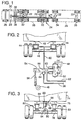
- Fig. 1 is a schematic view of a tractor/trailer rig with an on-board weighing system according to a preferred embodiment of the present invention.
- Fig. 2 is a schematic view of an air suspension adapted to serve as a sensor assembly according to a preferred embodiment of the invention for use in the on-board weighing system of Fig. 1.
- Fig. 3 is a schematic view of a sensor assembly according to another embodiment of the invention comprising a leaf spring suspension and a displacement transducer mounted between a frame and a frame supporting axle assembly of a vehicle for use in the on-board weighing system of Fig. 1.
- Fig. 4 is a front perspective view of a cab-mounted console in the on-board weighing system of Fig. 1 including the front panel.
- Fig. 5 is a rear view of the console in Fig. 4 including the back panel.
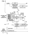
- Fig. 6 is a block diagram of a daughter board in the console of Fig. 4.
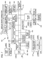
- Fig. 7 is a block diagram of a main board in the console of Fig. 4.
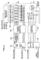
- Fig. 8 is a block diagram of a display board in the console of Fig. 4.
- an on-board weighing system comprises a processing and display unit 20 and one or more sensor assemblies 22.
- the weighing system is installable on a vehicle 24 to provide accurate vehicle weight measurements available on demand.
- the processing and display unit 20 is generally located in a cab portion 30 of the tractor 26.
- the sensor assemblies 22 can have various configurations and are generally associated one-to-one with axle assemblies 32-35 of the vehicle 24 to generate electrical signals related to a weight of the vehicle and any load carried on its respective axle assemblies.
- axle assembly is used herein to refer to a group of one or more axles, wheels and related equipment each of which supports a portion of a frame of the vehicle.
- the sensor assemblies can be configured to generate a signal related to other vehicle weight parameters such as the weight of a vehicle platform and load on a vehicle frame.
- the sensor assemblies 22 are electrically connected to the processing and display unit 20 with cables 38 to thereby transmit the weight related signals to the unit 20.
- the unit 20 processes the signals according to the invention to determine vehicle weight measurements and display the same.
- a large percentage of commercial cargo vehicles currently in use employs air suspensions.
- Typical air suspensions can be easily and inexpensively adapted to serve as a sensor assembly 22 for generating an electrical signal related to the weight of a vehicle and load on an axle assembly.
- a pair of air bags 44 is mounted between each axle 46 of a vehicle and its frame 48.
- the inflation of the air bags is regulated with a height-levelling valve 52 mounted to the vehicle frame and operated by a valve actuator arm 54 and push-rod 56 connected to the axle.
- the height levelling valve introduces additional compressed air to or exhausts air from the air bags through an air line 60 connecting the levelling valve and the air bags to support the vehicle frame at a predetermined height above the axle.
- the compressed air is typically supplied to the levelling valve 52 by a second air line 62 from an air compressor (not shown) driven by the vehicle's motor. Excess air is vented from an exhaust port 63.
- air bag inflation properly regulated by a height levelling valve, the internal pressure of the air bags is related to the weight of the vehicle supported on the air bags.
- Adaptation of the air suspension to serve as a weight sensor assembly is accomplished by attaching a conventional pressure transducer 64 to the air line 60 connecting the levelling valve 52 and the air bags 44.
- Pressure transducer attachment is readily effected by detaching the air line 60 from the levelling valve 52, then connecting the air line 60, levelling valve 52 and pressure transducer 64 with a tee connector 66.
- the pressure transducer 64 generates an electrical signal related to the internal pressure of the air bags, and hence related to the weight supported on the air suspension.
- the signal generated by the pressure transducer is transmitted to the processing and display unit 20 (Fig. 1) through the cable 38.
- the sensor assemblies 22 can be alternatively embodied in any apparatus capable of generating a signal related to a weight parameter of a vehicle.
- a vehicle 74 in which a frame 76 of the vehicle is suspended on an axle assembly 78 using two or more mechanical leaf or coil springs 80, the springs are compressed according to the weight of the vehicle and load on the springs.
- the distance separating the frame or underside 84 of the vehicle from the axle assembly is therefore related to the weight of the vehicle and load on the axle assembly.
- a displacement transducer 86 is mounted between the axle and the underside 84 of the vehicle.
- a typical displacement transducer suitable for this purpose comprises a housing 88 attached at one end 89 to the vehicle underside 84 and having a slidably extending rod 90 at an opposite end 91. A distal or extending end 94 of the rod 90 is attached to the axle assembly 78.
- a potentiometer (not shown) within the housing 88 and operatively engaged by the rod 90 generates an electrical signal related to the displacement of the vehicle frame 76 from the axle assembly 78 and hence related to the weight on the axle assembly.
- the displacement transducer 86 and mechanical springs 80 of an axle assembly 78 in a vehicle with a mechanical spring suspension can therefore serve as a sensor assembly 22 in accordance with the invention.
- the processing and display unit 20 comprises a generally box-shaped console 100.
- the console 100 has a mounting bracket 102 for mounting the console in a convenient location in a cab of the vehicle 24 such as above or below a dashboard.
- the console 100 further comprises a front panel 104 and a back panel 106.
- On the front panel 104 are a digital numeric display 108, light emitting diodes 110-128 for indicating unit status, data entry keys 130-133, and an on/off switch 136.
- On the back panel 106 are signal input ports 144-149, a power connector 152, and an RS-232 standard data input/output port 154.
- the weight related signals generated by the sensor assemblies 22 are received by the unit 20 over the cables 38 at the signal input ports 144-149.
- the signal input ports 144-149 and the cables 38 each comprises three conductors 156-158.
- the processing unit 20 provides DC power voltage and ground signals to a sensor assembly 22 on two of the conductors and receives the weight related signal from the sensor assembly on a third. Since six signal input ports are provided in the preferred embodiment, up to six weight related signals for up to six axle assemblies can be received and processed by the unit.
- the number of axle assemblies varies according to the vehicle on which the weighing system is installed. In the vehicle 24 shown in Fig. 1, for example, there are four axle assemblies. Therefore, only four of the signal input ports will be used when installed thereon. Other embodiments of the invention can include any number of signal input ports.
- the console 100 houses electronic circuitry for processing the weight related signals received at the signal ports 144-149.
- the circuitry is primarily located on three printed circuit boards including a main board 164 (Fig. 7), a display board 166 (Fig. 8), and a daughter board 168 (Fig. 6).
- the daughter board 168 provides circuitry including an analog multiplexer 176, channel select register 178, offset adjustment amplifier 180, and analog-to-digital converter 182 for selecting and converting one of the weight related signals from the signal input ports 144-149 to a digital value.
- the main board 164 provides processing circuitry including a microprocessor 186, a read-only memory (EPROM) 188, and a random-access memory (SRAM) 190 for determining vehicle weight measurements from the digitally converted, weight related signals.
- the main board 164 also provides circuitry including data registers 194-198, seven segment driver 200, current limiting resistors 202, pull-up resistors 204, and drive transistors 206 for indicating the vehicle weight measurements and unit status information on the display 108 and LEDs 110-128 (both on the display board 166).
- the display and daughter boards 166, 168 are attached to the main board 164 with connectors 170, 172, respectively, which also provide electrical interconnections between the circuitry on the boards.
- the unit 20 is preferably supplied with electrical power by an external 12 volt battery, such as a battery in an ignition system of the vehicle 24, which is connected to the unit at the power connector 152 (Fig. 5). From the 12 volt external source, power supply circuits 212, 214 on the daughter and main boards, respectively, provide the various regulated power voltages required by the circuitry on the boards.
- an external 12 volt battery such as a battery in an ignition system of the vehicle 24 which is connected to the unit at the power connector 152 (Fig. 5).
- 12 volt external source From the 12 volt external source, power supply circuits 212, 214 on the daughter and main boards, respectively, provide the various regulated power voltages required by the circuitry on the boards.
- the unit 20 can determine various vehicle weight measurements.
- the unit 20 is operative to determine the weights of each axle assembly of the vehicle, the gross vehicle weight, and the net vehicle weight.
- the particular weight measurement determined by the unit is selected by the vehicle operator using the data entry keys 130-133 and the function LEDs 110-122 (the LEDs in a row along the top of the front panel 104 in Fig. 4).
- Each of the function LEDs 110-122 indicate a function of the unit 20 that can be selected by the operator by activating two of the data entry keys 130, 131 labeled "select" and "enter.”
- the select key 130 When the select key 130 is first activated, the left-most or "KILO" LED 110 of the function LEDs 110-122 begins to flash, indicating that a corresponding function can be selected.
- Each further activation of the select key 130 causes the next function LED in sequence from left to right to flash.
- the enter key 131 is activated to select the function.
- a function is selected, its corresponding LED remains lit.
- the functions that can be selected in the preferred embodiment include the following: “KILO,” “SCAN,” “GVW,” “TARE,” “AXLE,” “PORT,” “TIME,” “DATE,” “CAL,” “EMPTY,” “FULL,” “RATIO,” and “UNSPRUNG WEIGHT.”
- the unit 20 processes the weight related signal associated with a selected one of the axle assemblies 32-35 of the vehicle 24 to determine a selected axle assembly weight.
- the selected axle assembly weight is the weight applied by the selected axle assembly against a road or other surface supporting the selected axle assembly and includes the weight of the axles, wheels, tires, suspension, and other components which form the selected axle assembly as well as the weight of a portion of the vehicle and load supported by the selected axle assembly.
- the axle assembly whose weight is determined is operator selectable.
- the "AXLE" function is selected as described above using the function LEDs 110-122 and the select and enter keys 130, 131.
- the AXLE function LED 114 When the AXLE function has been selected, the AXLE function LED 114 remains lit and the left-most LED 123 of the axle LEDs 123-128 (those in a row at the bottom of the front panel 104) flashes. Each subsequent activation of the select key 130 causes the next axle LED in sequence from left to right to flash. Activation of the enter key selects the axle assembly whose corresponding axle LED is flashing. Only one axle assembly at a time can be selected. After the axle assembly is selected, the AXLE function LED 114 is no longer lit.
- the processing of the selected axle assembly's weight related signal to determine the selected axle assembly's weight is carried out by the microprocessor (processor) 186 in accordance with the instructions of a program stored in the EPROM 188.
- the processor is a Z-80 type microprocessor.
- the weight related signal for the selected axle assembly is first converted to a digital value.
- the processor writes a channel select value corresponding to the selected axle assembly to the channel select register 178. This causes the multiplexer 176 to connect one of the signal input ports 144-149 where the selected axle assembly's weight related signal is received to a multiplexer output 220.
- the selected axle assembly's weight related signal is then offset adjusted by the amplifier 180 and converted to a digital value by the analog-to-digital converter 182.
- the digital value is then read by the processor into an internal register.
- the processor processes the digital value using two constants associated with the selected axle assembly.
- the constants are a ratio value and an unsprung weight value.
- the ratio and unsprung weight values characterize a relationship between the weight related signal of the selected axle assembly and its weight.
- the unsprung weight of an axle assembly is the portion of the axle assembly weight that is not supported on the axle assembly by the vehicle's suspension.
- the ratio value is a conversion or scaling factor for converting units of the weight related signal to units of weight, such as pounds.
- the ratio value is generally related to the active inner surface area of the air bags in the air suspension supporting the vehicle frame on the axle assembly. Separate ratio and unsprung weight values for each of the axle assemblies 32-35 are stored in the SRAM 190.
- a capacitor 224 provides backup power to the SRAM 190 in the event of a temporary interruption in power from the external battery to avoid loss of the constants.
- the processor comprises circuitry and software routines for adding, subtracting, multiplying and dividing which are used to process the digital value.
- the Z-80 microprocessor which is used in the preferred embodiment includes an arithmetic logic unit with adder and subtractor circuitry and software routines for performing multiplication and division with the logic unit's adder and subtractor circuitry.
- the processor determines the selected axle assembly's weight by multiplying the selected axle assembly's digital and ratio values to form a product value and adding the axle assembly's unsprung weight value to the product value. The sum of the unsprung weight and product values is, in the preferred embodiment, the selected axle assembly's weight in pounds.
- the processor displays the selected axle assembly weight in pounds on the display 108 using the display circuitry 194-206. However, if the "KILO" function is also selected, the processor further multiplies the weight of the selected axle assembly in pounds by a pounds-to-kilos conversion factor to determine the weight in kilos and displays the weight in kilos on the display 108.
- the unit 20 can instead be used to determine and display the gross vehicle weight by selecting the "GVW" function using the function LEDs 110-122 and the select and enter keys 130,131 as described above.
- the GVW LED 112 remains lit.
- the axle LEDs 123-128 corresponding to the "active" axle assemblies will also be lit.
- the unit determines the weight of each of the active axle assemblies as described above with the ratio and unsprung weight values of the respective axle assembly.
- the weights of the active axle assemblies are summed by the processor 186 to determine the gross vehicle weight.
- the gross vehicle weight is displayed on the numeric display 108 in pounds or, if the KILO function has been selected, in kilos.
- the "SCAN" function can also be selected as described above using the SCAN LED 111 and the keys 130, 131 to cause the unit 20 to determine the weights of all active axle assemblies 32-35 and the gross vehicle weight as described above and to display those weights in succession for intervals of approximately two seconds.
- the corresponding axle LED 123-128 is lit as its weight is displayed on the numeric display 108 to identify the displayed weight.
- the GVW LED 112 and the active axle LEDs are lit to identify when the gross vehicle weight is displayed.
- the unit 20 in the preferred embodiment also determines the net weight of the vehicle 24 when the "TARE" function is selected.
- the net weight of a vehicle is defined as the weight of the load alone, or the gross vehicle weight minus the unloaded weight of the vehicle itself.
- the unit 20 continuously determines and displays the difference between the current gross vehicle weight and the gross vehicle weight at the time the TARE function is selected.
- the weight determined and displayed by the unit 20 is the true net weight as defined above.
- the TARE function can also be used to simply measure a change in the gross vehicle weight. For example, by selecting the TARE function prior to adding an additional load to an already loaded vehicle, the weight of the additional load will be determined and displayed after loading. A negative change in the gross vehicle weight, such as when the TARE function is selected prior to removing a portion of the load, can also be determined and displayed.
- a "NEG" LED 228 on the numeric display 108 will light to indicate a negative net weight.
- Accurate axle weight measurements of an axle assembly through a range of loaded axle weights requires calibration of the ratio and unsprung weight values of the axle assembly at two different axle assembly weights in the preferred embodiment of the invention.
- the weight of the axle assembly is measured at a first weight, preferably at empty or no load on the axle assembly, using a stationary scale. While the selected axle assembly is at the first weight, the operator selects the "CAL" function as described above using the function LEDs 110-122 and select and enter keys 130, 131.
- the axle assembly calibrated by the CAL function is selected using the AXLE function as described above. When the CAL function is selected, the CAL LED 118 and the axle LED 123-128 of the selected axle assembly remain lit.
- the operator further selects the "EMPTY" function.
- EMPTY EMPTY
- a weight is displayed on the numeric display 108.
- the operator increases (by activating the right arrow key) or decreases (by activating the left arrow key) the displayed weight until the numeric display 108 displays the first weight as measured by the stationary scale.
- the first weight is then entered into the unit 20 by activating the enter key 131.
- the processor 186 (Fig. 7) stores the first weight in the SRAM 190.
- the processor 186 also converts the weight related signal for the selected axle assembly at the first weight to a digital value and stores the digital value in the SRAM 190.
- the weight of the axle assembly is changed to a second weight by loading the vehicle, preferably to a fully loaded weight.
- the second weight of the selected axle assembly is then measured on a stationary scale.
- the operator selects the "CAL" and "FULL” functions, adjusts the displayed weight with the arrow keys 132-133, and activates the enter key 131.
- the processor 186 will then store the entered second weight and the digital value of the selected axle assembly's weight related signal at the second weight to the SRAM 190.
- the processor 186 determines the ratio and unsprung weight values of the selected axle assembly.
- the processor subtracts the first weight from the second weight to find the difference between the two weights and subtracts the digital value at the first weight from the digital value at the second weight to find a difference between the digital values. Then, the difference between the first and second weights is divided by the difference in the digital values to find the ratio value.
- the processor subtracts the product of the ratio value and the digital value at the first weight from the first weight.
- the trailer or trailers 28, 29 hauled by the tractor 26 can be switched for another trailer whose axle assembly's ratio and unsprung weight values have already been calibrated without having to repeat the calibration procedure for the new trailers.
- the values can be entered directly into the unit 20.
- the operator first selects the axle assembly using the AXLE function. Second, the operator selects the CAL function, then the "RATIO" function. When the CAL and RATIO functions are selected, the CAL and RATIO LEDs 118, 121 are lit and the ratio value for the old axle assembly is displayed on the numeric display 108. The operator adjusts the displayed ratio value on the display 108 with the left and right arrow keys 132, 133 until the known ratio value of the new axle assembly is displayed, then enters the ratio value by activating the enter key 131. The unsprung weight value of the new axle assembly is similarly entered with the arrow and enter keys 131-133 after selecting the CAL and "UNSPRUNG WEIGHT" functions.
- a record of the ratio and unsprung weights of trailers used with the tractor 26 can be kept so that the ratio and unsprung weight values are available to enter into the unit 20 when switching trailers.
- the ratio and unsprung weight values of a trailer's axle assemblies can be marked in a convenient location on the trailer so that the values are readily available when switching trailers.
- the unit 20 provides further weight reporting capabilities in addition to providing a visual display of the weights on the numeric display 108.
- the unit 20 determines the weights of the active axle assemblies and the gross vehicle weight as described above.
- the unit then transmits a "report" including the weight information using transmitting/receiving circuitry 232 on the main board 164 (Fig. 7) to a device connected to the data input/output port 154 on the back panel 106 (Fig. 5).
- the data input/output port 154 is connectable to a printer, a computing device, a data transmitting device, or like devices. When the part 154 is connected to a printer, a printed record of the vehicle's weights can be provided. Remote reporting of the vehicle's weights can also be provided when the data port 154 is connected to a computing or data transmitting device.
- the unit 20 includes a real time clock circuit 236 on the main board 164 (Fig. 7).
- the correct time is set in the unit by selecting the "TIME” function with the function LEDs and select and enter keys 130-131, then entering the time using the left and right arrow keys 132, 133, numeric display 108, and the enter key 131.
- the correct time is set in a like manner using the "DATE" function.
- the real time clock circuit 236 tracks the current time. Later, when the PORT function is selected, the current time and date are included in the transmitted report.
- the data input/output port 154 and transmitting/receiving circuitry 232 can also be used to receive commands from an external source such as a computing device, to allow remote control of the unit 20.
- the commands recognized by the unit 20 are generally equivalent to the functions selectable with the function LEDs 110-122 and select and enter keys 130, 131.
- the commands allow a remote computing device to enter time, date, and ratio and unsprung weight values for a vehicle's axle assemblies.
- a remote computing device can also command the unit 20 to transmit report information.
- a sensor assembly 22 of the type shown in Fig. 2 generates a signal that is linearly related to the axle assembly weight when the pressure transducer 64 operates linearly and the height leveling valve 52 maintains the vehicle frame 48 at a constant height above the axle 46.
- the linearity of a signal generated by a sensor assembly of the type shown in Fig. 3 depends on the springs 80 compressing such that the displacement between the vehicle underside 84 and the axle 78 decreases linearly in relation to the weight of the vehicle 24 and on the displacement transducer 86 operating linearly.
Landscapes
- Physics & Mathematics (AREA)
- General Physics & Mathematics (AREA)
- Vehicle Body Suspensions (AREA)
- Float Valves (AREA)
- Measuring Volume Flow (AREA)
- Devices For Checking Fares Or Tickets At Control Points (AREA)
- Weight Measurement For Supplying Or Discharging Of Specified Amounts Of Material (AREA)
- Devices For Use In Laboratory Experiments (AREA)
- Traffic Control Systems (AREA)
- Testing Or Calibration Of Command Recording Devices (AREA)
Claims (28)
- Méthode de pesée d'un véhicule destinée à mesurer le poids en charge d'un ensemble d'axes du véhicule (32, 33, 34, 35), comprenant les phases consistant à:produire un signal électrique analogique correspondant au poids porté sur l'ensemble d'axes (32, 33, 34, 35);convertir le signal correspondant au poids sous forme numérique;associer une première valeur et une seconde valeur à l'ensemble d'axes (32, 33, 34, 35) du véhicule (26), la première valeur étant une valeur des éléments non suspendus correspondant au poids de l'ensemble d'axes (32, 33, 34, 35) et la seconde valeur étant une valeur de ratio correspondant au rapport d'une unité de poids par incrément du signal numérique fonction du poids;traiter le signal fonction du poids pour former une mesure de poids d'axes en ajoutant la valeur des éléments non suspendus au produit du signal numérique fonction du poids multiplié par la valeur de ratio; etindiquer visuellement la mesure de poids d'axes.
- Méthode de pesée d'un véhicule suivant la revendication 1, comprenant encore les étapes consistant à:associer la valeur des éléments non suspendus et la valeur de ratio à chacun d'un ou plus d'ensembles d'axes (32, 33, 34, 35) supplémentaires de véhicule (26);produire un signal électrique analogique correspondant au poids porté sur chacun des ensembles d'axes (32, 33, 34, 35) supplémentaires;convertir les signaux correspondant aux poids sous forme numérique; traiter les signaux correspondant aux poids pour former une mesure de poids d'axes pour chaque ensemble d'axes (32, 33, 34, 35) supplémentaire; etindiquer visuellement la mesure de poids d'axes.
- Méthode de pesée d'un véhicule suivant la revendication 2, comprenant encore les étapes consistant à:faire la somme de mesures de poids d'axes pour former une mesure brute de pesée du véhicule; etindiquer visuellement la mesure brute de poids du véhicule.
- Méthode de pesée d'un véhicule suivant la revendication 3, comprenant encore les étapes consistant à:indiquer visuellement séquentiellement la mesure de poids d'axes et la mesure brute de poids du véhicule.
- Méthode de pesée d'un véhicule suivant l'une quelconque des revendications 2 à 4, comprenant encore les étapes consistant à:déterminer la différence entre le poids brut du véhicule et un poids choisi, la différence étant le poids net du véhicule; etindiquer visuellement le poids net du véhicule.
- Méthode de pesée d'un véhicule suivant l'une quelconque des revendications 1 à 5, dans laquelle l'étape consistant à associer la valeur de ratio comprend les étapes consistant à:peser l'ensemble d'axes (32, 33, 34, 35) alors que le véhicule (26) a un premier poids;déterminer la valeur du signal correspondant au poids numérique quand le véhicule (26) est pesé audit premier poids;peser l'ensemble d'axes (32, 33, 34, 35) quand le véhicule a un second poids, le second poids étant supérieur au premier poids;déterminer la valeur du signal correspondant au poids numérique quand le véhicule (26) est pesé audit second poids; etdéterminer la valeur de ratio égale au rapport de la différence entre le poids de l'ensemble des axes audit premier poids et le poids de l'ensemble des axes audit second poids à la différence entre la valeur du signal numérique correspondant au poids audit premier poids et la valeur du signal numérique correspondant au poids à audit second poids.
- Méthode de pesée d'un véhicule suivant la revendication 6, dans laquelle ledit premier poids est la valeur de poids de véhicule à vide et ledit second poids est la valeur de poids de véhicule complètement plein.
- Méthode de pesée d'un véhicule suivant la revendication 6 ou 7, dans laquelle l'étape consistant à associer la valeur des éléments non suspendus comprend les étapes consistant à:déterminer la valeur des éléments non suspendus égale à la différence entre le poids de l'ensemble des axes audit premier poids et le produit de la valeur de ratio multipliée par la valeur du signal numérique correspondant au poids audit premier poids.
- Méthode de pesée d'un véhicule suivant la revendication 8, comprenant encore l'étape consistant à:faire entrer les poids d'ensembles d'axes auxdits premier et second poids dans une unité de traitement (20); etdéterminer la valeur de ratio et la valeur des éléments non suspendus avec l'unité de traitement.
- Méthode permettant de commuter une remorque d'un camion de combinaison tracteur/remorque dans la méthode de pesée de véhicule des revendications 2 à 9 comprenant les étapes consistant à:quand ayant commuté une remorque, faire entrer les valeurs des éléments non suspendus et les valeurs de ratio associées aux ensembles d'axes des remorques dans une unité de traitement (20); etassocier la valeur des éléments non suspendus et la valeur de ratio à chaque ensemble d'axes d'une première remorque;associer la valeur des éléments non suspendus et la valeur de ratio à chaque ensemble d'axes d'une seconde remorque;enregistrer les valeurs des éléments non suspendus et les valeurs de ratio associées aux ensembles d'axes des remorques;traiter les signaux correspondant aux poids pour former une mesure de poids d'axes pour chaque ensemble d'axes de remorque avec l'unité de traitement.
- Méthode suivant la revendication 10, comprenant encore l'étape consistant à:marquer la valeur des éléments non suspendus et la valeur de ratio associée à chaque ensemble d'axes de la remorque sur celle-ci.
- Appareil de mesure de pesée pour véhicules (26), dans lequel:caractérisé en ce queun ensemble capteur (22) est monté entre le châssis et un ensemble d'axes (32, 33, 34, 35) supportant le châssis pour produire un signal électrique analogique correspondant au poids porté sur l'ensemble d'axes (32, 33, 34, 35);un convertisseur analogue/numérique (182) est relié électriquement à l'ensemble capteur (22) destiné à produire un signal numérique correspondant au poids qui correspond audit signal électrique analogique; etune unité d'affichage (20) est prévue pour indiquer visuellement les mesures de poids du véhicule en fonction des données de poids d'axe;une unité de traitement (20) est prévue pour mettre en mémoire une valeur des éléments non suspendus correspondant au poids de l'ensemble d'axes (32, 33, 34, 35) et une valeur de ratio correspondant au rapport d'une unité de poids par incrément du signal numérique correspondant au poids associé à l'ensemble d'axes (32, 33, 34, 35), ladite unité de traitement étant prévue pour former une mesure de poids d'axe en ajoutant la valeur des éléments non suspendus au produit du signal numérique correspondant au poids mutiplié par la valeur de ratio.
- Appareil suivant la revendication 12, caractérisé en ce qu'une pluralité d'ensembles de capteurs (22) sont montés entre le châssis et plusieurs ensembles d'axes (32, 33, 34, 35) supportant le châssis du véhicule (26), chaque ensemble capteur (22) produisant un signal électrique analogique correspondant au poids porté sur l'ensemble d'axes (32, 33, 34, 35) respectifs du véhicule, à chaque ensemble d'axes étant ainsi associées une valeur de ratio et une valeur des éléments non suspendus; et en ce que l'unité de traitement (20 fonctionne pour produire des données de poids d'axe pour chaque ensemble d'axes (32, 33, 34, 35) en ajoutant sa valeur des éléments non suspendus associée à un produit de sa valeur de ratio associée multipliée par le signal numérique correspondant au poids porté sur l'ensemble des axes.
- Appareil suivant la revendication 12 ou 13, caractérisé en ce que ladite pluralité d'ensembles de capteurs (22) correspondent un à un à la pluralité d'ensembles d'axes (32, 33, 34, 35) du véhicule.
- Appareil suivant l'une quelconque des revendications 12 à 14, caractérisé en ce quel'unité de traitement (20) fonctionne encore pour produire des données de poids brut du véhicule en faisant la somme des données de poids d'axe pour les ensembles d'axes, et en ce quel'unité d'affichage (20) fonctionne pour virtuellement indiquer le poids brut du véhicule en fonction des données de poids brut du véhicule.
- Appareil suivant la revendication 15, caractérisé en ce que l'unité d'affichage (20) fonctionne pour virtuellement indiquer séquentiellement chaque poids d'ensembles d'axes et le poids brut du véhicule.
- Appareil suivant la revendication 15 ou 16, caractérisé en ce que:le processeur (20) fonctionne encore pour donner le poids net du véhicule en soustrayant une valeur choisie de poids des données de poids brut du véhicule, et en ce quel'unité d'affichage (20) fonctionne pour virtuellement indiquer le poids net du véhicule en fonction des données de poids net du véhicule.
- Appareil suivant l'une quelconque des revendications 12 à 17, caractérisé en ce que l'ensemble d'axes (32, 33, 34, 35) comprend plusieurs axes (46) du véhicule groupés pour supporter une partie de châssis (48) du véhicule.
- Appareil suivant l'une quelconque des revendications 12 à 17, caractérisé en ce que l'ensemble d'axes (32, 33, 34, 35) comprend un seul axe (46) du véhicule pour supporter une partie de châssis (48) du véhicule.
- Appareil suivant l'une quelconque des revendications 12 à 19, caractérisé en ce que l'ensemble capteur (22) comprend:un ressort pneumatique (44) d'un système de suspension pneumatique pour suspendre le châssis (48) du véhicule sur l'ensemble d'axes (32, 33, 34, 35); etun transducteur de pression (64) couplé au ressort pneumatique (44) pour produire un signal électrique analogique en fonction de la pression pneumatique à l'intérieur du ressort pneumatique (44), de manière à ce que le signal électrique analogique soit fonction du poids porté sur l'ensemble d'axes (32, 33, 34, 35).
- Appareil suivant la revendication 20, caractérisé en ce que la valeur de ratio est fonction de la surface interne active du ressort pneumatique (44).
- Appareil suivant l'une quelconque des revendications 12 à 19, caractérisé en ce que l'ensemble capteur (22) comprend:un transducteur de déplacement (88) pour produire un signal électrique analogique en fonction du déplacement du châssis (48) à partir de l'ensemble d'axes (32, 33, 34, 35) où le châssis (48) est suspendu à l'ensemble d'axes (32, 33, 34, 35) du véhicule sur un système (80) de suspension à ressort, de manière à ce que le signal électrique analogique soit fonction du poids porté sur l'ensemble d'axes (32, 33, 34, 35) du véhicule.
- Appareil suivant l'une quelconque des revendications 12 à 22, caractérisé en ce que l'unité de traitement (20), qui indique la mesure de poids du véhicule, comprend:au moins un canal, chaque canal ayant un port d'entrée (144, 145, 146, 147, 148, 149) pour recevoir un signal électrique analogique fonction du poids;un convertisseur analogique/numérique (182) pour convertir les signaux électriques analogiques fonctions du poids pour chaque canal; une mémoire pour enregistrer la valeur de ratio et la valeur des éléments non suspendus pour chaque canal;un processeur pour traiter respectivement les valeurs de ratio et les valeurs des éléments non suspendus pour former des données de poids indicatives de la mesure de poids du véhicule.
- Appareil suivant la revendication 23, caractérisé en ce que l'unité de traitement (20) comprend encore un port de sortie (154) pour transmettre l'information comprenant les données de poids à un autre dispositif électronique.
- Appareil suivant la revendication 23 ou 24, caractérisé en ce que l'unité de traitement (20) comprend encore une pluralité de clés d'entrée de données (130, 131, 132, 133) pour faire entrer la valeur de ratio et la valeur des éléments non suspendus dans la mémoire.
- Appareil suivant l'une quelconque des revendications 23 à 25, caractérisé en ce quel'unité de traitement (20) comprend encore:
une pluralité de clés d'entrée de données (130, 131, 132, 133) pour faire entrer une valeur de poids en charge pour un canal, quand le véhicule est chargé, et une valeur de poids à vide pour un canal, quand le véhicule est déchargé; etle processeur est encore prévu pour traiter le signal électrique analogique en fonction du poids du canal et les valeurs de poids en charge et à vide pour former la valeur de ratio et la valeur des éléments non suspendus. - Appareil suivant la revendication 26, caractérisé en ce que l'unité de traitement (20) fonctionne pour déterminer une première différence entre les poids en charge et à vide, et une seconde différence dans le signal numérique fonction du poids du canal, en charge et à vide, et pour diviser la première différence et la seconde différence pour former la valeur de ratio pour le canal.
- Appareil suivant la revendication 27, caractérisé en ce que l'unité de traitement (20) fonctionne pour former un produit égal à la valeur de ratio multipliée par le signal numérique fonction du poids du canal, à vide, et pour soustraire le produit de la valeur de poids à vide pour former la valeur des éléments non suspendus.
Applications Claiming Priority (2)
| Application Number | Priority Date | Filing Date | Title |
|---|---|---|---|
| US63140 | 1993-05-17 | ||
| US08/063,140 US5478974A (en) | 1993-05-17 | 1993-05-17 | On-board vehicle weighing system |
Publications (2)
| Publication Number | Publication Date |
|---|---|
| EP0625697A1 EP0625697A1 (fr) | 1994-11-23 |
| EP0625697B1 true EP0625697B1 (fr) | 1999-03-17 |
Family
ID=22047187
Family Applications (1)
| Application Number | Title | Priority Date | Filing Date |
|---|---|---|---|
| EP94850078A Expired - Lifetime EP0625697B1 (fr) | 1993-05-17 | 1994-05-09 | Véhicule équipé d'un dispositif de pesage |
Country Status (8)
| Country | Link |
|---|---|
| US (1) | US5478974A (fr) |
| EP (1) | EP0625697B1 (fr) |
| AT (1) | ATE177836T1 (fr) |
| AU (1) | AU677998B2 (fr) |
| CA (1) | CA2122766C (fr) |
| DE (1) | DE69417096T2 (fr) |
| ES (1) | ES2132367T3 (fr) |
| NZ (1) | NZ260494A (fr) |
Cited By (7)
| Publication number | Priority date | Publication date | Assignee | Title |
|---|---|---|---|---|
| US8374748B2 (en) | 2009-03-30 | 2013-02-12 | Lord Corporation | Land vehicles and systems with controllable suspension systems |
| US10670479B2 (en) | 2018-02-27 | 2020-06-02 | Methode Electronics, Inc. | Towing systems and methods using magnetic field sensing |
| US10696109B2 (en) | 2017-03-22 | 2020-06-30 | Methode Electronics Malta Ltd. | Magnetolastic based sensor assembly |
| US11084342B2 (en) | 2018-02-27 | 2021-08-10 | Methode Electronics, Inc. | Towing systems and methods using magnetic field sensing |
| US11135882B2 (en) | 2018-02-27 | 2021-10-05 | Methode Electronics, Inc. | Towing systems and methods using magnetic field sensing |
| US11221262B2 (en) | 2018-02-27 | 2022-01-11 | Methode Electronics, Inc. | Towing systems and methods using magnetic field sensing |
| US11491832B2 (en) | 2018-02-27 | 2022-11-08 | Methode Electronics, Inc. | Towing systems and methods using magnetic field sensing |
Families Citing this family (68)
| Publication number | Priority date | Publication date | Assignee | Title |
|---|---|---|---|---|
| EP0680417A4 (fr) * | 1993-11-24 | 1996-05-29 | Stephen Maxwell Morrison | Indicateur de poids embarque pour vehicule. |
| DE4439064B4 (de) * | 1994-11-02 | 2004-01-15 | Wabco Gmbh & Co. Ohg | Verfahren zum Ermitteln der Achslast eines Fahrzeugs |
| GB9426220D0 (en) * | 1994-12-23 | 1995-02-22 | Lucas Ind Plc | Vehicle load measuring systems |
| US5803502A (en) * | 1994-12-23 | 1998-09-08 | Noll; Virginia | Method and structure for properly positioning freight in a trailer, container or other freight receptacle |
| CA2139697A1 (fr) * | 1995-01-06 | 1996-07-07 | Donald Douglas Gordon Glen | Systeme et appareil permettant d'affecter un wagon ou une remoque de camion a des usages multiples |
| US5780782A (en) * | 1995-02-15 | 1998-07-14 | Hi-Tech Transport Electronics, Inc. | On-board scale with remote sensor processing |
| JPH0961227A (ja) | 1995-08-25 | 1997-03-07 | Yazaki Corp | 積載重量計測用センシング素子の出力補正用データベースの構築方法及び重り容器 |
| US5884241A (en) * | 1995-08-31 | 1999-03-16 | Mitsubishi Jidosha Kogyo Kabushiki Kaisha | Load measuring apparatus for vehicle |
| US5780783A (en) * | 1995-09-19 | 1998-07-14 | Heider; Leon J. | Vehicle load weighing system |
| US5814771A (en) * | 1996-02-16 | 1998-09-29 | Structural Instrumentation, Inc. | On-board microprocessor controlled load weighing system |
| US5610372A (en) * | 1996-03-14 | 1997-03-11 | The Airsport Corp. | System for measuring total weight and weight distribution of a vehicle |
| JPH1019645A (ja) * | 1996-07-05 | 1998-01-23 | Yazaki Corp | 積載重量表示装置 |
| US5677498A (en) * | 1996-08-01 | 1997-10-14 | Structural Instrumentation, Inc. | Vehicle axle load weighing system |
| DE19648628A1 (de) * | 1996-11-12 | 1998-05-14 | Merz Thomas Dipl Informatiker | Einrichtung zur Lastkontrolle von Fahrzeugen jeglicher Art |
| KR19980045076A (ko) * | 1996-12-09 | 1998-09-15 | 박병재 | 유압실린더를 이용한 차량의 적재하중 표시 장치 |
| DE29712213U1 (de) * | 1997-07-11 | 1997-09-18 | Pfreundt GmbH & Co. KG, 46354 Südlohn | Wiegeeinrichtung mit Wechselgerät |
| US6025563A (en) * | 1997-10-01 | 2000-02-15 | Vehicle Enhancement Systems, Inc. | Apparatus and method for indicating load weight of a vehicle |
| EP0971216A3 (fr) * | 1998-01-13 | 2000-02-16 | Leon Engineering A.B.E. | Boíte d'accouplement numérique intelligente |
| FR2775777B3 (fr) * | 1998-03-05 | 2000-05-12 | Balea | Procede de reglage des angles applique a des recepteurs de charge et dispositif pour sa mise en oeuvre |
| ES2150351B1 (es) * | 1998-03-12 | 2001-06-01 | Diez Miguel Angel Vega | Lector electronico de control de carga aplicable en los vehiculos industriales. |
| DE19831286A1 (de) * | 1998-07-13 | 2000-01-20 | Bosch Gmbh Robert | Vorrichtung zur Erfassung von Meßgrößen eines Vorderwagens und/oder von Meßgrößen eines mit einem Vorderwagen in Wirkverbindung stehenden Anhängers bzw. Aufliegers |
| DE19922505C2 (de) * | 1999-05-15 | 2002-02-14 | Marco Heyd | Verfahren zum Wiegen eines Nutzfahrzeuges |
| DE10018942B4 (de) * | 2000-04-17 | 2007-12-27 | Cargobull Telematics Gmbh | Verfahren zur telemetrischen Ermittlung der sich bei einem Lastkraftwagen ergebenden Gewichtsstrecke |
| SE523352C2 (sv) * | 2001-10-19 | 2004-04-13 | Scania Cv Ab | Lastberäkningssystem för lastfordon |
| US6769315B2 (en) | 2002-03-13 | 2004-08-03 | David L. Stevenson | Shackle pin with internal signal conditioner |
| US6803530B2 (en) * | 2003-03-15 | 2004-10-12 | International Truck Intellectual Property Company, Llc | System and method for vehicle axle load measurement with hysteresis compensation and acceleration filter |
| US7009118B2 (en) * | 2003-05-13 | 2006-03-07 | Dynamic Datum Llc | Vehicle load weighing system and load cells for such systems |
| US20050040611A1 (en) * | 2003-08-21 | 2005-02-24 | Williston Scott L. | Vehicle load monitoring and feedback system |
| US7507917B2 (en) * | 2004-08-25 | 2009-03-24 | Kaltenheuser Steven R | Apparatus and method for weighing crop on board a harvester |
| US7141746B1 (en) | 2005-07-18 | 2006-11-28 | Scott Dale W | Device for determining on board weight of tractor-trailers and method |
| US11186173B2 (en) | 2005-11-17 | 2021-11-30 | Invently Automotive Inc. | Electric vehicle power management system |
| US11186174B2 (en) | 2005-11-17 | 2021-11-30 | Invently Automotive Inc. | Vehicle power management system |
| US7705715B2 (en) * | 2006-02-01 | 2010-04-27 | Truckweight Inc. | Vehicle weighing |
| WO2007105186A1 (fr) * | 2006-03-10 | 2007-09-20 | The Provost, Fellows And Scholars Of The College Of The Holy And Undivided Trinity Of Queen Elizabeth Near Dublin | Systeme de determination de charge de vehicule |
| US7612303B1 (en) * | 2006-04-19 | 2009-11-03 | QuickCheck Axle Scales, Inc. | Self contained axle load scale for vehicles having spring suspensions |
| DE102006054977B4 (de) * | 2006-11-22 | 2017-05-04 | Wabco Gmbh | Verfahren zur Kalibrierung der Achslastanzeige eines ECAS-Niveauregelsystems |
| DE102007004395A1 (de) * | 2007-01-29 | 2008-07-31 | Siemens Ag | Überladungserfassungssystem |
| US8203459B2 (en) * | 2007-02-21 | 2012-06-19 | MJK Holdings, LLC | Security systems and methods for continuously monitoring the weight of a container |
| US8194129B2 (en) * | 2007-02-21 | 2012-06-05 | MJK Holdings, LLC | Weight monitoring system for scrap and recycled materials |
| USRE45012E1 (en) | 2007-02-21 | 2014-07-15 | MJK Holdings, LLC | Security systems and methods for continuously monitoring the weight of a container |
| DE102007015356A1 (de) * | 2007-03-30 | 2008-10-02 | Zf Friedrichshafen Ag | Bestimmung der Masse eines Flugzeugs |
| US7572988B1 (en) * | 2008-07-10 | 2009-08-11 | Morton Gregory D | Method for onboard vehicle weight measurement |
| US20100278620A1 (en) * | 2009-05-04 | 2010-11-04 | Rimsa James R | Refuse receptacle lifter mounting/weighing assembly |
| US20140000969A1 (en) * | 2009-05-29 | 2014-01-02 | David Carruthers | Vehicle load sensing system |
| US20100332019A1 (en) * | 2009-06-01 | 2010-12-30 | Levpro Systems, Inc. | LevPro safety system |
| US20110036646A1 (en) * | 2009-08-13 | 2011-02-17 | Steven Dack | Suspension adaptation to measure load of a commercial vehicle |
| TR200906902A2 (tr) * | 2009-09-08 | 2011-03-21 | Tekçe Ferdi̇ | Elektronik kantar. |
| US20140054096A1 (en) * | 2010-10-12 | 2014-02-27 | David Carruthers | Apparatus capable of measuring load and load movement |
| CN102126461A (zh) * | 2011-01-20 | 2011-07-20 | 江苏晓山信息产业股份有限公司 | 车辆掉渣土专用感知装置 |
| US8602142B2 (en) * | 2011-12-13 | 2013-12-10 | Cummins Inc. | Hybrid vehicle braking adjustment for vehicle weight |
| US8858117B2 (en) * | 2012-09-17 | 2014-10-14 | Caterpillar Paving Products Inc. | Pneumatic compactor weight sensing system |
| US9187259B2 (en) * | 2013-03-15 | 2015-11-17 | Unverferth Manufacturing Company, Inc. | Method for controlling an unload operation on a mobile farm implement |
| US9200432B1 (en) * | 2014-06-09 | 2015-12-01 | Caterpillar Inc. | Method and system for estimating payload weight with hydraulic fluid temperature compensation |
| SE541062C2 (en) * | 2015-04-15 | 2019-03-26 | Scania Cv Ab | A system for steering wheels of a motor vehicle |
| US10551241B2 (en) * | 2016-02-17 | 2020-02-04 | Right Weigh, Inc. | Automatic calibration of on-vehicle weight scales |
| US10543849B2 (en) * | 2016-03-31 | 2020-01-28 | Airgo Ip, Llc | Vehicle operational diagnostics and condition response system |
| US10094703B2 (en) * | 2016-04-29 | 2018-10-09 | Air Ops, LLC | Onboard trailer weighing system above a kingpin |
| DE102017108363B4 (de) | 2017-04-20 | 2022-10-06 | Saf-Holland Gmbh | Achsüberwachungssystem eines Fahrwerkes eines Nutzfahrzeuges und Verwendung eines Achsüberwachungssystems |
| US20190315169A1 (en) * | 2018-04-17 | 2019-10-17 | Ford Global Technologies, Llc | Indicator apparatus and related methods for use with vehicles |
| US11475776B2 (en) | 2019-12-10 | 2022-10-18 | Bendix Commercial Vehicle Systems Llc | Utilizing axle loading information to determining braking capabilities of vehicles for platooning operations |
| EP4103917A4 (fr) | 2020-02-14 | 2024-03-06 | Pedders Shock Absorber Service Pty Ltd | Balance embarquée sur véhicule |
| IT202000008911A1 (it) * | 2020-04-24 | 2021-10-24 | Applicazioni Mobili Avanzate S R L | Sistema di pesatura di un veicolo e relativo metodo |
| US11654928B2 (en) | 2020-07-28 | 2023-05-23 | Airgo Ip, Llc | Vehicle operational diagnostics, condition response, vehicle pairing, and blind spot detection system |
| US12014583B2 (en) | 2020-07-28 | 2024-06-18 | Airgo Ip, Llc | Vehicle operational diagnostics and trailer health status system combination |
| US11752810B2 (en) | 2020-07-28 | 2023-09-12 | Airgo Ip, Llc | Steer axle pressure management system |
| JP7521323B2 (ja) * | 2020-08-19 | 2024-07-24 | 株式会社アイシン | 車両用重量推定装置、重量推定方法、およびプログラム |
| US20230014528A1 (en) * | 2021-07-15 | 2023-01-19 | I.D. Systems, Inc. | Weight Measurement and Cargo Tracking Systems and Methods |
| DE102022208065A1 (de) | 2022-08-03 | 2023-07-06 | Vitesco Technologies GmbH | Verfahren zum Kalibrieren einer Gewichtserfassungsvorrichtung eines Fahrzeugs und Fahrzeug |
Family Cites Families (23)
| Publication number | Priority date | Publication date | Assignee | Title |
|---|---|---|---|---|
| US3154160A (en) * | 1962-06-14 | 1964-10-27 | Allis Chalmers Mfg Co | Load indicator for material handling vehicle |
| US3306384A (en) * | 1966-06-07 | 1967-02-28 | Ross Victor | Hydraulic weigher with stabilizing rods for use on truck |
| US3603418A (en) * | 1969-10-17 | 1971-09-07 | Gen Trailer Co Inc | Vehicle load measuring apparatus |
| US3854540A (en) * | 1973-08-03 | 1974-12-17 | G Holmstrom | Vehicle weighing means |
| US4067061A (en) * | 1975-03-18 | 1978-01-03 | Rockwell International Corporation | Monitoring and recording system for vehicles |
| US4258421A (en) * | 1978-02-27 | 1981-03-24 | Rockwell International Corporation | Vehicle monitoring and recording system |
| US4328494A (en) * | 1979-12-26 | 1982-05-04 | Richard Goodall | Digital data link for truck weighing applications |
| US4456084A (en) * | 1982-05-21 | 1984-06-26 | Atlas Electronics International, Inc. | Vehicle load monitoring system |
| US4651838A (en) * | 1984-10-15 | 1987-03-24 | Hamilton James M | Air spring control system and method |
| AU585851B2 (en) * | 1985-02-26 | 1989-06-29 | Kabushiki Kaisha Komatsu Seisakusho | Load weight measuring method |
| US4771837A (en) * | 1986-10-20 | 1988-09-20 | Breakthru Industries, Inc. | Weighing system |
| US4832141A (en) * | 1986-11-28 | 1989-05-23 | Accu-Weigh Systems, Inc. | Vehicle mounted load indicator system |
| US4789033A (en) * | 1987-09-28 | 1988-12-06 | Dohrmann David K | Onboard weight indicator for vehicles |
| US4917197A (en) * | 1989-02-10 | 1990-04-17 | Blodgett & Blodgett, P.C. | Weighing system for vehicles |
| US4884644A (en) * | 1989-03-28 | 1989-12-05 | Stress-Tek, Inc. | Vehicle on-board transducer for use with dual axle equalizer hanger systems |
| DE3912144C2 (de) * | 1989-04-13 | 1998-09-17 | Bosch Gmbh Robert | Verfahren und Vorrichtung zur Achslastbestimmung eines Fahrzeugs |
| JPH04501176A (ja) * | 1989-05-09 | 1992-02-27 | ワース・ガロー・メステクニツク・アクチエンゲゼルシヤフト | 軸ばね秤 |
| US5016200A (en) * | 1989-10-30 | 1991-05-14 | Frank Passarelli | Weight determining apparatus utilizing acoustic wave elapsed time measurement and computer |
| DE4003746C2 (de) * | 1990-02-08 | 1998-07-09 | Wabco Gmbh | Einrichtung zur Erzeugung eines gewichtsabhängigen Signals bei einem Fahrzeug mit Luftfedern |
| JP2686843B2 (ja) * | 1990-05-07 | 1997-12-08 | 株式会社小松製作所 | 車両の積載重量の計測装置 |
| US5119894A (en) * | 1991-02-19 | 1992-06-09 | Toter, Inc. | Weighing apparatus for weighing the contents of a refuse container and method |
| DE4110063A1 (de) * | 1991-03-27 | 1992-10-01 | Vdo Schindling | Verfahren zur kalibrierung von an dem fahrwerk eines flugzeugs angebrachten sensoren |
| US5167289A (en) * | 1991-04-30 | 1992-12-01 | Stevenson David L | Air spring load monitoring system |
-
1993
- 1993-05-17 US US08/063,140 patent/US5478974A/en not_active Expired - Lifetime
-
1994
- 1994-05-03 CA CA002122766A patent/CA2122766C/fr not_active Expired - Lifetime
- 1994-05-09 AT AT94850078T patent/ATE177836T1/de not_active IP Right Cessation
- 1994-05-09 ES ES94850078T patent/ES2132367T3/es not_active Expired - Lifetime
- 1994-05-09 EP EP94850078A patent/EP0625697B1/fr not_active Expired - Lifetime
- 1994-05-09 DE DE69417096T patent/DE69417096T2/de not_active Expired - Lifetime
- 1994-05-10 NZ NZ260494A patent/NZ260494A/en not_active IP Right Cessation
- 1994-05-16 AU AU63118/94A patent/AU677998B2/en not_active Expired
Cited By (9)
| Publication number | Priority date | Publication date | Assignee | Title |
|---|---|---|---|---|
| US8374748B2 (en) | 2009-03-30 | 2013-02-12 | Lord Corporation | Land vehicles and systems with controllable suspension systems |
| US8700260B2 (en) | 2009-03-30 | 2014-04-15 | Lord Corporation | Land vehicles and systems with controllable suspension systems |
| US10696109B2 (en) | 2017-03-22 | 2020-06-30 | Methode Electronics Malta Ltd. | Magnetolastic based sensor assembly |
| US10940726B2 (en) | 2017-03-22 | 2021-03-09 | Methode Electronics Malta Ltd. | Magnetoelastic based sensor assembly |
| US10670479B2 (en) | 2018-02-27 | 2020-06-02 | Methode Electronics, Inc. | Towing systems and methods using magnetic field sensing |
| US11084342B2 (en) | 2018-02-27 | 2021-08-10 | Methode Electronics, Inc. | Towing systems and methods using magnetic field sensing |
| US11135882B2 (en) | 2018-02-27 | 2021-10-05 | Methode Electronics, Inc. | Towing systems and methods using magnetic field sensing |
| US11221262B2 (en) | 2018-02-27 | 2022-01-11 | Methode Electronics, Inc. | Towing systems and methods using magnetic field sensing |
| US11491832B2 (en) | 2018-02-27 | 2022-11-08 | Methode Electronics, Inc. | Towing systems and methods using magnetic field sensing |
Also Published As
| Publication number | Publication date |
|---|---|
| AU677998B2 (en) | 1997-05-15 |
| CA2122766C (fr) | 1999-08-03 |
| US5478974A (en) | 1995-12-26 |
| CA2122766A1 (fr) | 1994-11-18 |
| NZ260494A (en) | 1997-10-24 |
| EP0625697A1 (fr) | 1994-11-23 |
| DE69417096D1 (de) | 1999-04-22 |
| ES2132367T3 (es) | 1999-08-16 |
| AU6311894A (en) | 1994-11-24 |
| DE69417096T2 (de) | 1999-12-16 |
| ATE177836T1 (de) | 1999-04-15 |
Similar Documents
| Publication | Publication Date | Title |
|---|---|---|
| EP0625697B1 (fr) | Véhicule équipé d'un dispositif de pesage | |
| US5780782A (en) | On-board scale with remote sensor processing | |
| US6449582B1 (en) | Vehicle weight and cargo load determination using tire pressure | |
| US5814771A (en) | On-board microprocessor controlled load weighing system | |
| US5410109A (en) | Vehicle on-board weighing system and method | |
| US2813709A (en) | Strain gauge load indicator | |
| CA1305191C (fr) | Systeme indicateur de charges a monter sur vehicules | |
| US5230392A (en) | Load weighing apparatus | |
| US3650340A (en) | Strain gage weighing device | |
| US4854407A (en) | System for measuring air pressure on drive axles of road tractor trailers and load distribution | |
| US3854540A (en) | Vehicle weighing means | |
| US3669756A (en) | Vehicle coupling weighing device | |
| US20130253814A1 (en) | System and Method for Gauging Safe Towing Parameters | |
| MX2008010211A (es) | Bascula de a bordo para camion de carga. | |
| US6137066A (en) | Weighing device | |
| US5677498A (en) | Vehicle axle load weighing system | |
| US3283838A (en) | Apparatus and method for computing equivalent weight of tractor trailer vehicle | |
| US6307164B1 (en) | Pneumatic load measuring device for vehicles | |
| RU2694449C1 (ru) | Бортовой аппаратно-программный комплекс системы определения веса груза и нагрузки на ось грузовых транспортных средств | |
| US4812806A (en) | Vehicle and method of indicating attainment of maximum axle load | |
| EP0218466B1 (fr) | Système de surveillance de la charge d'un véhicule | |
| US7105751B2 (en) | Calibration assisting method, device and system | |
| WO1993006442A1 (fr) | Dispositif de mesure des charges sur essieux pour camions | |
| JPH10267739A (ja) | 車両の重量計測方法及びその装置 | |
| RU2826865C1 (ru) | Программно-аппаратный комплекс и способ для измерения нагрузки на гусак полуприцепа |
Legal Events
| Date | Code | Title | Description |
|---|---|---|---|
| PUAI | Public reference made under article 153(3) epc to a published international application that has entered the european phase |
Free format text: ORIGINAL CODE: 0009012 |
|
| AK | Designated contracting states |
Kind code of ref document: A1 Designated state(s): AT BE CH DE DK ES FR GB GR IE IT LI NL SE |
|
| 17P | Request for examination filed |
Effective date: 19950517 |
|
| 17Q | First examination report despatched |
Effective date: 19970122 |
|
| GRAG | Despatch of communication of intention to grant |
Free format text: ORIGINAL CODE: EPIDOS AGRA |
|
| GRAG | Despatch of communication of intention to grant |
Free format text: ORIGINAL CODE: EPIDOS AGRA |
|
| GRAG | Despatch of communication of intention to grant |
Free format text: ORIGINAL CODE: EPIDOS AGRA |
|
| GRAH | Despatch of communication of intention to grant a patent |
Free format text: ORIGINAL CODE: EPIDOS IGRA |
|
| GRAH | Despatch of communication of intention to grant a patent |
Free format text: ORIGINAL CODE: EPIDOS IGRA |
|
| GRAA | (expected) grant |
Free format text: ORIGINAL CODE: 0009210 |
|
| AK | Designated contracting states |
Kind code of ref document: B1 Designated state(s): AT BE CH DE DK ES FR GB GR IE IT LI NL SE |
|
| PG25 | Lapsed in a contracting state [announced via postgrant information from national office to epo] |
Ref country code: NL Free format text: LAPSE BECAUSE OF FAILURE TO SUBMIT A TRANSLATION OF THE DESCRIPTION OR TO PAY THE FEE WITHIN THE PRESCRIBED TIME-LIMIT Effective date: 19990317 Ref country code: LI Free format text: LAPSE BECAUSE OF FAILURE TO SUBMIT A TRANSLATION OF THE DESCRIPTION OR TO PAY THE FEE WITHIN THE PRESCRIBED TIME-LIMIT Effective date: 19990317 Ref country code: IT Free format text: LAPSE BECAUSE OF FAILURE TO SUBMIT A TRANSLATION OF THE DESCRIPTION OR TO PAY THE FEE WITHIN THE PRE;WARNING: LAPSES OF ITALIAN PATENTS WITH EFFECTIVE DATE BEFORE 2007 MAY HAVE OCCURRED AT ANY TIME BEFORE 2007. THE CORRECT EFFECTIVE DATE MAY BE DIFFERENT FROM THE ONE RECORDED.SCRIBED TIME-LIMIT Effective date: 19990317 Ref country code: GR Free format text: LAPSE BECAUSE OF NON-PAYMENT OF DUE FEES Effective date: 19990317 Ref country code: CH Free format text: LAPSE BECAUSE OF FAILURE TO SUBMIT A TRANSLATION OF THE DESCRIPTION OR TO PAY THE FEE WITHIN THE PRESCRIBED TIME-LIMIT Effective date: 19990317 Ref country code: BE Free format text: LAPSE BECAUSE OF FAILURE TO SUBMIT A TRANSLATION OF THE DESCRIPTION OR TO PAY THE FEE WITHIN THE PRESCRIBED TIME-LIMIT Effective date: 19990317 Ref country code: AT Free format text: LAPSE BECAUSE OF FAILURE TO SUBMIT A TRANSLATION OF THE DESCRIPTION OR TO PAY THE FEE WITHIN THE PRESCRIBED TIME-LIMIT Effective date: 19990317 |
|
| REF | Corresponds to: |
Ref document number: 177836 Country of ref document: AT Date of ref document: 19990415 Kind code of ref document: T |
|
| REG | Reference to a national code |
Ref country code: CH Ref legal event code: EP |
|
| REG | Reference to a national code |
Ref country code: IE Ref legal event code: FG4D |
|
| REF | Corresponds to: |
Ref document number: 69417096 Country of ref document: DE Date of ref document: 19990422 |
|
| PG25 | Lapsed in a contracting state [announced via postgrant information from national office to epo] |
Ref country code: IE Free format text: LAPSE BECAUSE OF NON-PAYMENT OF DUE FEES Effective date: 19990517 |
|
| PG25 | Lapsed in a contracting state [announced via postgrant information from national office to epo] |
Ref country code: GB Free format text: LAPSE BECAUSE OF NON-PAYMENT OF DUE FEES Effective date: 19990617 Ref country code: DK Free format text: LAPSE BECAUSE OF FAILURE TO SUBMIT A TRANSLATION OF THE DESCRIPTION OR TO PAY THE FEE WITHIN THE PRESCRIBED TIME-LIMIT Effective date: 19990617 |
|
| RAP2 | Party data changed (patent owner data changed or rights of a patent transferred) |
Owner name: HI-TECH TRANSPORT ELECTRONICS, INC. |
|
| ET | Fr: translation filed | ||
| NLV1 | Nl: lapsed or annulled due to failure to fulfill the requirements of art. 29p and 29m of the patents act | ||
| REG | Reference to a national code |
Ref country code: ES Ref legal event code: FG2A Ref document number: 2132367 Country of ref document: ES Kind code of ref document: T3 |
|
| REG | Reference to a national code |
Ref country code: CH Ref legal event code: PL |
|
| PLBE | No opposition filed within time limit |
Free format text: ORIGINAL CODE: 0009261 |
|
| STAA | Information on the status of an ep patent application or granted ep patent |
Free format text: STATUS: NO OPPOSITION FILED WITHIN TIME LIMIT |
|
| GBPC | Gb: european patent ceased through non-payment of renewal fee |
Effective date: 19990617 |
|
| 26N | No opposition filed | ||
| PGFP | Annual fee paid to national office [announced via postgrant information from national office to epo] |
Ref country code: ES Payment date: 20120607 Year of fee payment: 19 |
|
| PGFP | Annual fee paid to national office [announced via postgrant information from national office to epo] |
Ref country code: SE Payment date: 20130513 Year of fee payment: 20 Ref country code: DE Payment date: 20130515 Year of fee payment: 20 |
|
| PGFP | Annual fee paid to national office [announced via postgrant information from national office to epo] |
Ref country code: FR Payment date: 20130531 Year of fee payment: 20 |
|
| REG | Reference to a national code |
Ref country code: DE Ref legal event code: R071 Ref document number: 69417096 Country of ref document: DE |
|
| REG | Reference to a national code |
Ref country code: SE Ref legal event code: EUG |
|
| PG25 | Lapsed in a contracting state [announced via postgrant information from national office to epo] |
Ref country code: DE Free format text: LAPSE BECAUSE OF EXPIRATION OF PROTECTION Effective date: 20140510 |
|
| REG | Reference to a national code |
Ref country code: ES Ref legal event code: FD2A Effective date: 20140926 |
|
| PG25 | Lapsed in a contracting state [announced via postgrant information from national office to epo] |
Ref country code: ES Free format text: LAPSE BECAUSE OF EXPIRATION OF PROTECTION Effective date: 20140510 |