EP0625788A2 - Dispsositif pour la commande à distance d'un commutateur électrique - Google Patents
Dispsositif pour la commande à distance d'un commutateur électrique Download PDFInfo
- Publication number
- EP0625788A2 EP0625788A2 EP94201358A EP94201358A EP0625788A2 EP 0625788 A2 EP0625788 A2 EP 0625788A2 EP 94201358 A EP94201358 A EP 94201358A EP 94201358 A EP94201358 A EP 94201358A EP 0625788 A2 EP0625788 A2 EP 0625788A2
- Authority
- EP
- European Patent Office
- Prior art keywords
- gear
- switch
- screw
- motor
- coupling
- Prior art date
- Legal status (The legal status is an assumption and is not a legal conclusion. Google has not performed a legal analysis and makes no representation as to the accuracy of the status listed.)
- Withdrawn
Links
Images


Classifications
-
- H—ELECTRICITY
- H01—ELECTRIC ELEMENTS
- H01H—ELECTRIC SWITCHES; RELAYS; SELECTORS; EMERGENCY PROTECTIVE DEVICES
- H01H3/00—Mechanisms for operating contacts
- H01H3/22—Power arrangements internal to the switch for operating the driving mechanism
- H01H3/26—Power arrangements internal to the switch for operating the driving mechanism using dynamo-electric motor
- H01H3/264—Power arrangements internal to the switch for operating the driving mechanism using dynamo-electric motor using a travelling nut mechanism
-
- H—ELECTRICITY
- H01—ELECTRIC ELEMENTS
- H01H—ELECTRIC SWITCHES; RELAYS; SELECTORS; EMERGENCY PROTECTIVE DEVICES
- H01H71/00—Details of the protective switches or relays covered by groups H01H73/00 - H01H83/00
- H01H71/10—Operating or release mechanisms
- H01H71/66—Power reset mechanisms
- H01H2071/665—Power reset mechanisms the reset mechanism operating directly on the normal manual operator, e.g. electromagnet pushes manual release lever back into "ON" position
Definitions
- the present invention relates to a device for the remote actuation of an electric switch, with an electric motor and transmission means for driving a member coupled to the opening and closing mechanism of the switch.
- Prior-art remote-actuation devices generally include electric or electromagnetic motors which act on the lever of the switch through a complex series of levers to move it from its open to its closed position or vice versa.
- any such device should preferably be simply designed, making it both quick to assemble and economical to service.
- an actuating device characterised in that the transmission means include a recirculating-ball lead screw arrangement as the coupling means.
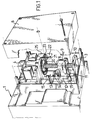
- a power switch is indicated 1
- its operating lever is indicated 2
- the support structure of the remote actuation device applied to the switch is indicated 3
- a cover for the device is indicated 6.
- a motor 4 preferably a direct-current motor, is fixed to a plate 25 rigidly fixed to the structure 3 and is coupled to a lead screw transmission member.
- the shaft 7 of the motor is axially coupled to a screw 8, the ends of which are supported on the structure 3 by bearings 5, 10, in particular thrust bearings, and the screw 8 is coupled with a recirculating-ball nut 9.
- a slider 11 is coupled to the nut 9 for translation and slides along a pair of guides 12 formed in the support structure 3 parallel to the axis of the screw 8 and to the direction in which the switch lever 2 moves to pass from its open to its closed position and vice versa.
- the slider 11 has a slot 13 with a pair of pins 14 between which the lever 2 of the switch is inserted.
- Two microswitches (shown only in Figure 1) are arranged at the upper and lower ends of one of the guides 12 to stop the motor 4 when they are engaged by the slider 11 in its travel-limit positions along the guides 12.
- a direct current motor is chosen as the motor 4 because of its rapid response and the high torque which characterises this type of motor.
- the recirculating-ball actuator provides an extremely compact device which is able to operate a switch remotely with a switching time of less than 100 milliseconds (in one actual case, a few tens of milliseconds).
- the device is put into operation by the insertion of the operating lever 2 in the slot 13 in the slider 11 in such a way that the lever itself is between the pins 14 and then fixing the support structure 3 to the body of the switch with appropriate fixing means, not shown.
- the device is ready for operation. It is supposed, for example, that the device is in the position shown in the drawings. Operation of the motor 4 rotates the screw 8 which causes the nut 9 to move upwards, carrying with it the slider 11 which in turn slides along the guides 12. The lever 2 is then engaged by the lower pin 14 and urged upwards.
- the pins 14 are mounted idly on the slider and their presence serves to avoid friction between the lever and the slider, due to the fact that the latter has a rectilinear movement while the lever moves through an arc and there is thus relative movement between them.
- the pins are not indispensable: in some cases direct engagement of the lever in the slider slot may be acceptable.
- Reverse operation of the motor returns the nut downwards, returning the slider, and therefore the lever 2 of the switch, to its starting position.
- an externally-operable mechanism is provided to act on the screw 8.
- This mechanism includes a first bevel gear 20 securely fixed to the screw 8 and a second, smaller bevel gear 21 mounted on an arm 22 securely fixed to the plate 25 so as to be rotatable in mesh with the first gear 20.
- the second gear has a central hexagonal hole 23 into which a key with a corresponding hexagonal section may be inserted from outside the device to enable it to be operated.
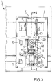
- the actuator device includes a box structure 31 with an attachment 32 for fitting to an "OMEGA" guide, that is a guide defined by European Standards EN50022 and EN50023, and with means, not shown, for coupling to a switch mounted in a box structure similar in shape to the box structure 31 of the device.
- an actuator which includes a motor 33, preferably a direct current motor, the shaft of which is fixed for rotation with a screw 34 along which moves a recirculating-ball nut 35.
- a rack 36 is fixed to the nut 35 and moves, when the motor 33 is operated in one sense or the other, into one or the other of the two travel-limit positions shown in Figure 4 and Figure 5 respectively.
- the rack 36 engages the teeth of a gear 37 mounted idly on a shaft 38 fixed to the body 31.
- the gear has an arcuate slot 39 in which slides a shaft 40 fixed to a lever 41 pivoted on the shaft 38 and engaging, at its opposite end, the lever, indicated 42, of the switch to be actuated.
- a spiral spring returns the gear 37 to its starting position when it is free of the rack.
- the travel of the rack 36 is longer than the length of the rack itself so that it engages the gear only in one portion of its path, freeing itself at the end of its travel so as to free the gear which is thus returned to its starting position by the spring.
- the motor 33 is operated to rotate the screw 34 which causes the nut 35 to move upwards.
- the rack 36 moves with the nut and, after a brief distance of free travel, engages the teeth of the gear 37 causing it to rotate clockwise.
- the motor is preferably stopped by means of microswitches or the like, not shown in the drawings, operated by the rack when it reaches its travel limits.
- This embodiment has provided a remote-actuation device which is made up of few parts, which may be made in inexpensive material, for example moulded plastics, which is easy to assemble and which may be applied to the "OMEGA" guide of an ordinary electrical panel.
Landscapes
- Transmission Devices (AREA)
Applications Claiming Priority (4)
| Application Number | Priority Date | Filing Date | Title |
|---|---|---|---|
| ITMI930417 | 1993-03-04 | ||
| ITMI930418 | 1993-05-19 | ||
| IT93MI000417U IT229921Y1 (it) | 1993-05-19 | 1993-05-19 | Dispositivo per l'azionamento a distanza di un interruttore elettrico in particolare di un interruttore di potenza |
| IT93MI000418U IT229922Y1 (it) | 1993-05-19 | 1993-05-19 | Dispositivo di comando a distanza di un interruttore elettrico |
Publications (2)
| Publication Number | Publication Date |
|---|---|
| EP0625788A2 true EP0625788A2 (fr) | 1994-11-23 |
| EP0625788A3 EP0625788A3 (fr) | 1995-10-25 |
Family
ID=26330959
Family Applications (1)
| Application Number | Title | Priority Date | Filing Date |
|---|---|---|---|
| EP94201358A Withdrawn EP0625788A3 (fr) | 1993-05-19 | 1994-05-13 | Dispsositif pour la commande à distance d'un commutateur électrique. |
Country Status (1)
| Country | Link |
|---|---|
| EP (1) | EP0625788A3 (fr) |
Cited By (1)
| Publication number | Priority date | Publication date | Assignee | Title |
|---|---|---|---|---|
| WO2014020287A1 (fr) * | 2012-08-02 | 2014-02-06 | Hager-Electro Sas | Appareil actionneur de type auxiliaire d'un appareil electrique de protection de ligne |
Family Cites Families (4)
| Publication number | Priority date | Publication date | Assignee | Title |
|---|---|---|---|---|
| NL300256A (fr) * | 1962-11-08 | |||
| US3296565A (en) * | 1965-01-06 | 1967-01-03 | Gen Electric | Motor-driven switch operating mechanism with indicating means |
| DE1690093B1 (de) * | 1967-11-24 | 1971-10-14 | Siemens Ag | Motorantrieb fuer elektrische schalter mit einer auf einer spindel laufenden wandermutter |
| GB1443002A (en) * | 1973-05-04 | 1976-07-21 | Dorman Smith Switchgear Ltd | Mounting electrical components |
-
1994
- 1994-05-13 EP EP94201358A patent/EP0625788A3/fr not_active Withdrawn
Cited By (4)
| Publication number | Priority date | Publication date | Assignee | Title |
|---|---|---|---|---|
| WO2014020287A1 (fr) * | 2012-08-02 | 2014-02-06 | Hager-Electro Sas | Appareil actionneur de type auxiliaire d'un appareil electrique de protection de ligne |
| FR2994330A1 (fr) * | 2012-08-02 | 2014-02-07 | Hager Electro Sas | Appareil actionneur de type auxiliaire d'un appareil de protection de ligne |
| CN104508788A (zh) * | 2012-08-02 | 2015-04-08 | 黑格电子股份有限公司 | 用于保护线路的电气装置的辅助致动装置 |
| CN104508788B (zh) * | 2012-08-02 | 2017-05-31 | 黑格电子股份有限公司 | 用于保护线路的电气装置的辅助致动装置 |
Also Published As
| Publication number | Publication date |
|---|---|
| EP0625788A3 (fr) | 1995-10-25 |
Similar Documents
| Publication | Publication Date | Title |
|---|---|---|
| US5838219A (en) | Electrical circuit breaker with manual and remote actuators | |
| US4804809A (en) | Motor operator for padmount switchgear | |
| KR101690129B1 (ko) | 스위치기어용 개폐기 조작장치 | |
| US20180123327A1 (en) | Method and apparatus for translating coupling features of a plug-in unit | |
| US5299678A (en) | Limit switch mechanism for garage door opener | |
| CN102543551A (zh) | 一种三工位开关的操作机构 | |
| KR102635877B1 (ko) | 바이스테이블 릴레이를 위한 기계식 작동 어셈블리 및 바이스테이블 릴레이 어셈블리 | |
| EP0864720B1 (fr) | Transmission par chaíne | |
| EP0625788A2 (fr) | Dispsositif pour la commande à distance d'un commutateur électrique | |
| CN109243928B (zh) | 机构嵌入式塑壳断路器 | |
| CN218351397U (zh) | 一种适用于断路器的驱动装置 | |
| CN209561232U (zh) | 一种塑壳断路器机械连锁机构 | |
| CN110021494A (zh) | 用于开关柜中接地开关的传动系统以及开关柜 | |
| CN220306194U (zh) | 一种电动、手动一体化操作机构及抽屉单元断路器 | |
| US3394616A (en) | Electric switch operating apparatus | |
| CN110931320B (zh) | 一种断路器分合闸装置 | |
| CN212676201U (zh) | 一种双电源操作机构 | |
| CN109038340A (zh) | 用于断路器的手电动分合闸操作机构 | |
| CN223261133U (zh) | 一种抽屉联动结构 | |
| CN208862455U (zh) | 用于断路器的手电动分合闸操作机构 | |
| EP0936380B1 (fr) | Actuateur linéaire | |
| CN222749389U (zh) | 用于自动转换开关系统的连锁机构及开关系统 | |
| CN219476561U (zh) | 一种侧面操作的隔离开关 | |
| CN222146011U (zh) | 一种高压大电流的选相合闸装置 | |
| CN222562476U (zh) | 单线圈电磁式电动操作装置 |
Legal Events
| Date | Code | Title | Description |
|---|---|---|---|
| PUAI | Public reference made under article 153(3) epc to a published international application that has entered the european phase |
Free format text: ORIGINAL CODE: 0009012 |
|
| AK | Designated contracting states |
Kind code of ref document: A2 Designated state(s): BE DE ES FR IT |
|
| RAX | Requested extension states of the european patent have changed |
Free format text: SI |
|
| RBV | Designated contracting states (corrected) |
Designated state(s): BE DE ES FR IT |
|
| PUAL | Search report despatched |
Free format text: ORIGINAL CODE: 0009013 |
|
| AK | Designated contracting states |
Kind code of ref document: A3 Designated state(s): BE DE ES FR IT |
|
| STAA | Information on the status of an ep patent application or granted ep patent |
Free format text: STATUS: THE APPLICATION IS DEEMED TO BE WITHDRAWN |
|
| 18D | Application deemed to be withdrawn |
Effective date: 19960426 |