EP0626151A2 - Appareil de compression pour provoquer un état exsangue dans les extrémités - Google Patents
Appareil de compression pour provoquer un état exsangue dans les extrémités Download PDFInfo
- Publication number
- EP0626151A2 EP0626151A2 EP94107466A EP94107466A EP0626151A2 EP 0626151 A2 EP0626151 A2 EP 0626151A2 EP 94107466 A EP94107466 A EP 94107466A EP 94107466 A EP94107466 A EP 94107466A EP 0626151 A2 EP0626151 A2 EP 0626151A2
- Authority
- EP
- European Patent Office
- Prior art keywords
- pressure
- compression
- blood pressure
- value
- control
- Prior art date
- Legal status (The legal status is an assumption and is not a legal conclusion. Google has not performed a legal analysis and makes no representation as to the accuracy of the status listed.)
- Granted
Links
Images
Classifications
-
- A—HUMAN NECESSITIES
- A61—MEDICAL OR VETERINARY SCIENCE; HYGIENE
- A61B—DIAGNOSIS; SURGERY; IDENTIFICATION
- A61B17/00—Surgical instruments, devices or methods
- A61B17/12—Surgical instruments, devices or methods for ligaturing or otherwise compressing tubular parts of the body, e.g. blood vessels or umbilical cord
- A61B17/132—Tourniquets
- A61B17/135—Tourniquets inflatable
- A61B17/1355—Automated control means therefor
Definitions
- the invention relates to a compression apparatus for producing an artificial void on extremities during surgical interventions or for intravenous local anesthesia, with a compression cuff which can be placed on the extremities and acted upon by a pressure medium, and with a controllable pressure control valve for the pressure medium for setting the compression pressure in the compression cuff.
- Compression devices of this type are known from medical practice and are used to create a bloodless area during surgical interventions on the upper or lower extremities and, using a so-called double-chamber cuff, also for intravenous use Local anesthesia.
- the compression pressure distal to the compression cuff ensures that the blood is empty for the duration of the operation.
- the size of the compression pressure is determined within the scope of a discretion, which can be associated with the disadvantage that an excessive compression pressure u. U. can lead to lesions, pressure paralysis or late effects on the limb in question.
- the invention is based on the object of designing a compression apparatus of the type mentioned at the outset in such a way that permissible values for the compression pressure and consequential damage in the form of lesions or pressure paralysis are avoided.
- a compression apparatus which solves this problem is characterized according to the invention by the features mentioned at the outset in combination with an automatic blood pressure measuring device and a control signal generator which generates a control signal for the control of the pressure control valve which is dependent on the measured value of the blood pressure determined at regular or regular intervals, so that the pressure control valve Compression pressure in the compression cuff changes accordingly when the blood pressure measurement changes.
- the invention is based on the idea of automatically adapting the compression pressure to blood pressure values that change during the operation; If the patient's permanently measured blood pressure rises or falls during the operation, the measured values also change accordingly the respective compression pressure in the cuff, with the result that compression pressures which are too high and consequential damage associated with them can no longer occur.
- the blood pressure value is converted into the control signal for the pressure control valve in such a way that the compression pressure in the compression cuff is equal to the currently measured blood pressure, increased by a predeterminable additional pressure.
- the additional pressure expediently has a constant variable that is independent of the blood pressure currently measured; however, it is of course also within the scope of the invention to select the additional pressure as a function of the currently measured blood pressure.
- the blood pressure value can be converted into the control signal for the pressure regulating valve in various ways.
- the control signal generator is preferably integrated in a computer-assisted control unit which has an arithmetic unit for determining the control signal size from the size of the blood pressure measurement value.
- An embodiment of the invention which is particularly preferred in this context is characterized in that a compression pressure sensor Pressure sensor is provided which causes the compression cuff to switch to the manually controlled pressure control valve as soon as or as long as the compression pressure (actual value) measured by the pressure sensor deviates from the compression pressure (target value) determined from the blood pressure measurement values and / or actuates an alarm transmitter.
- the actual value and the desired value are expediently compared in the control unit, which switches the two-way valve via a switching line as soon as the actual value deviates from the desired value beyond a predeterminable, narrow tolerance range.
- control device has display devices for the blood pressure measurement value, the additional pressure and / or the setpoint value of the compression pressure and data input devices for the size of the additional pressure. It is also advisable to provide a pressure gauge that shows the compression pressure (actual value) on the compression sleeve.
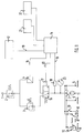
- the compression apparatus shown in FIG. 1 becomes, for example, a central one at a suitable pressure medium supply, not shown Compressed air supply network, a compressor or a compressed gas, in particular CO2 bottle with pressure reducing valve connected.
- a pressure reducer 2 reduces the supply pressure to values suitable for the compression apparatus, for example between two and five bar.
- a further pressure reduction takes place in continuously adjustable pressure control valves 3, 4, the output pressure of which, depending on the setting or control, can be between 0 and 700 mm Hg.
- a compression sleeve which in turn is not shown, can be connected, as described, for example, in DE 33 33 311 C2.
- connection 5 is provided up to a maximum pressure of 700 mm Hg, so that the compression sleeve has to be connected here if it is to be applied to the lower extremities.
- the other connection 6 is limited in pressure to 400 mm Hg, so that it serves as a connection for a compression sleeve placed on the upper extremities.
- the mechanical switch 7 can be used to switch between the connections 5, 6.
- a so-called double-chamber cuff can be connected, which is used in a known manner for intravenous local anesthesia.
- Such double-chamber cuffs have a proximal and a distal pressure chamber.
- a separate connection 8 ', 9' (distal) or 8 '', 9 '' (proximal) is provided for each of these pressure chambers; and these connections are in turn designed for ranges up to 700 mm Hg 8 ', 8''or 400 mm Hg 9', 9 '' with regard to the maximum compression pressure and by mechanical changeover switches which, like the switches 7, are actuated by a handle 11, on, off and / or switchable.
- an automatic blood pressure monitor is referred to measures the patient's blood pressure permanently or at regular intervals, approximately every 3-5 minutes.
- the measured value corresponding to the size of the blood pressure is fed via a line 13 to a control unit 14, in which there is a control signal generator (not shown in detail) which generates a control signal for the control of the pressure control valve 4 which is dependent on the measured value of the blood pressure supplied, this control signal via the Line 15 is fed to the control input of the pressure control valve 4.
- a control signal generator (not shown in detail) which generates a control signal for the control of the pressure control valve 4 which is dependent on the measured value of the blood pressure supplied
- this control signal via the Line 15 is fed to the control input of the pressure control valve 4.
- it is an electronically controllable pressure regulating valve 4, to which an electrical control signal generated by the control signal generator is fed accordingly.
- This blood pressure-dependent control of the pressure control valve 4 has the result that the compression pressure in the compression cuff changes accordingly when the blood pressure measurement value changes. If the patient's blood pressure rises, the compression pressure increases and vice versa.
- the blood pressure measurement value 12 can be converted into the control signal for the pressure control valve 4 in such a way that the compression pressure in the compression cuff is equal to the currently measured blood pressure, increased by a predeterminable additional pressure, so that the compression pressure always exceeds the fixed amount of the additional pressure the currently measured blood pressure.
- the control unit 14 contains an arithmetic unit, also not shown in detail, which determines the control signal size from the size of the blood pressure value.
- a manually adjustable, mechanical pressure control valve 3 is additionally provided.
- the compression sleeve can be switched between two pressure control valves 3, 4 by means of a magnetic drive 17 by means of a two-way valve 16.
- the compression pressure on the compression cuff is detected by a pressure sensor 18, which causes the compression cuff to switch over to the manually controlled pressure control valve 3 when the compression pressure measured by the pressure sensor 18 as the actual value deviates from the compression pressure determined from the blood pressure measurement values as the desired value.
- the output of the pressure sensor 18 and the control input of the two-way valve 16 are connected to the control device 14 via lines 19, 20.
- the comparison of the actual value and the setpoint value of the compression pressure takes place in the control unit 14, which switches the two-way valve 16 via the switching line 20 if the actual value and the setpoint value differ from one another or at least actuates an alarm device.
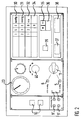
- control device 14 is equipped with display devices 21 for the blood pressure measurement value, the additional pressure, the setpoint value of the compression pressure, etc.
- data input devices 22 are provided with which u. a. the size of the additional pressure can be entered.
- a manometer indicating the compression pressure (actual value) on the compression sleeve is designated by 23.
- the pressure control is carried out by the control device 14 in such a way that when the compression apparatus is switched on, the value of the predetermined additional pressure is added to the measured systolic blood pressure value and the total pressure resulting from this sum is used as the setpoint for the compression pressure. If necessary, the values of the Additional pressure can be varied up or down by manual input.
- the control unit 14 takes over the electronic monitoring of all relevant parameters; in the event of an error, an optical and acoustic alarm is triggered and a code number appears in an error display field 34 (FIG. 2), from which the type of error can be seen.
- the mechanical pressure control valve 3 which is mandatory before the automatic operation of the compression apparatus.
- the two-way valve 16 is connected in such a way that in the event of a failure of the control unit 14, in particular also in the event of a power failure, the pressure control valve 3, which can be set manually, is switched over.
- This compression pressure is the setpoint value according to which the control unit 14 controls the pressure control valve 4 via the line 15.
- the two-way valve 16 is still in the position shown in FIG. 1 from the switch-on process, that is to say connects the compression sleeve to the pressure medium supply via the manually adjustable pressure control valve 3.
- the actual value of the compression pressure detected by the pressure sensor 18 generally initially deviates from that for the control of the pressure control valve 4 from the desired value, so that the two-way valve 16 initially remains in the starting position according to FIG. 1.
- This deviation of the actual value from the target value is shown in the display field 34 as an error, for example with the number "2" if the pressure is too low, with the number "3" if the pressure is too high.
- the actual value of the compression pressure is set to the desired value by actuating the handle 40 of the pressure control valve 3, which can be seen from the fact that the error display in the display field 34 goes out.
- the pressure actual value set in this way which can be read on the manometer 23, corresponds essentially to the average compression pressure by which the compression pressure is controlled in blood pressure-dependent manner in the automatic operation of the compression apparatus.
- This automatic pressure control is switched on with key 37 "Start” and acknowledged with key 36.
- the two-way valve 16 switches over to the automatically controlled pressure control valve 4, so that the compression pressure is now controlled automatically as a function of the systolic blood pressure.
- the systolic blood pressure is now shown in the display field 30, the setpoint value of the compression pressure in the display field 31, the compression time in the display field 32 and a possible one in the display field 34 Error.
- This operating state is the basis for the display and input devices of FIG. 2.
- the button 38 "Stop" is actuated and acknowledged with the button 36.
- the two-way valve 16 then switches back to the state shown in FIG. 1 and the compression pressure on the compression sleeve corresponds to the compression pressure set on the manually operated pressure control valve 3. It can now be slowly reset to zero by actuating the handle 40 of the pressure control valve 3. If the electronics fail, the device can be switched off at the power switch 39. Even then, the compression pressure on the compression sleeve corresponds to the value set on the manually operated pressure control valve 3.
Landscapes
- Health & Medical Sciences (AREA)
- Life Sciences & Earth Sciences (AREA)
- Surgery (AREA)
- Molecular Biology (AREA)
- General Health & Medical Sciences (AREA)
- Vascular Medicine (AREA)
- Nuclear Medicine, Radiotherapy & Molecular Imaging (AREA)
- Hematology (AREA)
- Engineering & Computer Science (AREA)
- Biomedical Technology (AREA)
- Heart & Thoracic Surgery (AREA)
- Medical Informatics (AREA)
- Biophysics (AREA)
- Animal Behavior & Ethology (AREA)
- Reproductive Health (AREA)
- Public Health (AREA)
- Veterinary Medicine (AREA)
- Measuring Pulse, Heart Rate, Blood Pressure Or Blood Flow (AREA)
- Surgical Instruments (AREA)
- Measurement And Recording Of Electrical Phenomena And Electrical Characteristics Of The Living Body (AREA)
- Electrotherapy Devices (AREA)
- Medicines Containing Material From Animals Or Micro-Organisms (AREA)
- Prostheses (AREA)
- Silicates, Zeolites, And Molecular Sieves (AREA)
- Eye Examination Apparatus (AREA)
Applications Claiming Priority (2)
| Application Number | Priority Date | Filing Date | Title |
|---|---|---|---|
| DE4317600 | 1993-05-27 | ||
| DE4317600A DE4317600C2 (de) | 1993-05-27 | 1993-05-27 | Kompressionsapparat zur Herstellung einer künstlichen Blutleere an Extremitäten |
Publications (3)
| Publication Number | Publication Date |
|---|---|
| EP0626151A2 true EP0626151A2 (fr) | 1994-11-30 |
| EP0626151A3 EP0626151A3 (fr) | 1995-03-15 |
| EP0626151B1 EP0626151B1 (fr) | 1997-09-10 |
Family
ID=6489011
Family Applications (1)
| Application Number | Title | Priority Date | Filing Date |
|---|---|---|---|
| EP94107466A Expired - Lifetime EP0626151B1 (fr) | 1993-05-27 | 1994-05-13 | Appareil de compression pour provoquer un état exsangue dans les extrémités |
Country Status (5)
| Country | Link |
|---|---|
| US (1) | US5569304A (fr) |
| EP (1) | EP0626151B1 (fr) |
| JP (1) | JPH0751276A (fr) |
| AT (1) | ATE157850T1 (fr) |
| DE (2) | DE4317600C2 (fr) |
Cited By (1)
| Publication number | Priority date | Publication date | Assignee | Title |
|---|---|---|---|---|
| DE102007054494A1 (de) | 2007-11-13 | 2009-05-20 | Ulrich Gmbh & Co. Kg | Kompressionsgerät zur Herstellung einer künstlichen Blutleere und Verfahren zur Steuerung des Kompressionsgeräts |
Families Citing this family (25)
| Publication number | Priority date | Publication date | Assignee | Title |
|---|---|---|---|---|
| JPH10260131A (ja) * | 1997-03-19 | 1998-09-29 | Seitai Hikarijoho Kenkyusho:Kk | 光計測装置 |
| DE29711255U1 (de) * | 1997-06-27 | 1997-09-18 | MIPM Mammendorfer Institut für Physik und Medizin GmbH, 82285 Hattenhofen | Vorrichtung zum vorübergehenden Abdrücken eines Blutgefäßes |
| US6213939B1 (en) * | 1998-12-10 | 2001-04-10 | Mcewen James Allen | Hazard monitor for surgical tourniquet systems |
| US6336216B1 (en) | 1998-12-10 | 2002-01-01 | International Business Machines Corporation | Objects oriented programming system with objects for storing compressed data files and self-extracting the data files |
| DE10007231A1 (de) * | 2000-02-17 | 2001-08-30 | Jakub Mach | Venenstaugerät |
| DE102006016848B4 (de) * | 2006-04-07 | 2012-05-24 | W. Krömker GmbH | Vorrichtung zum Ausüben eines kontinuierlichen Drucks auf eine im Einstichbereich eines Katheters anlegbare Druckmanschette zur invasiven Blutdruckmessung |
| US7717855B2 (en) | 2006-12-06 | 2010-05-18 | The Hospital For Sick Children | System for performing remote ischemic preconditioning |
| US8048105B2 (en) * | 2007-04-19 | 2011-11-01 | Western Clinical Engineering Ltd. | Adaptive surgical tourniquet apparatus and method |
| US8425426B2 (en) | 2007-11-09 | 2013-04-23 | Western Clinical Engineering, Ltd | Tourniquet apparatus for measuring limb occlusion pressure |
| US8083763B2 (en) * | 2009-02-10 | 2011-12-27 | Western Clinical Engineering Ltd. | Apparatus and method for estimating leakage in a surgical tourniquet system |
| US9113895B2 (en) * | 2009-02-19 | 2015-08-25 | Western Clinical Engineering Ltd. | Integrated tourniquet system |
| ES2431013T3 (es) * | 2009-05-13 | 2013-11-22 | The Hospital For Sick Children | Potenciación del rendimiento |
| KR20120139723A (ko) * | 2010-02-01 | 2012-12-27 | 더 호스피탈 포 식 칠드런 | 재발협착증의 치료 및 예방을 위한 원격 허혈 처치 |
| CA2795053A1 (fr) | 2010-03-31 | 2011-10-06 | The Hospital For Sick Children | Utilisation de conditionnement ischemique a distance pour ameliorer l'evolution apres un infarctus du myocarde |
| SG10201908576VA (en) | 2010-04-08 | 2019-10-30 | Hospital For Sick Children | Use of remote ischemic conditioning for traumatic injury |
| SE535901C2 (sv) | 2010-06-07 | 2013-02-12 | St Jude Medical Systems Ab | Femoralt kompressionssystem och metod för att åstadkomma kompression med det femorala kompressionssystemet |
| JP5763386B2 (ja) * | 2011-03-31 | 2015-08-12 | テルモ株式会社 | 肢部圧迫装置 |
| US8764789B2 (en) | 2011-04-15 | 2014-07-01 | CellAegis Devices Inc. | System for performing remote ischemic conditioning |
| USD708338S1 (en) | 2012-08-15 | 2014-07-01 | CellAegis Devices Inc. | Cuff for remote ischemic conditioning |
| WO2014199239A2 (fr) | 2013-03-15 | 2014-12-18 | The Hospital For Sick Children | Méthodes se rapportant à l'utilisation du conditionnement ischémique à distance |
| CA2942614A1 (fr) | 2013-03-15 | 2014-10-16 | The Hospital For Sick Children | Procedes pour moduler une autophagie en utilisant un conditionnement ischemique a distance |
| WO2014140832A2 (fr) | 2013-03-15 | 2014-09-18 | The Hospital For Sick Children | Traitement d'un dysfonctionnement érectile au moyen d'un conditionnement ischémique à distance |
| AU2013203746B2 (en) * | 2013-03-15 | 2015-05-07 | Cellaegis Devices, Inc. | Gas Powered System for Performing Remote Ischemic Conditioning |
| US20210068843A1 (en) * | 2018-05-10 | 2021-03-11 | Techno Science Co., Ltd. | Hemostasis aid and tourniquet |
| US12611512B2 (en) * | 2020-06-12 | 2026-04-28 | Becton, Dickinson And Company | Catheter placement device and related methods |
Family Cites Families (14)
| Publication number | Priority date | Publication date | Assignee | Title |
|---|---|---|---|---|
| US2614565A (en) * | 1951-05-17 | 1952-10-21 | John K Packer | Automatic tourniquet |
| US4321919A (en) * | 1979-12-11 | 1982-03-30 | Leukocyte Research, Inc. | Method and system for externally treating human blood |
| US4479494A (en) * | 1982-01-05 | 1984-10-30 | Western Clinical Engineering Ltd. | Adaptive pneumatic tourniquet |
| US4520819A (en) * | 1983-04-15 | 1985-06-04 | Aspen Laboratories, Inc. | Tourniquet with differential pressure occlusion detector |
| DE3333311A1 (de) * | 1983-09-15 | 1985-04-04 | Fa. Heinrich C. Ulrich, 7900 Ulm | Blutleere-manschette fuer blutleere-geraete |
| US4605010A (en) * | 1984-05-17 | 1986-08-12 | Western Clinical Engineering Ltd. | Pressurizing cuff |
| US4671290A (en) * | 1985-01-15 | 1987-06-09 | Richards Medical Company | Automatic tourniquet |
| US4770175A (en) * | 1986-10-22 | 1988-09-13 | Western Clinical Engineering Ltd. | Occlusive cuff |
| US5048536A (en) * | 1987-04-03 | 1991-09-17 | Mcewen James A | Tourniquet for regulating applied pressures |
| US5181522A (en) * | 1987-04-03 | 1993-01-26 | Abatis Medical Technologies Limited | Tourniquet for sensing and regulation of applied pressure |
| ATA162287A (de) * | 1987-06-26 | 1990-04-15 | Siemens Ag Oesterreich | Vorrichtung zur blutsperre einer koerperextremitaet |
| EP0462088B1 (fr) * | 1990-06-11 | 1995-11-08 | Radi Medical Systems Ab | Dispositif de compression du fémur |
| US5112347A (en) * | 1991-05-14 | 1992-05-12 | Taheri Syde A | Embolectomy catheter, and method of operating same |
| US5383893A (en) * | 1991-11-29 | 1995-01-24 | Daneshvar; Yousef | Device for preventing post-catherization wound bleeding |
-
1993
- 1993-05-27 DE DE4317600A patent/DE4317600C2/de not_active Expired - Fee Related
-
1994
- 1994-05-13 US US08/242,734 patent/US5569304A/en not_active Expired - Lifetime
- 1994-05-13 DE DE59404001T patent/DE59404001D1/de not_active Expired - Lifetime
- 1994-05-13 EP EP94107466A patent/EP0626151B1/fr not_active Expired - Lifetime
- 1994-05-13 AT AT94107466T patent/ATE157850T1/de active
- 1994-05-26 JP JP6112996A patent/JPH0751276A/ja active Pending
Cited By (1)
| Publication number | Priority date | Publication date | Assignee | Title |
|---|---|---|---|---|
| DE102007054494A1 (de) | 2007-11-13 | 2009-05-20 | Ulrich Gmbh & Co. Kg | Kompressionsgerät zur Herstellung einer künstlichen Blutleere und Verfahren zur Steuerung des Kompressionsgeräts |
Also Published As
| Publication number | Publication date |
|---|---|
| US5569304A (en) | 1996-10-29 |
| ATE157850T1 (de) | 1997-09-15 |
| JPH0751276A (ja) | 1995-02-28 |
| EP0626151A3 (fr) | 1995-03-15 |
| DE4317600C2 (de) | 1995-07-13 |
| DE4317600A1 (de) | 1994-12-01 |
| EP0626151B1 (fr) | 1997-09-10 |
| DE59404001D1 (de) | 1997-10-16 |
Similar Documents
| Publication | Publication Date | Title |
|---|---|---|
| EP0626151B1 (fr) | Appareil de compression pour provoquer un état exsangue dans les extrémités | |
| DE3650457T2 (de) | Steuergerät | |
| EP0285962B1 (fr) | Circuit de contrôle pour un appareil chirurgical à haute fréquence | |
| EP0359760B1 (fr) | Dispositif de controle de charges s'exercant sur des parties du corps | |
| DE3143421C2 (de) | Laser-Skalpell | |
| DE69927049T2 (de) | Risikowachsystem für chirurgische aderpresssysteme | |
| EP0653192B1 (fr) | Appareil chirurgical à haute fréquence pour couper et/ou coaguler les tissus biologiques | |
| DE69413680T2 (de) | Automatische blutsperrmanschette | |
| DE19510707A1 (de) | Verfahren und Vorrichtung zur Reinhaltung eines medizinischen Instruments | |
| DE4240758A1 (fr) | ||
| EP0316593A1 (fr) | Dispositif d'insufflation pour les interventions endoscopiques | |
| DE3045996A1 (de) | Elektro-chirurgiegeraet | |
| DE19510712A1 (de) | Verfahren und Vorrichtung zur Einleitung eines Gases | |
| DE1061480B (de) | Vorrichtung zur selbsttaetigen Blutdruckueberwachung | |
| EP1125554B1 (fr) | Appareil d'occlusion veineuse | |
| DE3000218C2 (de) | Apparat zum Insufflieren von strömungsfähigen Medien | |
| EP2621421A1 (fr) | Dispositif de chirurgie oculaire | |
| DE69410950T2 (de) | Narkosemittelverdunster | |
| EP3334359A1 (fr) | Procédé et dispositif pour commander l'alimentation en énergie d'un instrument médical | |
| EP0296635A2 (fr) | Procédé pour le fonctionnement d'un tourniquet | |
| EP0266451B1 (fr) | Instrument de réduction d'une pression intraoculaire | |
| DE102007054494B4 (de) | Kompressionsgerät zur Herstellung einer künstlichen Blutleere und Verfahren zur Steuerung des Kompressionsgeräts | |
| DE4339876A1 (de) | Vorrichtung zum Insufflieren | |
| DE4016018C1 (en) | Process regulating circuitry using two measurers in parallel - has range selection stage cooperating with proportional member and lowest and highest value limiting stages | |
| EP3478231A1 (fr) | Dispositif pour délivrer des impulsions d'air comprimé pour un instrument ophtalmologique et procédé de commande pour un tel dispositif |
Legal Events
| Date | Code | Title | Description |
|---|---|---|---|
| PUAI | Public reference made under article 153(3) epc to a published international application that has entered the european phase |
Free format text: ORIGINAL CODE: 0009012 |
|
| AK | Designated contracting states |
Kind code of ref document: A2 Designated state(s): AT BE CH DE FR GB IT LI NL |
|
| PUAL | Search report despatched |
Free format text: ORIGINAL CODE: 0009013 |
|
| AK | Designated contracting states |
Kind code of ref document: A3 Designated state(s): AT BE CH DE FR GB IT LI NL |
|
| RHK1 | Main classification (correction) |
Ipc: A61B 17/12 |
|
| 17P | Request for examination filed |
Effective date: 19950520 |
|
| RAP1 | Party data changed (applicant data changed or rights of an application transferred) |
Owner name: ULRICH, HEINRICH |
|
| GRAG | Despatch of communication of intention to grant |
Free format text: ORIGINAL CODE: EPIDOS AGRA |
|
| GRAH | Despatch of communication of intention to grant a patent |
Free format text: ORIGINAL CODE: EPIDOS IGRA |
|
| 17Q | First examination report despatched |
Effective date: 19970219 |
|
| GRAH | Despatch of communication of intention to grant a patent |
Free format text: ORIGINAL CODE: EPIDOS IGRA |
|
| GRAA | (expected) grant |
Free format text: ORIGINAL CODE: 0009210 |
|
| AK | Designated contracting states |
Kind code of ref document: B1 Designated state(s): AT BE CH DE FR GB IT LI NL |
|
| REF | Corresponds to: |
Ref document number: 157850 Country of ref document: AT Date of ref document: 19970915 Kind code of ref document: T |
|
| REG | Reference to a national code |
Ref country code: CH Ref legal event code: NV Representative=s name: ISLER & PEDRAZZINI AG Ref country code: CH Ref legal event code: EP |
|
| ET | Fr: translation filed | ||
| ITF | It: translation for a ep patent filed | ||
| REF | Corresponds to: |
Ref document number: 59404001 Country of ref document: DE Date of ref document: 19971016 |
|
| GBT | Gb: translation of ep patent filed (gb section 77(6)(a)/1977) |
Effective date: 19980213 |
|
| PLBE | No opposition filed within time limit |
Free format text: ORIGINAL CODE: 0009261 |
|
| STAA | Information on the status of an ep patent application or granted ep patent |
Free format text: STATUS: NO OPPOSITION FILED WITHIN TIME LIMIT |
|
| 26N | No opposition filed | ||
| REG | Reference to a national code |
Ref country code: GB Ref legal event code: IF02 |
|
| REG | Reference to a national code |
Ref country code: CH Ref legal event code: PCAR Free format text: ISLER & PEDRAZZINI AG;POSTFACH 1772;8027 ZUERICH (CH) |
|
| PGFP | Annual fee paid to national office [announced via postgrant information from national office to epo] |
Ref country code: GB Payment date: 20080414 Year of fee payment: 15 |
|
| GBPC | Gb: european patent ceased through non-payment of renewal fee |
Effective date: 20090513 |
|
| PG25 | Lapsed in a contracting state [announced via postgrant information from national office to epo] |
Ref country code: GB Free format text: LAPSE BECAUSE OF NON-PAYMENT OF DUE FEES Effective date: 20090513 |
|
| PGFP | Annual fee paid to national office [announced via postgrant information from national office to epo] |
Ref country code: NL Payment date: 20100304 Year of fee payment: 17 |
|
| PGFP | Annual fee paid to national office [announced via postgrant information from national office to epo] |
Ref country code: BE Payment date: 20100525 Year of fee payment: 17 |
|
| PGFP | Annual fee paid to national office [announced via postgrant information from national office to epo] |
Ref country code: FR Payment date: 20110603 Year of fee payment: 18 Ref country code: CH Payment date: 20110606 Year of fee payment: 18 |
|
| PGFP | Annual fee paid to national office [announced via postgrant information from national office to epo] |
Ref country code: AT Payment date: 20110520 Year of fee payment: 18 |
|
| PGFP | Annual fee paid to national office [announced via postgrant information from national office to epo] |
Ref country code: IT Payment date: 20110527 Year of fee payment: 18 |
|
| BERE | Be: lapsed |
Owner name: *ULRICH HEINRICH Effective date: 20110531 |
|
| REG | Reference to a national code |
Ref country code: NL Ref legal event code: V1 Effective date: 20111201 |
|
| PG25 | Lapsed in a contracting state [announced via postgrant information from national office to epo] |
Ref country code: NL Free format text: LAPSE BECAUSE OF NON-PAYMENT OF DUE FEES Effective date: 20111201 |
|
| PG25 | Lapsed in a contracting state [announced via postgrant information from national office to epo] |
Ref country code: BE Free format text: LAPSE BECAUSE OF NON-PAYMENT OF DUE FEES Effective date: 20110531 |
|
| REG | Reference to a national code |
Ref country code: DE Ref legal event code: R082 Ref document number: 59404001 Country of ref document: DE Representative=s name: HENTRICH, SWEN, DIPL.-PHYS. DR.RER.NAT., DE Effective date: 20120503 Ref country code: DE Ref legal event code: R081 Ref document number: 59404001 Country of ref document: DE Owner name: ULRICH GMBH & CO. KG, DE Free format text: FORMER OWNER: ULRICH, HEINRICH C., 89081 ULM, DE Effective date: 20120503 |
|
| PGFP | Annual fee paid to national office [announced via postgrant information from national office to epo] |
Ref country code: DE Payment date: 20120608 Year of fee payment: 19 |
|
| REG | Reference to a national code |
Ref country code: CH Ref legal event code: PL |
|
| REG | Reference to a national code |
Ref country code: AT Ref legal event code: MM01 Ref document number: 157850 Country of ref document: AT Kind code of ref document: T Effective date: 20120513 |
|
| PG25 | Lapsed in a contracting state [announced via postgrant information from national office to epo] |
Ref country code: AT Free format text: LAPSE BECAUSE OF NON-PAYMENT OF DUE FEES Effective date: 20120513 Ref country code: CH Free format text: LAPSE BECAUSE OF NON-PAYMENT OF DUE FEES Effective date: 20120531 Ref country code: LI Free format text: LAPSE BECAUSE OF NON-PAYMENT OF DUE FEES Effective date: 20120531 |
|
| PG25 | Lapsed in a contracting state [announced via postgrant information from national office to epo] |
Ref country code: IT Free format text: LAPSE BECAUSE OF NON-PAYMENT OF DUE FEES Effective date: 20120513 |
|
| REG | Reference to a national code |
Ref country code: FR Ref legal event code: ST Effective date: 20130131 |
|
| PG25 | Lapsed in a contracting state [announced via postgrant information from national office to epo] |
Ref country code: FR Free format text: LAPSE BECAUSE OF NON-PAYMENT OF DUE FEES Effective date: 20120531 |
|
| PG25 | Lapsed in a contracting state [announced via postgrant information from national office to epo] |
Ref country code: DE Free format text: LAPSE BECAUSE OF NON-PAYMENT OF DUE FEES Effective date: 20131203 |
|
| REG | Reference to a national code |
Ref country code: DE Ref legal event code: R119 Ref document number: 59404001 Country of ref document: DE Effective date: 20131203 |