EP0626311A1 - Dispositif de transport pour paquets - Google Patents
Dispositif de transport pour paquets Download PDFInfo
- Publication number
- EP0626311A1 EP0626311A1 EP94302921A EP94302921A EP0626311A1 EP 0626311 A1 EP0626311 A1 EP 0626311A1 EP 94302921 A EP94302921 A EP 94302921A EP 94302921 A EP94302921 A EP 94302921A EP 0626311 A1 EP0626311 A1 EP 0626311A1
- Authority
- EP
- European Patent Office
- Prior art keywords
- package
- leg
- elongate
- pusher
- frontwardly
- Prior art date
- Legal status (The legal status is an assumption and is not a legal conclusion. Google has not performed a legal analysis and makes no representation as to the accuracy of the status listed.)
- Ceased
Links
- 230000007246 mechanism Effects 0.000 claims abstract description 17
- 229920006302 stretch film Polymers 0.000 claims abstract description 9
- 238000000429 assembly Methods 0.000 description 3
- 238000004806 packaging method and process Methods 0.000 description 1
- 230000000284 resting effect Effects 0.000 description 1
- 239000004753 textile Substances 0.000 description 1
Images


Classifications
-
- B—PERFORMING OPERATIONS; TRANSPORTING
- B65—CONVEYING; PACKING; STORING; HANDLING THIN OR FILAMENTARY MATERIAL
- B65B—MACHINES, APPARATUS OR DEVICES FOR, OR METHODS OF, PACKAGING ARTICLES OR MATERIALS; UNPACKING
- B65B11/00—Wrapping, e.g. partially or wholly enclosing, articles or quantities of material, in strips, sheets or blanks, of flexible material
- B65B11/008—Wrapping, e.g. partially or wholly enclosing, articles or quantities of material, in strips, sheets or blanks, of flexible material by webs revolving around articles moved along the axis of revolution
Definitions
- This invention pertains to a package-conveying apparatus useful with a wrapping machine of a type capable of wrapping a package with stretch film from a roll moving in an annular path.
- a roll of stretch film is driven around a ring structure defining an annular path so that stretch film from the roll is wrapped around a package.
- the package is a relatively short package, such as a carton not substantially longer than the wrapping machine, it is known to wrap the package while the package is resting on a support, such as a bed of rollers within the ring structure.
- the package is a relatively long package, such as one or more pieces of lumber, pipe, or tubing or a roll of textile or carpeting, it is known to wrap the package in a spiral pattern as the package is being conveyed through the wrapping machine, as by an input conveyor, a bed of rollers within the wrapping machine, and an output conveyor.
- a package-conveying apparatus useful with a wrapping machine of a type capable of wrapping a package with stretch film from a roll moving in an annular path comprises:
- the apparatus includes two ledges extending in side-to-side relation to each other.
- the apparatus preferably includes a pair of endless belts extending along the elongate table in side-by-side relation to each other, each having an upper run overlying the elongate table and a lower run underlying the elongate table.
- the means for driving the leg of each package pusher includes a double-acting piston-cylinder mechanism, which is connected operatively between the elongate table and the leg of such package pusher.
- the package pushers are operable in such manner that the leg of one such pusher is driven frontwardly as the leg of the other pusher is driven backwardly.
- the leg of whichever of the package pushers is driven frontwardly at any given time is capable of pushing a package from the at least one endless member onto the at least one elongate ledge, as the same leg is driven from the retracted position to the intermediate position.
- the leg of whichever of the package pushers is driven frontwardly at any given time is capable of pushing a package from the at least one elongate ledge, as the same leg is driven from the intermediate position to the extended position.
- a foot is mounted to the leg of each package pusher so as to be selectively movable between an operative position wherein the foot is capable of engaging a package on the at least one endless member so as to enable the leg of such package pusher to push the package as the leg of such package pusher is driven frontwardly and an inoperative position wherein the foot is disposed so as to clear a package thereon as the leg of such package pusher is driven backwardly.
- the foot may be upwardly pivotable to the operative position and downwardly pivotable to the inoperative position.
- each package pusher includes means for pivoting the foot mounted to the leg of such package pusher selectively between the operative and inoperative positions, such as a double-acting piston-cylinder mechanism connected operatively between the leg of such package pusher and the foot mounted thereto.
- a double-acting piston-cylinder mechanism connected operatively between the leg of such package pusher and the foot mounted thereto.
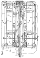
- a package-conveying apparatus 10 constitutes a preferred embodiment of this invention.
- the apparatus 10 comprises an elongate table 12, a pair of elongate ledges 14 extending frontwardly from the table 12, a package conveyor 16 including a pair of endless belts 18 extending along the table 12 in side-by-side relation to each other, and a pair of package pushers 20, in a novel combination operable in a novel manner.
- the apparatus 10 is used with a wrapping machine 22 of the type noted above, such as a Model MSB Mima (trade mark) Stretch Bundler discussed above without a bed of rollers, and with an outfeed conveyor 24 of a known type comprising two endless belts 26.
- the apparatus 10 may be also used with an infeed conveyor (not shown) similar to the outfeed conveyor 24.
- the apparatus 10 is positioned behind the wrapping machine 22 so that the ledges 14 extend frontwardly into the wrapping machine 22, so as to replace the bed of rollers noted above.
- the wrapping machine 22 is capable of wrapping a package, such as the package P shown in broken lines in Figures 1 and 2, with stretch film from a roll 28 moving in an annular path, after the package has been moved onto the elongate ledges 14 extending into the wrapping machine 22. Since the elongate ledges 14 are wrapped along with the package, it becomes necessary to strip the film from the elongate ledges 14, in a manner to be later described. Details of the wrapping machine 22 and details of the outfeed conveyor 24 are outside the scope of this invention and can be readily supplied by persons having ordinary skill in the art.
- Each of the endless belts 18 has an upper run 34 overlying the table 12 and a lower run 36 underlying the table 12.
- the package conveyor 16 is used to convey the package, via the upper runs 34 of the endless belts 18, from a back end 30 of the table 12 to a front end 32 of the table 12.
- one of the package pushers 20 is used to push the package from the upper runs 34 of the endless belts 18 onto the ledges 14, before the package is wrapped with such film.
- the same pusher 20 is used to push the package from the ledges 14 onto the endless belts 26 of the outfeed conveyor 24, after the package has been wrapped with such film.
- the table 12 supports two sub-assemblies 40 in side-by-side relation to each other.
- Each sub-assembly 40 includes one of the elongate ledges 14, one of the endless belts 18, and one of the package pushers 20.
- Each subassembly further includes an electric motor 42 arranged to drive the endless belt 18 of such sub-assembly 40 via a chain drive 44, a package sensor 46 near the back end 30 of the table 12, a package sensor 48 near the front end 32 of the table 12, and a guide rail 50.
- One of the guide rails 50 is shown fragmentarily in Figure 4.
- the package sensors 46, 48 are mechanical sensors of a known type.
- each worm screw 60 has a portion 62 with a right hand thread and a portion 64 with a left hand thread, as viewed from one side of the apparatus 10, namely the side shown in Figure 4.
- the portions 62 with right hand threads are on the same side of the apparatus 10 and mount one such sub-assembly 40.
- the portions 64 with left hand threads are on the other side of the apparatus 10 and mount the other subassembly 40.
- the worm screws 62 are inter-connected via a chain and sprocket drive 66, on one side of the apparatus 10, so as to be conjointly rotatable in either rotatable sense.
- a hand crank 68 is connected to the worm screw 60 near the front end 32 of the table 12. The hand crank 68 enables the worm screws 60 to be manually rotated so as to adjust the sub-assemblies 40 transversely toward and away from each other so as to accommodate packages of various widths.
- the table 12 has a gate assembly 70, which is operable to admit only one package at any one time onto the package conveyor 16 from an infeed conveyor (not shown) similar to the outfeed conveyor 24 and located behind the apparatus 10.
- the gate assembly 70 comprises a transverse roller 72 and a small, double-acting, pneumatic, piston-cylinder mechanism 74 connected operatively between the table 12 and the roller 72.
- the mechanism 74 is operative to raise the roller 72 to an elevated position above the endless belts 18 when it is desired to block a package being conveyed by the infeed conveyor and to lower the roller 72 to a lowered position below the endless belts 18 when it is desired to admit a package onto the package conveyor 16 from the infeed conveyor.
- the roller 72 is shown in the lowered position in Figure 4.
- Each package pusher 20 includes a large, double-acting, pneumatic, piston-cylinder mechanism 80 extending longitudinally for a substantial distance between the table ends 30, 32, as shown schematically in Figures 1 and 2.
- the mechanism 80 comprises an external cylinder 82 mounted fixedly to the elongate table 12 and an internal piston (not shown) arranged to drive an external slider 86 frontwardly and backwardly along the cylinder 82.
- Each package pusher 20 includes a longitudinally extending leg 90, which is mounted to the slider 86 of the piston-cylinder mechanism 80 of such package pusher 20 for conjoint movement with the slider 86 thereof, a foot 92, which is mounted to a front end 94 of the leg 90 so as to be upwardly movable between an operative position and an inoperative position, and a small, double-acting, pneumatic, piston-cylinder mechanism 96, which is connected operatively between the leg 90 and the foot 92.
- the piston-cylinder mechanism 80 of each package pusher 20 is arranged to drive the leg 90 thereof and the foot 92 thereof frontwardly and backwardly.
- One of the piston-cylinder mechanisms 96 is shown in Figure 4.
- the piston-cylinder mechanism 96 of each package pusher 20 is operative to pivot the foot 92 thereof upwardly to the operative position and downwardly to the inoperative position.
- the foot 92 of each package pusher 20 is capable of engaging a package on the upper runs 34 of the endless belts 18 so as to enable the leg 90 of such package pusher 20 to push the package as the leg 90 of such package pusher 20 is driven frontwardly.
- the foot 92 of each package pusher 20 is disposed so as to clear a package on the upper runs 34 of the endless belts 18 as the leg 90 of such package pusher 20 is driven backwardly.
- the package pushers 20 are operable in such manner that the leg 90 of one such pusher 20 is driven frontwardly as the leg 90 of the other pusher 20 is driven backwardly, that the foot 92 of the leg 90 driven frontwardly is pivoted upwardly to the operative position described above, and that the foot 92 of the leg 90 driven backwardly is pivoted downwardly to the inoperative position described above.
- the leg 90 driven frontwardly at any one time is capable of pushing a package from the upper runs 34 of the endless belts 18 onto the elongate ledges 14 as the leg 90 driven frontwardly is driven from the retracted position described above to the intermediate position described above, via the foot 92 on the leg 90 driven frontwardly.
- the leg 90 driven frontwardly at any one time is capable of pushing a package from the elongate ledges 14 onto the outfeed conveyor 24 as the leg 90 driven frontwardly is driven from the intermediate position described above to the extended position described above, because the foot 92 on the leg 90 driven frontwardly is capable of engaging the package, via the foot 92 on the leg 90 driven frontwardly.
- the package and such ledges 14 are wrapped with stretch film from the roll 28. Thereupon, the wrapped package is pushed from the elongate ledges 14, as described above. As the package is pushed from the elongate ledges 14, stretch film wrapping the package and such ledges 14 is stripped from such ledges 14.
Landscapes
- Engineering & Computer Science (AREA)
- Mechanical Engineering (AREA)
- Basic Packing Technique (AREA)
- Attitude Control For Articles On Conveyors (AREA)
- Auxiliary Devices For And Details Of Packaging Control (AREA)
Applications Claiming Priority (2)
| Application Number | Priority Date | Filing Date | Title |
|---|---|---|---|
| US57149 | 1987-06-03 | ||
| US08/057,149 US5305871A (en) | 1993-05-05 | 1993-05-05 | Package-conveying apparatus comprising endless member conveyor and pushers |
Publications (1)
| Publication Number | Publication Date |
|---|---|
| EP0626311A1 true EP0626311A1 (fr) | 1994-11-30 |
Family
ID=22008807
Family Applications (1)
| Application Number | Title | Priority Date | Filing Date |
|---|---|---|---|
| EP94302921A Ceased EP0626311A1 (fr) | 1993-05-05 | 1994-04-25 | Dispositif de transport pour paquets |
Country Status (5)
| Country | Link |
|---|---|
| US (1) | US5305871A (fr) |
| EP (1) | EP0626311A1 (fr) |
| KR (1) | KR0152329B1 (fr) |
| AU (1) | AU654452B1 (fr) |
| CA (1) | CA2120824C (fr) |
Families Citing this family (4)
| Publication number | Priority date | Publication date | Assignee | Title |
|---|---|---|---|---|
| DE59800403D1 (de) * | 1997-03-03 | 2001-02-01 | Gilgen Foerdersysteme Ag Oberw | Fördervorrichtung für regalkanäle von regallageranlagen |
| ES2193798B1 (es) * | 1999-05-06 | 2005-02-16 | Aetna Group, S. P.A. | Dispositivo para el soporte y avance de productos en maquinas para el envolvimiento de los mismos con una pelicula extensible. |
| FI20096129A0 (fi) * | 2009-11-02 | 2009-11-02 | Cross Wrap Oy | Menetelmä ja laite pakattujen paalien valmistamiseksi |
| US20110139582A1 (en) * | 2009-12-15 | 2011-06-16 | Xerox Corporation | System and method for transporting variable-sized media |
Citations (7)
| Publication number | Priority date | Publication date | Assignee | Title |
|---|---|---|---|---|
| DE1291107B (de) * | 1960-04-19 | 1969-03-20 | Lindemann Gmbh Maschinenfabrik | Vorrichtung zum Zufuehren von nach der Methode des Skinpackens mit einer Folie aus Kunststoff zu verpackendem Gut oder von Formwerkzeugen zum Verformen dieser Folie durch Streckziehen |
| GB1487375A (en) * | 1974-09-07 | 1977-09-28 | Mae S | Apparatus for automatic banding of objects |
| US4110957A (en) * | 1975-07-09 | 1978-09-05 | Lancaster William G | Reverse wrap |
| GB2062760A (en) * | 1979-11-10 | 1981-05-28 | Redland Roof Tiles Ltd | Apparatus for the Discontinuous Feed of a Line of Pallets for the Production of Concrete Roofing Tiles |
| US4317322A (en) * | 1980-05-20 | 1982-03-02 | Lantech, Inc. | Rotatable film wrapping apparatus with wrap carrying mechanism |
| US4979358A (en) * | 1989-05-31 | 1990-12-25 | Keip Charles P | Rotary film wrapping apparatus |
| US5027581A (en) * | 1990-05-30 | 1991-07-02 | Hayssen Manufacturing Company | Wrapping method and apparatus |
Family Cites Families (7)
| Publication number | Priority date | Publication date | Assignee | Title |
|---|---|---|---|---|
| US2191743A (en) * | 1938-01-26 | 1940-02-27 | Dorr Co Inc | Classifier mechanism |
| US2461375A (en) * | 1947-04-04 | 1949-02-08 | Eftihios Kosmas | Food refrigerating apparatus |
| US2864303A (en) * | 1950-06-30 | 1958-12-16 | Gen Strapping Corp | Automatic package banding or strapping machine |
| US3191919A (en) * | 1961-06-05 | 1965-06-29 | Sunbeam Equip | Transfer mechanism for heat-treating apparatus |
| US3696944A (en) * | 1970-10-07 | 1972-10-10 | Moore Corp Lee C | Pipe handling apparatus |
| US4178734A (en) * | 1975-07-09 | 1979-12-18 | Lancaster Patrick R | Reverse wrap |
| SE8304084D0 (sv) * | 1983-07-21 | 1983-07-21 | Leng Materialhantering Ab | Sett och anordning for att samlingsforpacka enhetsgods |
-
1993
- 1993-05-05 US US08/057,149 patent/US5305871A/en not_active Expired - Lifetime
-
1994
- 1994-04-07 CA CA002120824A patent/CA2120824C/fr not_active Expired - Fee Related
- 1994-04-20 AU AU60547/94A patent/AU654452B1/en not_active Ceased
- 1994-04-25 EP EP94302921A patent/EP0626311A1/fr not_active Ceased
- 1994-05-03 KR KR1019940009695A patent/KR0152329B1/ko not_active Expired - Fee Related
Patent Citations (7)
| Publication number | Priority date | Publication date | Assignee | Title |
|---|---|---|---|---|
| DE1291107B (de) * | 1960-04-19 | 1969-03-20 | Lindemann Gmbh Maschinenfabrik | Vorrichtung zum Zufuehren von nach der Methode des Skinpackens mit einer Folie aus Kunststoff zu verpackendem Gut oder von Formwerkzeugen zum Verformen dieser Folie durch Streckziehen |
| GB1487375A (en) * | 1974-09-07 | 1977-09-28 | Mae S | Apparatus for automatic banding of objects |
| US4110957A (en) * | 1975-07-09 | 1978-09-05 | Lancaster William G | Reverse wrap |
| GB2062760A (en) * | 1979-11-10 | 1981-05-28 | Redland Roof Tiles Ltd | Apparatus for the Discontinuous Feed of a Line of Pallets for the Production of Concrete Roofing Tiles |
| US4317322A (en) * | 1980-05-20 | 1982-03-02 | Lantech, Inc. | Rotatable film wrapping apparatus with wrap carrying mechanism |
| US4979358A (en) * | 1989-05-31 | 1990-12-25 | Keip Charles P | Rotary film wrapping apparatus |
| US5027581A (en) * | 1990-05-30 | 1991-07-02 | Hayssen Manufacturing Company | Wrapping method and apparatus |
Also Published As
| Publication number | Publication date |
|---|---|
| CA2120824C (fr) | 1998-09-22 |
| US5305871A (en) | 1994-04-26 |
| CA2120824A1 (fr) | 1994-11-06 |
| AU654452B1 (en) | 1994-11-03 |
| KR0152329B1 (ko) | 1998-10-15 |
Similar Documents
| Publication | Publication Date | Title |
|---|---|---|
| US5796052A (en) | Telescopic conveyor for conveying and measuring articles | |
| US4501106A (en) | Wrapping control system for film wrapping machine | |
| US4505092A (en) | Package sensing/film control system for film wrapping machine | |
| US4178740A (en) | Wrapping machine | |
| AU750231B2 (en) | High speed linear bagging machine and method of operation | |
| US4501105A (en) | Film supply monitor for film wrapping machine | |
| CA1203783A (fr) | Emballeuse mecanique de bonbons en forme de batons | |
| US5743071A (en) | Assembly for automatic packaging of series of articles or products delivered on conveyor belts | |
| US2840223A (en) | Article feeding means | |
| US4510731A (en) | Film wrapping machine including film length selection | |
| JP3159989B2 (ja) | 包装袋整理装置 | |
| US6851250B2 (en) | Package wrapping machine with automatic package positioning prior to wrapping | |
| US20060059868A1 (en) | Loader and packaging apparatus | |
| US5305871A (en) | Package-conveying apparatus comprising endless member conveyor and pushers | |
| CN108778933B (zh) | 一种用于移动沿着前进方向不断前进的物品的设备 | |
| EP0092760B1 (fr) | Système de commande d'enveloppement pour une machine d'enveloppement d'un film | |
| US4010595A (en) | Apparatus for supplying boxes to a plurality of filling and weighing stations and removal of filled boxes thereof | |
| US4934621A (en) | Device for continuously feeding a web of material from a stock roll | |
| US2580833A (en) | Packaging machine | |
| US4507904A (en) | Film and package handling apparatus for wrapping machine | |
| JP2742348B2 (ja) | 物品供給コンベヤにおける物品位置決め方法及びその装置 | |
| US6923311B2 (en) | Device to modify the pitch between pushers according to the length of the product | |
| US4527376A (en) | Apparatus for processing box partitions | |
| EP1479608B1 (fr) | Machine pour emballer des objets dans un film rétractable | |
| KR0163051B1 (ko) | 물품포장장치 |
Legal Events
| Date | Code | Title | Description |
|---|---|---|---|
| PUAI | Public reference made under article 153(3) epc to a published international application that has entered the european phase |
Free format text: ORIGINAL CODE: 0009012 |
|
| AK | Designated contracting states |
Kind code of ref document: A1 Designated state(s): DE FR GB NL |
|
| 17P | Request for examination filed |
Effective date: 19950530 |
|
| 17Q | First examination report despatched |
Effective date: 19960703 |
|
| GRAG | Despatch of communication of intention to grant |
Free format text: ORIGINAL CODE: EPIDOS AGRA |
|
| STAA | Information on the status of an ep patent application or granted ep patent |
Free format text: STATUS: THE APPLICATION HAS BEEN REFUSED |
|
| 18R | Application refused |
Effective date: 19970424 |