EP0626323B1 - Véhicule de ramassage d'ordures - Google Patents
Véhicule de ramassage d'ordures Download PDFInfo
- Publication number
- EP0626323B1 EP0626323B1 EP94105093A EP94105093A EP0626323B1 EP 0626323 B1 EP0626323 B1 EP 0626323B1 EP 94105093 A EP94105093 A EP 94105093A EP 94105093 A EP94105093 A EP 94105093A EP 0626323 B1 EP0626323 B1 EP 0626323B1
- Authority
- EP
- European Patent Office
- Prior art keywords
- slide
- cab
- collecting vehicle
- vehicle according
- refuse collecting
- Prior art date
- Legal status (The legal status is an assumption and is not a legal conclusion. Google has not performed a legal analysis and makes no representation as to the accuracy of the status listed.)
- Expired - Lifetime
Links
- 239000002699 waste material Substances 0.000 claims description 22
- 238000010168 coupling process Methods 0.000 claims description 14
- 238000005859 coupling reaction Methods 0.000 claims description 14
- 230000008878 coupling Effects 0.000 claims description 12
- 230000000630 rising effect Effects 0.000 claims description 7
- 239000000463 material Substances 0.000 claims description 5
- 239000010819 recyclable waste Substances 0.000 claims description 5
- 210000003323 beak Anatomy 0.000 claims 2
- 239000004033 plastic Substances 0.000 description 4
- 229920003023 plastic Polymers 0.000 description 4
- 230000006835 compression Effects 0.000 description 3
- 238000007906 compression Methods 0.000 description 3
- 238000003780 insertion Methods 0.000 description 3
- 230000037431 insertion Effects 0.000 description 3
- OCDRLZFZBHZTKQ-NMUBGGKPSA-N onetine Chemical compound C[C@@H](O)[C@@]1(O)C[C@@H](C)[C@@](C)(O)C(=O)OC\C2=C\CN(C)CC[C@@H](OC1=O)C2=O OCDRLZFZBHZTKQ-NMUBGGKPSA-N 0.000 description 2
- 238000013459 approach Methods 0.000 description 1
- 238000010276 construction Methods 0.000 description 1
- 238000011109 contamination Methods 0.000 description 1
- 238000006073 displacement reaction Methods 0.000 description 1
- 230000002349 favourable effect Effects 0.000 description 1
- 239000011521 glass Substances 0.000 description 1
- 239000002184 metal Substances 0.000 description 1
- 238000012986 modification Methods 0.000 description 1
- 230000004048 modification Effects 0.000 description 1
- 239000000123 paper Substances 0.000 description 1
Images
Classifications
-
- B—PERFORMING OPERATIONS; TRANSPORTING
- B65—CONVEYING; PACKING; STORING; HANDLING THIN OR FILAMENTARY MATERIAL
- B65F—GATHERING OR REMOVAL OF DOMESTIC OR LIKE REFUSE
- B65F3/00—Vehicles particularly adapted for collecting refuse
- B65F3/14—Vehicles particularly adapted for collecting refuse with devices for charging, distributing or compressing refuse in the interior of the tank of a refuse vehicle
- B65F3/20—Vehicles particularly adapted for collecting refuse with devices for charging, distributing or compressing refuse in the interior of the tank of a refuse vehicle with charging pistons, plates, or the like
- B65F3/201—Vehicles particularly adapted for collecting refuse with devices for charging, distributing or compressing refuse in the interior of the tank of a refuse vehicle with charging pistons, plates, or the like the charging pistons, plates or the like moving rectilinearly
Definitions
- the invention relates to a motor-driven refuse collection vehicle according to the preamble of claim 1.
- a refuse collection vehicle of this type is known from AU-B-430 550, in which a pressure plate driven to and fro by a piston-cylinder unit pushes the refuse thrown into the pouring opening through an opening into a refuse collection container in which the refuse is compacted . Such compression of recyclable waste is not desirable.
- the object of the invention is to provide a refuse collection vehicle at the beginning to create specified type, which is particularly suitable for the removal of recyclable waste materials, i.e. the separately collected waste fractions.
- the rake-shaped slide and its drive need only be of a lighter design, since, in contrast to conventional so-called "compact waste vehicles", only a lower compression of the waste materials is desired, since these have to be separated after their collection in sorting plants.
- the grate expediently rises on the cab side at an angle or in a curve, so that the sacks or waste materials thrown in slide along the slide formed by the rising section of the grate.
- the essentially horizontal section of the grate is expediently provided in its side opposite the driver's cab with a section with an upward curved curvature.
- This curvature can consist of sections of the bars forming the grate which are curved in the shape of a circular arc.
- This section with an arcuate curvature counteracts an exit of waste inserted into the container.
- the tines of the slide are expediently in the extended position in the area of the end wall on the cab below the rising grate. You are therefore not yet in contact with the waste. If the tines are then moved in the direction of the container to insert the waste materials, they step out of the grating with increasing length and transport and transport them compress the waste materials towards the filling opening of the container.
- the slide is moved in its movement towards the cab into its substantially horizontal plane, in which it also lies in the area of the horizontal section of the grate under its bars.
- the rake moves in the direction of the cab, the cab cannot slide back on the grate.
- the tines of the slide have reached their reversal point on the cab side, they are pivoted back from their approximately horizontal position into an approximately vertical position. This turning point on the cab side is expediently located below the rising section of the grate.
- the slide can be mounted on a slide that can be moved in guides.
- the tines of the slide are fastened to a shaft mounted in the slide, which carries a lever on which the piston rod of a pressure-medium piston cylinder unit which moves the slide back and forth is articulated in such a way that it pushes the slide on it Push-back movement in the direction of the cab into the horizontal position and pivoted into the vertical position during the retraction movement.
- the cylinder of the pressure-medium-piston-cylinder unit is also pivotally mounted on the chassis above the container, so that the latter can participate in the pivoting as a result of the crank-like drive of the slide.
- Pressure medium piston cylinder units are expediently arranged on both sides of the receiving space, so that the slide shaft is loaded evenly and symmetrically.
- the carriage is provided with a coupling piece which comes into coupling engagement with a counter-coupling piece in the region of the rear wall of the driver's cab in the end region of the push-back movement, and that the coupling of the two coupling pieces by the pivoting movement of at least one tine the tine row is released into its approximately right-angled thrust position for the slide guide.
- the carriage is held by the coupling until the tines have risen from their retracted retracted position to their approximately vertical thrust position.
- the coupling expediently consists of a pin arranged on the slide and a pawl which is fixed to the frame and which is provided with an elongated nose or the like, which is arranged such that a tine of the row of tines in the end region of its uprighting movement moves it out of its locking engagement the cone lifts.
- the slide moving the rake-like slide expediently has brushes on its underside which sweep across the floor of the receiving space, which carry loose waste which has fallen through the bars of the grate and transport it through the filling opening into the container.
- the container prefferably has a rearward rising one Floor.
- a rising floor leads to a favorable distribution of the filled sacks in the container by first filling the rear area of the container and then backing up on the floor causing the sacks to fall forward into the container.
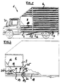
- the garbage collection vehicle 1 shown in FIG. 1 consists of a conventional light van with a vehicle frame 2 which carries a driver's cab 3 at its front end.
- a pivotable frame 7 which is pivotable about an axis 4 at the rear end region of the vehicle frame 2.
- a hydraulic cylinder 5 is provided, the piston rod of which is articulated on the swivel frame 7 and the cylinder of which is articulated on the vehicle frame 2.
- a container 6 is fastened by releasable locking devices, which is provided in a known and not shown manner with a closable, rear discharge opening. The container 6 can thus be emptied by pivoting the swivel frame 7 and opening the pouring opening.
- the dumping unit 8 is arranged between the driver's cab 3 and the container 6. This can be part of the container 6. she can also be separated from the container 6, so that the container 6 can be detached from the refuse collection vehicle while leaving the dumping unit 8. This is useful if the filled containers are to be driven separately and replaced with empty ones.
- the dumping unit 8 consists of a receiving space 9 which is delimited on both sides of the refuse collection vehicle 1 by walls 10, the upper loading edges 11 of which are arranged so low that refuse workers can conveniently throw filled bags over them into the receiving space 9.
- the upper edge 11 of the side walls of the receiving space is expediently located approximately in the region or just below the lower frame profile of the window of the driver's cab 3.
- the receiving space 9 is provided above its base 13 with a grate 14 forming an intermediate base.
- the grate 14 consists of rods or tubes running parallel in the longitudinal direction of the vehicle.
- the grate has a horizontal section 15 on the container side and a sloping section 16 on the cab side.
- a shaft 19 is pivotally mounted in the carriage 17, on which tines 20 are fastened, which form a rake-like slide and penetrate the bars of the grate 14.
- the opening 25 is closed by a pivotable sheet or a rubber mat construction, through which the waste can be inserted into the container 6, but which prevent falling back into the receiving space.
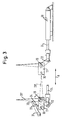
- Fig. 3 the slide arrangement is shown in an enlarged view, with the modification compared to the illustration in Fig. 2, that the carriage 17 is locked in its advanced position in the area of the rear wall of the cab until the row of tines its approximately horizontal position 20, '' has erected into its approximately vertical extension position 20 '.
- the slide 17 in its lateral guides (not shown) is moved back and forth in the direction of the double bearing A.
- the carriage 17 is laterally provided with at least one protruding pin 30, which comes into coupling engagement with the pawl 31 when the carriage 17 is displaced in the direction of the driver's cab.
- the pawl 31 is mounted in the region of the rear wall of the driver's cab to be pivotable about a transverse axis.
- the pawl 31 has a hook 33, which has a ramp-shaped on its front Bevel 34 is provided.
- the pawl 31 has a nose 32 which extends the pawl lever towards the front.
- the slide 17 can be seen shortly before the end of its insertion movement, in which the row of tines 20 is perpendicular to the slide guide.
- the row of tines 20 is held in that it is supported against a stop of the carriage 17, while the carriage is pulled by the pressure-medium piston-cylinder unit 18 via the crank-like lever 22 in the insertion direction of the waste.
- the piston-cylinder unit 18 is switched over to the extension direction of the piston rod 24.
- the row of tines 20 folds into position 20, ′′ under the grate 15.
- the pin 30 runs down the ramp 34 of the hook of the pawl 31 until the hook 33 engages in a locking manner behind the pin 30. If the piston-cylinder unit 18 is now switched back to the insert, the pawl 31 holds the slide 17 firmly over the pin 30 until the row of tines 20 'has raised up so far that at least one tine runs up against the nose 32 of the pawl lever 31 and pulls it out their locking position. During the subsequent insertion movement of the carriage 17, the row of tines 20 'is thus vertical so that it takes the waste to be inserted into the container.
- crank-like pivot lever 22 is fastened to the shaft 19 mounted on the carriage 17, which carries the row of tines 20.
Landscapes
- Engineering & Computer Science (AREA)
- Mechanical Engineering (AREA)
- Refuse-Collection Vehicles (AREA)
- Refuse Collection And Transfer (AREA)
Claims (13)
- Véhicule de ramassage d'ordures (1) entraîné par moteur pour recevoir des sacs de déchets et/ou des déchets vidés des récipients d'ordures, de préférence de déchets réutilisables, avec un conteneur (6) et une unité de versement (8) disposée entre le conteneur (6) et la cabine de conduite (3), qui est contituée d'une enceinte de réception (9) qui présente au moins une ouverture de versement latérale qui est délimitée vers le bas par une paroi latérale (10) dont l'arête supérieure (11) se situe à peu près dans la zone médiane de la porte de la cabine de conduite (3) et de laquelle un poussoir (20) déplaçable suivant un mouvement alternatif dans la direction longitudinale du véhicule transporte les déchets à travers une ouverture (25) pouvant être fermée dans le conteneur,
caractérisé en ce que,
un plancher intermédiaire de l'enceinte de réception (9) est constitué d'une grille (14) en tiges ou tubes parallèles les uns aux autres s'étendant dans la direction longitudinale du véhicule, à travers laquelle passent les dents (20) du poussoir configuré en rateau. - Véhicule de ramassage d'ordures selon la revendication 1, caractérisé en ce que la grille (14) remonte vers la cabine de conduite en biais ou en forme de courbe.
- Véhicule de ramassage d'ordures selon la revendication 1 ou 2, caractérisé en ce que le tronçon (15) essentiellement horizontal de la grille (14) présente sur son côté opposé à la cabine de conduite un tronçon avec une courbure en forme d'arc orientée vers le haut.
- Véhicule de ramassage d'ordures selon l'une des revendications 1 à 3, caractérisé en ce que les dents (20) du poussoir, dans la position sortie se situent au voisinage de la paroi terminale à la cabine de conduite (3) en dessous du tronçon montant (16) de la grille (14).
- Véhicule de ramassage d'ordures selon l'une des revendications 1 à 4, caractérisé en ce que le poussoir, lors de son déplacement en direction de la cabine de conduite (3), est rabattu dans un plan essentiellement horizontal où il se situe également au voisinage du tronçon horizontal (15) de la grille (14) sous les tiges de celle-ci.
- Véhicule de ramassage d'ordures selon l'une des revendications 1 à 5, caractérisé en ce que les dents du poussoir sont pivotées au voisinage de leur point de retour côté cabine de conduite de leur position (20'') à peu près horizontale en une position verticale (20').
- Véhicule de ramassage d'ordures selon l'une des revendications 1 à 6, caractérisé en ce que le point de retour côté cabine de conduite du poussoir en forme de rateau (20) se situe en dessous du tronçon montant (16) de la grille (14).
- Véhicule de ramassage d'ordures selon l'une des revendications 1 à 7, caractérisé en ce que le poussoir (20) est logé à un chariot (17) déplaçable dans des guidages.
- Véhicule de ramassage d'ordures selon l'une des revendications 1 à 9, caractérisé en ce que les dents (20) du poussoir sont fixées à un arbre (19) logé au chariot qui porte à la manière d'une manivelle un levier (22) auquel est articulée la tige de piston d'une unité à piston et à cylindre à fluide sous pression déplaçant le chariot (17) suivant un mouvement alternatif de façon que celle-ci fasse pivoter le poussoir, lors du mouvement de retour en direction de la cabine de conduite (3), en une position à peu près horizontale, et lors du mouvement de rentrage dans une position à peu près verticale.
- Véhicule de ramassage d'ordures selon la revendication 9, caractérisé en ce que le chariot (17) est pourvu d'une pièce d'accouplement (30) qui vient en prise d'accouplement dans la zone terminale du mouvement de retour avec une contre-pièce d'accouplement (31) au voisinage de la paroi arrière de la cabine de conduite, et en ce que l'accouplement des deux pièces d'accouplement est relâché par le mouvement de pivotement d'au moins une dent (20) de la rangée de dents en une position à peu près à angle droit relativement au guidage de chariot.
- Véhicule de ramassage d'ordures selon la revendiction 10, caractérisé en ce que l'accouplement est constitué d'un tenon (30) disposé au chariot (17) et d'un cliquet (31) solidaire du bâti qui est pourvu d'un ergot (32) ou analogue allongé, qui est disposé de telle sorte qu'une dent (20) dans la zone finale de son mouvement de redressement sorte celui-ci de sa prise de verrouillage avec le tenon (30).
- Véhicule de ramassage d'ordures selon l'une des revendications 8 à 11, caractérisé en ce que le chariot (17) porte à son côté inférieur des brosses passant sur le plancher (13) de l'enceinte de réception (9).
- Véhicule de ramassage d'ordures selon l'une des revendications 1 à 12, caractérisé en ce que le conteneur est pourvu d'un plancher remontant vers l'arrière.
Applications Claiming Priority (2)
| Application Number | Priority Date | Filing Date | Title |
|---|---|---|---|
| DE4314712A DE4314712A1 (de) | 1993-05-04 | 1993-05-04 | Motorgetriebenes Müllsammelfahrzeug |
| DE4314712 | 1993-05-04 |
Publications (3)
| Publication Number | Publication Date |
|---|---|
| EP0626323A2 EP0626323A2 (fr) | 1994-11-30 |
| EP0626323A3 EP0626323A3 (fr) | 1995-01-11 |
| EP0626323B1 true EP0626323B1 (fr) | 1997-06-11 |
Family
ID=6487140
Family Applications (1)
| Application Number | Title | Priority Date | Filing Date |
|---|---|---|---|
| EP94105093A Expired - Lifetime EP0626323B1 (fr) | 1993-05-04 | 1994-03-30 | Véhicule de ramassage d'ordures |
Country Status (3)
| Country | Link |
|---|---|
| EP (1) | EP0626323B1 (fr) |
| DE (2) | DE4314712A1 (fr) |
| ES (1) | ES2102717T3 (fr) |
Family Cites Families (3)
| Publication number | Priority date | Publication date | Assignee | Title |
|---|---|---|---|---|
| US3170578A (en) * | 1959-11-18 | 1965-02-23 | Stephen I Moreland | Garbage truck packing blade actuation |
| AU430550B2 (en) * | 1967-12-08 | 1972-11-30 | THOMAS BARRY RICHARDS and JUWAN CHARLES RICHARDS | Refuse vehicle |
| DE1757782A1 (de) * | 1968-06-12 | 1971-04-08 | Beck Stahlbau Fertigbau H | Kratzboden fuer landwirtschaftliche Geraete |
-
1993
- 1993-05-04 DE DE4314712A patent/DE4314712A1/de not_active Withdrawn
-
1994
- 1994-03-30 EP EP94105093A patent/EP0626323B1/fr not_active Expired - Lifetime
- 1994-03-30 DE DE59403078T patent/DE59403078D1/de not_active Expired - Fee Related
- 1994-03-30 ES ES94105093T patent/ES2102717T3/es not_active Expired - Lifetime
Also Published As
| Publication number | Publication date |
|---|---|
| DE59403078D1 (de) | 1997-07-17 |
| EP0626323A3 (fr) | 1995-01-11 |
| EP0626323A2 (fr) | 1994-11-30 |
| ES2102717T3 (es) | 1997-08-01 |
| DE4314712A1 (de) | 1994-11-10 |
Similar Documents
| Publication | Publication Date | Title |
|---|---|---|
| DE2558433C3 (de) | Müllsammei- und Transportsystem | |
| EP0235784B1 (fr) | Dispositif de culbutage pour un véhicule à ordures | |
| DE1556516C3 (de) | Vorrichtung zum kontinuierlichen oder diskontinuierlichen Beladen des Ladebehälters eines Müllfahrzeuges | |
| DE3537546A1 (de) | Mehrkammer-abfallsammelfahrzeug | |
| DE2327889B2 (de) | Müllfahrzeug | |
| DE2126780A1 (de) | Mullabfuhrwagen | |
| DE3543102C2 (fr) | ||
| DE69400850T2 (de) | Müllsammelfahrzeug mit einem festen hinteren Einschüttgehäuse und einer Vorrichtung zum Heben und Entleeren von Müllbehältern | |
| DE3121323A1 (de) | "lade- und verdichtungseinrichtung fuer einen fahrbaren oder stillstehenden muellbehaelter" | |
| DE3425083A1 (de) | Fahrzeug zum transport von muell o.dgl. | |
| EP2085330A1 (fr) | Véhicule pour déchets avec au moins un récipient collecteur et un dispositif de chargement | |
| DE3720442C2 (fr) | ||
| EP0626323B1 (fr) | Véhicule de ramassage d'ordures | |
| DE69400482T2 (de) | Vorrichtung und Verfahren zum getrennten Sammeln und Verdichten von Müll in einem Müllsammelfahrzeug | |
| DE1274963B (de) | Muellfahrzeug | |
| DE4417119C2 (de) | Motorgetriebenes Müllsammelfahrzeug | |
| EP0795494B1 (fr) | Véhicule pour la collecte des ordures | |
| DE4237407C1 (de) | Müllsammelfahrzeug | |
| AT202070B (de) | An einem Kehrichtwagen angebrachte Stopfvorrichtung | |
| DE20217320U1 (de) | Fahrzeug zur Entsorgung von Abfällen mit Preßeinrichtung | |
| AT208300B (de) | Einschüttvorrichtung an Müll-Abfuhrfahrzeugen mit Einschüttasche und hin- und herbewegter Transportplatte | |
| DE3402965A1 (de) | Transportabler sammelbehaelter fuer muell | |
| DE4243112A1 (de) | Müllsammelfahrzeug | |
| DE102010037655A1 (de) | Abfallsammelfahrzeug | |
| DE1459648C (fr) |
Legal Events
| Date | Code | Title | Description |
|---|---|---|---|
| PUAI | Public reference made under article 153(3) epc to a published international application that has entered the european phase |
Free format text: ORIGINAL CODE: 0009012 |
|
| PUAL | Search report despatched |
Free format text: ORIGINAL CODE: 0009013 |
|
| AK | Designated contracting states |
Kind code of ref document: A2 Designated state(s): BE DE ES FR GB IT NL |
|
| AK | Designated contracting states |
Kind code of ref document: A3 Designated state(s): BE DE ES FR GB IT NL |
|
| 17P | Request for examination filed |
Effective date: 19941207 |
|
| 17Q | First examination report despatched |
Effective date: 19960531 |
|
| GRAG | Despatch of communication of intention to grant |
Free format text: ORIGINAL CODE: EPIDOS AGRA |
|
| GRAH | Despatch of communication of intention to grant a patent |
Free format text: ORIGINAL CODE: EPIDOS IGRA |
|
| GRAH | Despatch of communication of intention to grant a patent |
Free format text: ORIGINAL CODE: EPIDOS IGRA |
|
| GRAA | (expected) grant |
Free format text: ORIGINAL CODE: 0009210 |
|
| AK | Designated contracting states |
Kind code of ref document: B1 Designated state(s): BE DE ES FR GB IT NL |
|
| REF | Corresponds to: |
Ref document number: 59403078 Country of ref document: DE Date of ref document: 19970717 |
|
| GBT | Gb: translation of ep patent filed (gb section 77(6)(a)/1977) |
Effective date: 19970701 |
|
| REG | Reference to a national code |
Ref country code: ES Ref legal event code: FG2A Ref document number: 2102717 Country of ref document: ES Kind code of ref document: T3 |
|
| ET | Fr: translation filed | ||
| PLBE | No opposition filed within time limit |
Free format text: ORIGINAL CODE: 0009261 |
|
| STAA | Information on the status of an ep patent application or granted ep patent |
Free format text: STATUS: NO OPPOSITION FILED WITHIN TIME LIMIT |
|
| 26N | No opposition filed | ||
| PGFP | Annual fee paid to national office [announced via postgrant information from national office to epo] |
Ref country code: DE Payment date: 19991216 Year of fee payment: 7 |
|
| PGFP | Annual fee paid to national office [announced via postgrant information from national office to epo] |
Ref country code: BE Payment date: 19991222 Year of fee payment: 7 |
|
| PGFP | Annual fee paid to national office [announced via postgrant information from national office to epo] |
Ref country code: FR Payment date: 19991231 Year of fee payment: 7 |
|
| PGFP | Annual fee paid to national office [announced via postgrant information from national office to epo] |
Ref country code: ES Payment date: 20000302 Year of fee payment: 7 |
|
| PGFP | Annual fee paid to national office [announced via postgrant information from national office to epo] |
Ref country code: GB Payment date: 20000329 Year of fee payment: 7 |
|
| PGFP | Annual fee paid to national office [announced via postgrant information from national office to epo] |
Ref country code: NL Payment date: 20000331 Year of fee payment: 7 |
|
| PG25 | Lapsed in a contracting state [announced via postgrant information from national office to epo] |
Ref country code: GB Free format text: LAPSE BECAUSE OF NON-PAYMENT OF DUE FEES Effective date: 20010330 |
|
| PG25 | Lapsed in a contracting state [announced via postgrant information from national office to epo] |
Ref country code: ES Free format text: LAPSE BECAUSE OF NON-PAYMENT OF DUE FEES Effective date: 20010331 Ref country code: BE Free format text: LAPSE BECAUSE OF NON-PAYMENT OF DUE FEES Effective date: 20010331 |
|
| BERE | Be: lapsed |
Owner name: EDELHOFF POLYTECHNIK G.M.B.H. & CO. Effective date: 20010331 |
|
| PG25 | Lapsed in a contracting state [announced via postgrant information from national office to epo] |
Ref country code: NL Free format text: LAPSE BECAUSE OF NON-PAYMENT OF DUE FEES Effective date: 20011001 |
|
| GBPC | Gb: european patent ceased through non-payment of renewal fee |
Effective date: 20010330 |
|
| PG25 | Lapsed in a contracting state [announced via postgrant information from national office to epo] |
Ref country code: FR Free format text: LAPSE BECAUSE OF NON-PAYMENT OF DUE FEES Effective date: 20011130 |
|
| NLV4 | Nl: lapsed or anulled due to non-payment of the annual fee |
Effective date: 20011001 |
|
| REG | Reference to a national code |
Ref country code: FR Ref legal event code: ST |
|
| PG25 | Lapsed in a contracting state [announced via postgrant information from national office to epo] |
Ref country code: DE Free format text: LAPSE BECAUSE OF NON-PAYMENT OF DUE FEES Effective date: 20020101 |
|
| REG | Reference to a national code |
Ref country code: ES Ref legal event code: FD2A Effective date: 20030303 |
|
| PG25 | Lapsed in a contracting state [announced via postgrant information from national office to epo] |
Ref country code: IT Free format text: LAPSE BECAUSE OF NON-PAYMENT OF DUE FEES;WARNING: LAPSES OF ITALIAN PATENTS WITH EFFECTIVE DATE BEFORE 2007 MAY HAVE OCCURRED AT ANY TIME BEFORE 2007. THE CORRECT EFFECTIVE DATE MAY BE DIFFERENT FROM THE ONE RECORDED. Effective date: 20050330 |