EP0626563A1 - Dispositif de mesure de positions - Google Patents
Dispositif de mesure de positions Download PDFInfo
- Publication number
- EP0626563A1 EP0626563A1 EP94106452A EP94106452A EP0626563A1 EP 0626563 A1 EP0626563 A1 EP 0626563A1 EP 94106452 A EP94106452 A EP 94106452A EP 94106452 A EP94106452 A EP 94106452A EP 0626563 A1 EP0626563 A1 EP 0626563A1
- Authority
- EP
- European Patent Office
- Prior art keywords
- phase
- track
- optical
- hologram scale
- tracks
- Prior art date
- Legal status (The legal status is an assumption and is not a legal conclusion. Google has not performed a legal analysis and makes no representation as to the accuracy of the status listed.)
- Granted
Links
- 230000003287 optical effect Effects 0.000 claims abstract description 36
- 230000005855 radiation Effects 0.000 claims description 25
- 238000005259 measurement Methods 0.000 claims description 21
- 239000013307 optical fiber Substances 0.000 claims description 2
- 239000004065 semiconductor Substances 0.000 claims description 2
- 230000007704 transition Effects 0.000 abstract description 5
- 238000012545 processing Methods 0.000 description 9
- 230000008901 benefit Effects 0.000 description 7
- 238000000034 method Methods 0.000 description 6
- 238000011156 evaluation Methods 0.000 description 5
- 230000008859 change Effects 0.000 description 4
- 238000011161 development Methods 0.000 description 4
- 230000018109 developmental process Effects 0.000 description 4
- 230000010363 phase shift Effects 0.000 description 3
- 238000006073 displacement reaction Methods 0.000 description 2
- 238000011426 transformation method Methods 0.000 description 2
- 238000012935 Averaging Methods 0.000 description 1
- 238000010276 construction Methods 0.000 description 1
- 238000013461 design Methods 0.000 description 1
- 238000009826 distribution Methods 0.000 description 1
- 238000005516 engineering process Methods 0.000 description 1
- 230000006870 function Effects 0.000 description 1
- 230000000717 retained effect Effects 0.000 description 1
- 230000009466 transformation Effects 0.000 description 1
Images

Classifications
-
- G—PHYSICS
- G01—MEASURING; TESTING
- G01D—MEASURING NOT SPECIALLY ADAPTED FOR A SPECIFIC VARIABLE; ARRANGEMENTS FOR MEASURING TWO OR MORE VARIABLES NOT COVERED IN A SINGLE OTHER SUBCLASS; TARIFF METERING APPARATUS; MEASURING OR TESTING NOT OTHERWISE PROVIDED FOR
- G01D5/00—Mechanical means for transferring the output of a sensing member; Means for converting the output of a sensing member to another variable where the form or nature of the sensing member does not constrain the means for converting; Transducers not specially adapted for a specific variable
- G01D5/26—Mechanical means for transferring the output of a sensing member; Means for converting the output of a sensing member to another variable where the form or nature of the sensing member does not constrain the means for converting; Transducers not specially adapted for a specific variable characterised by optical transfer means, i.e. using infrared, visible, or ultraviolet light
- G01D5/32—Mechanical means for transferring the output of a sensing member; Means for converting the output of a sensing member to another variable where the form or nature of the sensing member does not constrain the means for converting; Transducers not specially adapted for a specific variable characterised by optical transfer means, i.e. using infrared, visible, or ultraviolet light with attenuation or whole or partial obturation of beams of light
- G01D5/34—Mechanical means for transferring the output of a sensing member; Means for converting the output of a sensing member to another variable where the form or nature of the sensing member does not constrain the means for converting; Transducers not specially adapted for a specific variable characterised by optical transfer means, i.e. using infrared, visible, or ultraviolet light with attenuation or whole or partial obturation of beams of light the beams of light being detected by photocells
- G01D5/36—Forming the light into pulses
- G01D5/38—Forming the light into pulses by diffraction gratings
-
- G—PHYSICS
- G01—MEASURING; TESTING
- G01D—MEASURING NOT SPECIALLY ADAPTED FOR A SPECIFIC VARIABLE; ARRANGEMENTS FOR MEASURING TWO OR MORE VARIABLES NOT COVERED IN A SINGLE OTHER SUBCLASS; TARIFF METERING APPARATUS; MEASURING OR TESTING NOT OTHERWISE PROVIDED FOR
- G01D5/00—Mechanical means for transferring the output of a sensing member; Means for converting the output of a sensing member to another variable where the form or nature of the sensing member does not constrain the means for converting; Transducers not specially adapted for a specific variable
- G01D5/26—Mechanical means for transferring the output of a sensing member; Means for converting the output of a sensing member to another variable where the form or nature of the sensing member does not constrain the means for converting; Transducers not specially adapted for a specific variable characterised by optical transfer means, i.e. using infrared, visible, or ultraviolet light
- G01D5/32—Mechanical means for transferring the output of a sensing member; Means for converting the output of a sensing member to another variable where the form or nature of the sensing member does not constrain the means for converting; Transducers not specially adapted for a specific variable characterised by optical transfer means, i.e. using infrared, visible, or ultraviolet light with attenuation or whole or partial obturation of beams of light
- G01D5/34—Mechanical means for transferring the output of a sensing member; Means for converting the output of a sensing member to another variable where the form or nature of the sensing member does not constrain the means for converting; Transducers not specially adapted for a specific variable characterised by optical transfer means, i.e. using infrared, visible, or ultraviolet light with attenuation or whole or partial obturation of beams of light the beams of light being detected by photocells
- G01D5/347—Mechanical means for transferring the output of a sensing member; Means for converting the output of a sensing member to another variable where the form or nature of the sensing member does not constrain the means for converting; Transducers not specially adapted for a specific variable characterised by optical transfer means, i.e. using infrared, visible, or ultraviolet light with attenuation or whole or partial obturation of beams of light the beams of light being detected by photocells using displacement encoding scales
- G01D5/34776—Absolute encoders with analogue or digital scales
- G01D5/34792—Absolute encoders with analogue or digital scales with only digital scales or both digital and incremental scales
Definitions
- the invention is based on a position measuring device according to the preamble of the main claim.
- a device for absolute two-dimensional position measurement of a part in relation to an optical measuring arrangement is known, in which the surface of the part is designed as a hologram scale.
- the information contained on the hologram scale is read out by interference with a reference wave using an optical measuring wave which is directed onto the hologram scale and diffracted there.
- the interfered waves are recorded by an optical measuring arrangement which contains at least two sensors.
- the absolute position is determined from the phase relationships between the signals output by the sensors. Details of the design of the hologram scale are not contained in DE-OS 39 30 554.
- the invention has for its object to provide a position measuring device with a hologram scale, which enables a large absolute measuring range and a high position resolution.
- a first embodiment of the position measuring device provides that the hologram scale has a first and at least a second track, the tracks each being designed as an optical grating.
- the grids each have a regular structure, which is characterized by the grating constant.
- the lattice constants of the individual lattices each differ by a predetermined amount.
- the information about the position of the part in relation to the optical measuring arrangement is contained in the wavefront diffracted on the hologram scale, which reaches the optical measuring arrangement.
- Different phase positions occur simultaneously at different locations in the wavefront. Wavefronts diffracted at different positions on the hologram scale clearly differ from one another, so that an absolute position assignment is possible.
- the optical measuring arrangement contains sensors which are assigned to the different locations of the wave front.
- the electrical signals emitted by the individual sensors either have different phase positions or in each case emit signal levels that can be calculated back to phase positions, for example, as part of a phase shifting method.
- a position can be determined from the individual phase positions of the signals emitted by the sensors of the optical measuring arrangement and, if appropriate, from phase difference measurements.
- the measurement error of the position measuring device is essentially determined by the accuracy of the phase measurements in relation to the track with the smallest lattice constant and, if appropriate through the accuracy in determining the phase differences.
- An increase in the number of tracks beyond two tracks enables the absolute measuring range to be easily expanded without the accuracy of the phase measurements or, if appropriate, that of the phase difference measurements having to be increased.
- the advantage of the first embodiment of the position measuring device according to the invention is that a simple grating structure can be used, which is characterized by the grating constant.
- a second embodiment of the position measuring device provides that the hologram scale again has a first and at least one second track and that the tracks are again designed as optical gratings.
- the difference from the first version is that the lattice constants of the individual lattices are identical and that the lattice in the second track and the other tracks, if any, have fields in which the initial phase is fixed to a predetermined value achieved by shifting the grid in the relevant field by a fraction of a grid constant.
- the grid of the first track is provided as a reference grid.
- a change in position by a lattice constant changes the phase of the output signal of the at least one sensor provided for this track in the optical measuring arrangement by 360 °.
- the grids of the second and possibly further tracks with the fields enable simple digital coding to be set up.
- the hologram scale is shifted, in addition to the phase curve already described for the first track, there are jump points in the wavefront at the transition points between the individual fields with a changed initial phase.
- the radiation diffracted at the grids with the fields thus has a phase shift with respect to the radiation diffracted at the first grating, which corresponds to the initial phase of the grating of the field in question.
- the position resolution of the second embodiment of the position measuring device according to the invention is limited by the length of the individual fields.
- the main advantage is that there are no high demands on the accuracy of the phase measurement. If, for example, the values 0 ° and, for example, 180 ° are selected for the initial phase of the individual fields (shifting the grid in the field by half a grid period), the phase must only be determinable to +/- 90 °.
- the main advantage of this embodiment is that the absolute measuring range can be expanded considerably and at the same time the position resolution is retained. A position measurement in the meter range can be carried out with an accuracy of a few nanometers.
- the optical measuring arrangement is advantageously designed as a photodiode array or preferably as a photodiode array. With this measure, an inexpensive implementation of the optical measuring arrangement can be implemented with the least wiring effort.
- the position measuring device is equally suitable for measuring a linear, possibly two-dimensional displacement or a rotation of one part in each case with respect to another part, the absolute position always being able to be specified without further measurements.
- FIG. 1 shows an embodiment of an apparatus for absolute position measurement according to the invention
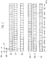
- FIG. 2 shows an embodiment of a hologram scale
- FIG. 3 shows phase profiles as a function of a position.
- FIG. 1 shows a part 10, the absolute position of which is to be determined in relation to an optical measuring arrangement 11.
- the position measuring device contains a radiation source 12, from the radiation of which a measuring wave 13 and a reference wave 14 are derived. Both the measuring and the reference waves 13, 14 are at least partially guided in a radiation waveguide 15.
- a modulator 16 (phase or frequency modulator) is arranged in the beam path of the reference wave 14.
- the measuring shaft 13 is on one Impact point 17 directed on the surface 19 of the part 10 provided with a hologram scale 18.
- the measuring shaft 13 diffracted at the point of impact is brought into interference with the reference shaft 14 on a beam splitter 20.
- a reception wave 21 extends from the beam splitter 20 and receives the optical measuring arrangement 11.
- the optical measuring arrangement 11 contains at least two sensors 22, 23, the output signals of which are fed to a signal processing arrangement 24.
- the position device according to the invention according to FIG. 1 works as follows:
- the information about the absolute position of the part 10 in relation to the optical measuring arrangement 11 is contained on the surface 19 of the part 10, which is designed as a hologram scale 18.
- the hologram scale 18 can also be produced separately and then connected to the surface 19 of the part 10.
- the structure of the hologram scale 18 can be calculated theoretically. A particularly advantageous structure is described in more detail below with reference to FIG. 2.
- the information contained in the hologram scale 18 is read out optically.
- the information is contained in the wavefront of the radiation diffracted on the surface 19. A different phase position occurs at different locations on the wavefront of the diffracted radiation.
- the wavefronts diffracted at different positions of the hologram scale 18 clearly differ from one another, so that an absolute position assignment is possible.
- the phase positions in the wavefront of the diffracted radiation can be technically evaluated by interference with the reference wave 14.
- the waves 13, 14, which are brought into interference, for example on a beam splitter 20, reach the optical measuring arrangement 11 as receiving wave 21.
- the optical measuring arrangement 11 contains at least the two sensors 22, 23, which are exposed to the wave front of the reception wave 21. Since different phases are present at different locations on the wave front of the reception wave 21, the sensors 22, 23 receive signals with correspondingly different phase positions.
- phase shift method can be used, in which the phase of the radiation is changed over time.
- the modulator 16 is designed, for example, as a piezoelectric component that enables the optical path length to be changed easily by distances that lie in the wavelength range of the radiation used.
- a first possibility in heterodyne technology provides that the modulator is designed as a frequency modulator that changes the frequency of the reference radiation 14.
- the sensors 22, 23 emit a signal which has a frequency which has the difference frequency between the reference radiation 14 and the measurement radiation 13, the information also being contained in the phase position.
- the modulator 16 is, for example, an acousto-optical modulator.
- a differential frequency provides for the use of a radiation source 12 which can be modulated in frequency, for example a semiconductor laser, the modulator 16 causing a transit time difference between the two radiations 13, 14, which leads to a difference frequency which is always present.
- the modulation frequency can be set to a value that is easy to handle in the signal processing arrangement 24. Current values are in the range from 1 MHz to 100 MHz.
- the position measuring device according to the invention then works as a heterodyne interferometer. With such a heterodyne interferometer, the signal processing arrangement 24 can use either the signal emitted by a sensor 22, 23 or the modulation signal provided by a modulation frequency generator as the reference phase.
- the evaluation of phase relationships carried out in the signal processing arrangement 24 makes it possible to specify an absolute position of the part 10 with respect to the optical measuring arrangement 11.
- the signal processing arrangement 24 can both the absolute phase position of the individual signals and the phase difference between those of the two sensors 22 , 23 determine the signals emitted immediately.
- the result of the position measurement is available.
- the position can be determined two-dimensionally, a one-dimensional position measurement being included as a trivial case in the two-dimensional measurement.
- FIG. 2 shows an advantageous embodiment of the hologram scale 18.
- the hologram scale 18 contains a first group of tracks S0-S m and a second group of tracks S m + 1 -S m . Each of these tracks S0-S m , S m + 1 -S n is designed as an optical grating.
- the lattices of the traces S0-S m are each fully characterized by the lattice constants d0-d m . It is essential that the lattice constants d0-d m each differ by a predetermined amount.
- the definition can be made, for example, as follows:
- the tracks S0-S m can be described as analog tracks because the phase of the radiation diffracted by a single track S o - S m and the position x have a linear, analog connection (modulo 360 °).
- a high position resolution is thus possible, which is determined by the phase of the radiation diffracted by the track S0 with the smallest grating constant d0.
- the position measuring device according to the invention enables a large absolute measuring range, which can be determined by the phase difference of the radiation diffracted by the individual tracks S0-S m .
- the tracks S m + 1 -S n can be described as digital tracks.
- At least one digital track S m + 1 -S n is to be provided in connection with an analog track S0.
- the grid of the analog track S0 has the same grid constant d0 as the grid of the at least one digital track S m + 1 -S n .
- the analog track S0 serves as a reference.
- the digital tracks S m + 1 -S n are grids with identical grating constants, for example d0, but which differ in the initial phase within individual fields 30-34. If only one digital track S m + 1 - S n is present, the phase position changes for successive fields 30, 31; 31, 32; 32, 33; 33, 34. If more than one track S m + 1 -S n is provided, the transition from one field to the other changes at least one track S m + 1 - S n to the initial phase. There is no change in the lattice structure within the fields 30-34. In the exemplary embodiment shown in FIG. 2, the track S m + 1 has the initial phase 0 ° in the fields 30, 33, 34 and the initial phase 180 ° in the fields 31, 32.
- the phase of the radiation diffracted on the gratings of the tracks S m + 1 to S n is thus identical in the exemplary embodiment except for the initial phase of the individual fields 30-34 with the phase of the radiation diffracted on the analog track S.
- the hologram scale 18 is shifted, there are jump points in the phase positions at the transition points between the individual fields 30-34.
- the radiation diffracted on the digital tracks S m + 1 -S n thus has a phase shift with respect to the radiation diffracted on the analog track S0, which corresponds to the initial phase of the grating of the relevant field 30-34.
- the values of the initial phase of the individual fields 30 - 34 can be digitally encoded, for example by using 0 ° and 180 ° (1 bit / track) or 0 °, 90 °, 180 ° and 270 ° (2 bit / track) as the initial phase be used.
- the achievable position resolution is given by the length of the individual fields 30-34. Assuming that the lattice constant of an analog track S0 and the at least one digital track S m + 1 -S n is a micrometer, the position resolution is several micrometers, corresponding to the number of grid lines within a field 30-34.
- the main advantage is that there are no high demands on the accuracy of the phase measurement. For example, if the values 0 ° and 180 ° are used for the initial phase of the individual fields 30 - 34, the phase position only has to be determinable to +/- 90 °.
- a particularly advantageous development provides for the combination of more than one analog track S0-S m with at least one digital track S m + 1 -S n .
- the absolute measuring range achieved with the analog tracks S0-S m can be expanded.
- the maximum length of the fields 30-34 of the digital tracks S m + 1 -S n must not exceed the uniqueness range achieved with the analog tracks S0-S m . Exceeding this is possible at any time without the absolute position measurement.
- the measured value becomes ambiguous, corresponding to at least one phase measurement or phase change of more than 360 °.
- the number of sensors 22, 23 in the optical measuring arrangement 11 is at least equal to the number of tracks S0-S m , S m + 1 -S n .
- the use of a photodiode array has proven itself in practical use, preferably the output signals of a plurality of individual ones Sensors are considered together, so that considerably more sensors than tracks are provided.
- the evaluation of signals from several sensors, which are assigned to a track S0-S m , S m + 1 -S n enables averaging, which reduces the influence of the noise signal.
- a further increase in the information during the evaluation is possible with a photodiode array, which enables a two-dimensional evaluation with the signals emitted by the optical measuring arrangement 11.
- the use of the photodiode array is particularly useful when the phase position is to be determined from an inverse Fourier transformation using the Fourier transformation method.
- phase profiles P0; P1; P0-P1; P diff shown depending on the location x.
- P0 is the output signal of a sensor 22, 23 which receives, for example, the part of the wavefront that is diffracted by the track S0 with the grating constant d o .
- P1 represents the phase profile of the signal which is emitted by the sensor 22, 23 which receives the part of the wave front which is diffracted by the track S 1.
- the hologram scale 18 is shifted by the amount of the lattice constant d0, the phase of the signal P0 changes from 0 ° to 360 °. With a further shift, the values are repeated periodically.
- phase curve P1 results in a corresponding manner, with a grid being used which has a grid constant d 1 deviating from d0 (in the example d 1> d o ).
- a phase change from the value 0 ° to 360 ° therefore results with a larger displacement of the hologram scale 18 in comparison to the phase curve P0.
- the phase curve P0-P1 shown in the third partial image is formed by forming the difference between the phase curves P0 and P1. It can be provided in the signal processing arrangement 24 that in the event of a negative result when forming the difference, the amount 360 ° must always be added to the result. The result is shown in the fourth field with the phase curve P diff .
- the position which has a certain measurement uncertainty can first be determined from the phase curve P diff . After the at least rough position has been determined, the signal-processing arrangement 24 can use either the phase profile P0 or the phase profile P1 for further highly accurate position determination. In another embodiment, position determination is also possible without using the phase profile P diff by comparing the individual phase profiles P0 and P1 with comparison values stored in a memory.
- phase profiles P0 and P1 shown in FIG. 3 are obtained from analog tracks S0-S m .
- the phase profiles which are obtained with the digital tracks S m + 1 -S n correspond to the phase profiles P0 and P1 shown in FIG. 3, except for the initial values of the phases which occur during the transitions between the individual fields 30-34 in the manner described can be changed.
- the phase curve begins, for example, at 0 ° and ends with a shift by the lattice constant d0 at 360 °. If the initial phase of the subsequent field is set to, for example, 180 °, the phase does not jump back from 360 ° to 0 ° when transitioning to this field, but from 360 ° to only 180 °.
- the device according to the invention according to FIG. 1 can largely be manufactured in an integrated look.
- the radiation is guided in light guides.
- An advantage of using optical fibers is that the optical measuring arrangement 11 can be set apart from the other components. The measure reduces the thermal load on the sensors 22, 23.
Landscapes
- Physics & Mathematics (AREA)
- General Physics & Mathematics (AREA)
- Optical Transform (AREA)
Applications Claiming Priority (2)
| Application Number | Priority Date | Filing Date | Title |
|---|---|---|---|
| DE4317064 | 1993-05-21 | ||
| DE4317064A DE4317064A1 (de) | 1993-05-21 | 1993-05-21 | Positionsmeßvorrichtung |
Publications (2)
| Publication Number | Publication Date |
|---|---|
| EP0626563A1 true EP0626563A1 (fr) | 1994-11-30 |
| EP0626563B1 EP0626563B1 (fr) | 1998-07-08 |
Family
ID=6488669
Family Applications (1)
| Application Number | Title | Priority Date | Filing Date |
|---|---|---|---|
| EP94106452A Revoked EP0626563B1 (fr) | 1993-05-21 | 1994-04-26 | Dispositif de mesure de positions avec l'échelle hologramme |
Country Status (2)
| Country | Link |
|---|---|
| EP (1) | EP0626563B1 (fr) |
| DE (2) | DE4317064A1 (fr) |
Families Citing this family (13)
| Publication number | Priority date | Publication date | Assignee | Title |
|---|---|---|---|---|
| JPH08219812A (ja) * | 1995-02-15 | 1996-08-30 | Canon Inc | 変位情報検出装置、変位情報検出用スケール及びこれを用いたドライブ制御装置 |
| DE19527421A1 (de) * | 1995-07-27 | 1997-01-30 | Bosch Gmbh Robert | Vorrichtung zur absoluten Positionsmessung |
| DE19528326C1 (de) * | 1995-08-02 | 1997-01-09 | Bosch Gmbh Robert | Vorrichtung zur absoluten Positionsmessung |
| DE19536039A1 (de) * | 1995-09-28 | 1997-04-03 | Bosch Gmbh Robert | Vorrichtung zur mehrdimensionalen Messung von Positionen oder Positionsänderungen |
| DE19536066A1 (de) * | 1995-09-28 | 1997-04-03 | Bosch Gmbh Robert | Optische Vorrichtung zum Messen eines Wegs oder Drehwinkels |
| DE19636386A1 (de) | 1996-09-09 | 1998-03-12 | Bosch Gmbh Robert | Anordnung zur Prüfung von Oberflächen |
| US6100979A (en) * | 1996-09-09 | 2000-08-08 | Robert Bosch Gmbh | Arrangement for the testing of surfaces |
| DE19637625A1 (de) * | 1996-09-16 | 1998-03-26 | Bosch Gmbh Robert | Motor oder Generator mit zwei relativ zueinander beweglich gelagerten Teilen und einer Vorrichtung zum interferometrischen Messen eines Weges oder Drehwinkels |
| WO1999027324A2 (fr) * | 1997-11-25 | 1999-06-03 | Microe, Inc. | Codeur absolu multipistes |
| DE19816951C2 (de) * | 1998-04-17 | 2000-08-10 | Fh Harz Wernigerode | Anordnung zur optischen Positions-, Bewegungsrichtungs- und Geschwindigkeitsbestimmung |
| DE10332413B3 (de) * | 2003-07-16 | 2005-04-28 | Ic Haus Gmbh | Positionsmessvorrichtung zum Ermitteln von Winkel- oder Längenpositionen |
| WO2007048611A1 (fr) * | 2005-10-28 | 2007-05-03 | Hahn-Schickard-Gesellschaft für angewandte Forschung e.V. | Élément de codage pour transmetteur de position |
| EP2623939B1 (fr) | 2012-02-03 | 2016-06-29 | Siemens Aktiengesellschaft | Dispositif d'établissement de valeurs de mesure ainsi que système doté d'une unité d'entraînement et d'un dispositif d'établissement de valeurs de mesure |
Citations (3)
| Publication number | Priority date | Publication date | Assignee | Title |
|---|---|---|---|---|
| US4395124A (en) * | 1977-12-23 | 1983-07-26 | Randwal Instrument Co., Inc. | Apparatus for position encoding |
| GB2138588A (en) * | 1983-04-19 | 1984-10-24 | Barr & Stroud Ltd | Optical Grating for Displacement Sensor |
| FR2615280A1 (fr) * | 1987-05-11 | 1988-11-18 | Canon Kk | Dispositif de mesure de la distance en mouvement relatif de deux objets mobiles l'un par rapport a l'autre |
Family Cites Families (1)
| Publication number | Priority date | Publication date | Assignee | Title |
|---|---|---|---|---|
| DE4125865C2 (de) * | 1991-08-03 | 1994-01-20 | Heidenhain Gmbh Dr Johannes | Längen- oder Winkelmeßeinrichtung |
-
1993
- 1993-05-21 DE DE4317064A patent/DE4317064A1/de not_active Withdrawn
-
1994
- 1994-04-26 EP EP94106452A patent/EP0626563B1/fr not_active Revoked
- 1994-04-26 DE DE59406389T patent/DE59406389D1/de not_active Revoked
Patent Citations (3)
| Publication number | Priority date | Publication date | Assignee | Title |
|---|---|---|---|---|
| US4395124A (en) * | 1977-12-23 | 1983-07-26 | Randwal Instrument Co., Inc. | Apparatus for position encoding |
| GB2138588A (en) * | 1983-04-19 | 1984-10-24 | Barr & Stroud Ltd | Optical Grating for Displacement Sensor |
| FR2615280A1 (fr) * | 1987-05-11 | 1988-11-18 | Canon Kk | Dispositif de mesure de la distance en mouvement relatif de deux objets mobiles l'un par rapport a l'autre |
Also Published As
| Publication number | Publication date |
|---|---|
| DE4317064A1 (de) | 1994-11-24 |
| DE59406389D1 (de) | 1998-08-13 |
| EP0626563B1 (fr) | 1998-07-08 |
Similar Documents
| Publication | Publication Date | Title |
|---|---|---|
| DE69633213T2 (de) | Drehwinkelgeber | |
| EP0262349B1 (fr) | Dispositif photoélectrique pour la mesure d'angles | |
| DE3844704C2 (fr) | ||
| DE3306709C2 (fr) | ||
| EP0137099B1 (fr) | Appareil de mesure | |
| DE3816247C2 (de) | Vorrichtung zur Messung einer Relativbewegung von zwei zueinander relativ bewegbaren Objekten | |
| EP0561015A1 (fr) | Mesure de phase interferométrique | |
| EP0626563B1 (fr) | Dispositif de mesure de positions avec l'échelle hologramme | |
| DE3417176A1 (de) | Photoelektrische messeinrichtung | |
| EP0455218A1 (fr) | Procédé et dispositif pour le mesurage d'un signal modulé en phase | |
| EP0254823A2 (fr) | Dispositif de mesure de position photoélectrique | |
| EP0141123A2 (fr) | Dispositif de mesure incrémental photoélectrique | |
| EP0670467A1 (fr) | Interféromètre | |
| EP0491749B1 (fr) | Dispositif de mesure de position absolue sur deux dimensions | |
| EP0352602A2 (fr) | Dispositif de mesure de position | |
| DE3933983A1 (de) | Schaltungsanordnung zur signalinterpolation und versetzungsmesseinrichtung mit der schaltungsanordnung | |
| DE4212281C2 (fr) | ||
| EP0421024B1 (fr) | Dispositif photoélectrique de mesure de position | |
| EP0590163B1 (fr) | Dispositif de mesure de longueurs ou d'angles | |
| EP0547270B1 (fr) | Appareil photoélectrique pour générer des signaux périodiques exempte d'harmoniques | |
| DE4313497C2 (de) | Verfahren und Gerät zum Bestimmen von Richtung und Geschwindigkeit eines Objektes | |
| EP1064517B1 (fr) | Procede et dispositif de mesure de longueur interferometrique absolue | |
| EP0628790A2 (fr) | Dispositif pour mesurer le mouvement entre deux objets | |
| DE1915228C3 (de) | Anordnung zur Messung mechanischer Verschiebungen | |
| EP0756155A2 (fr) | Dispositif de mesure de positions absolues |
Legal Events
| Date | Code | Title | Description |
|---|---|---|---|
| PUAI | Public reference made under article 153(3) epc to a published international application that has entered the european phase |
Free format text: ORIGINAL CODE: 0009012 |
|
| AK | Designated contracting states |
Kind code of ref document: A1 Designated state(s): CH DE FR GB IT LI |
|
| 17P | Request for examination filed |
Effective date: 19950530 |
|
| 17Q | First examination report despatched |
Effective date: 19961025 |
|
| GRAG | Despatch of communication of intention to grant |
Free format text: ORIGINAL CODE: EPIDOS AGRA |
|
| GRAG | Despatch of communication of intention to grant |
Free format text: ORIGINAL CODE: EPIDOS AGRA |
|
| GRAH | Despatch of communication of intention to grant a patent |
Free format text: ORIGINAL CODE: EPIDOS IGRA |
|
| GRAH | Despatch of communication of intention to grant a patent |
Free format text: ORIGINAL CODE: EPIDOS IGRA |
|
| GRAA | (expected) grant |
Free format text: ORIGINAL CODE: 0009210 |
|
| AK | Designated contracting states |
Kind code of ref document: B1 Designated state(s): CH DE FR GB IT LI |
|
| REG | Reference to a national code |
Ref country code: CH Ref legal event code: EP |
|
| REF | Corresponds to: |
Ref document number: 59406389 Country of ref document: DE Date of ref document: 19980813 |
|
| REG | Reference to a national code |
Ref country code: CH Ref legal event code: NV Representative=s name: SCINTILLA AG, DIREKTION |
|
| ET | Fr: translation filed | ||
| GBT | Gb: translation of ep patent filed (gb section 77(6)(a)/1977) |
Effective date: 19980915 |
|
| PGFP | Annual fee paid to national office [announced via postgrant information from national office to epo] |
Ref country code: GB Payment date: 19990412 Year of fee payment: 6 |
|
| PLBI | Opposition filed |
Free format text: ORIGINAL CODE: 0009260 |
|
| PGFP | Annual fee paid to national office [announced via postgrant information from national office to epo] |
Ref country code: CH Payment date: 19990426 Year of fee payment: 6 |
|
| PGFP | Annual fee paid to national office [announced via postgrant information from national office to epo] |
Ref country code: FR Payment date: 19990427 Year of fee payment: 6 |
|
| PLBF | Reply of patent proprietor to notice(s) of opposition |
Free format text: ORIGINAL CODE: EPIDOS OBSO |
|
| 26 | Opposition filed |
Opponent name: DR. JOHANNES HEIDENHAIN GMBH Effective date: 19990407 |
|
| PGFP | Annual fee paid to national office [announced via postgrant information from national office to epo] |
Ref country code: DE Payment date: 19990712 Year of fee payment: 6 |
|
| RDAH | Patent revoked |
Free format text: ORIGINAL CODE: EPIDOS REVO |
|
| RDAG | Patent revoked |
Free format text: ORIGINAL CODE: 0009271 |
|
| STAA | Information on the status of an ep patent application or granted ep patent |
Free format text: STATUS: PATENT REVOKED |
|
| 27W | Patent revoked |
Effective date: 19991120 |
|
| GBPR | Gb: patent revoked under art. 102 of the ep convention designating the uk as contracting state |
Free format text: 991120 |
|
| REG | Reference to a national code |
Ref country code: CH Ref legal event code: PL |