EP0626698B1 - Appareillage ayant un niveau de sûureté et méthode de détection d'une barre chutée et d'un mauvais fonctionnement dans la réponse des thermocouples, dans un réacteur à eau pressurisée - Google Patents
Appareillage ayant un niveau de sûureté et méthode de détection d'une barre chutée et d'un mauvais fonctionnement dans la réponse des thermocouples, dans un réacteur à eau pressurisée Download PDFInfo
- Publication number
- EP0626698B1 EP0626698B1 EP94303746A EP94303746A EP0626698B1 EP 0626698 B1 EP0626698 B1 EP 0626698B1 EP 94303746 A EP94303746 A EP 94303746A EP 94303746 A EP94303746 A EP 94303746A EP 0626698 B1 EP0626698 B1 EP 0626698B1
- Authority
- EP
- European Patent Office
- Prior art keywords
- rod
- core
- reactor
- dropped
- control rod
- Prior art date
- Legal status (The legal status is an assumption and is not a legal conclusion. Google has not performed a legal analysis and makes no representation as to the accuracy of the status listed.)
- Expired - Lifetime
Links
Images


Classifications
-
- G—PHYSICS
- G21—NUCLEAR PHYSICS; NUCLEAR ENGINEERING
- G21C—NUCLEAR REACTORS
- G21C17/00—Monitoring; Testing ; Maintaining
- G21C17/10—Structural combination of fuel element, control rod, reactor core, or moderator structure with sensitive instruments, e.g. for measuring radioactivity, strain
-
- G—PHYSICS
- G21—NUCLEAR PHYSICS; NUCLEAR ENGINEERING
- G21C—NUCLEAR REACTORS
- G21C7/00—Control of nuclear reaction
- G21C7/06—Control of nuclear reaction by application of neutron-absorbing material, i.e. material with absorption cross-section very much in excess of reflection cross-section
- G21C7/08—Control of nuclear reaction by application of neutron-absorbing material, i.e. material with absorption cross-section very much in excess of reflection cross-section by displacement of solid control elements, e.g. control rods
- G21C7/12—Means for moving control elements to desired position
-
- Y—GENERAL TAGGING OF NEW TECHNOLOGICAL DEVELOPMENTS; GENERAL TAGGING OF CROSS-SECTIONAL TECHNOLOGIES SPANNING OVER SEVERAL SECTIONS OF THE IPC; TECHNICAL SUBJECTS COVERED BY FORMER USPC CROSS-REFERENCE ART COLLECTIONS [XRACs] AND DIGESTS
- Y02—TECHNOLOGIES OR APPLICATIONS FOR MITIGATION OR ADAPTATION AGAINST CLIMATE CHANGE
- Y02E—REDUCTION OF GREENHOUSE GAS [GHG] EMISSIONS, RELATED TO ENERGY GENERATION, TRANSMISSION OR DISTRIBUTION
- Y02E30/00—Energy generation of nuclear origin
- Y02E30/30—Nuclear fission reactors
Definitions
- This invention is directed to a pressurized water reactor having a safety system grade system for automatically blocking withdrawal of control rods in response to a dropped control rod.
- the reactivity of a pressurized water reactor is controlled by regulating the concentration of a neutron absorber, such as boron, in reactor coolant circulated through the reactor core, and by control rods which can be inserted into the reactor core. Changes in boron concentration have a core wide effect while the insertion of control rods is more localized. Typically, the control rods are stepped into and out of the core, but can be dropped into the core rapidly to shut down the core should the need arise. It is possible that during normal operation one or more individual control rod drives could malfunction and drop control rods into the core. This results in a reduction in the reactivity of the core with consequent lowering of the average temperature of coolant exiting the core.
- a neutron absorber such as boron
- the conventional control system responds to this reduction in temperature by withdrawing specified control rods in order to raise the core average temperature to a set point level. This can result in excessive heat rise in another part of the core as the control system attempts to compensate for the reduction in core reactivity.
- Assignee of the present invention has developed an advanced pressurized water reactor which is protected by passive safety systems. That is, no operator intervention is required to maintain safe operating conditions in the reactor despite various postulated malfunctions.
- the control strategy for this advanced pressurized water reactor calls for load following primarily with the control rods only and not through regulation of the boron concentration. This results in a wide variation in the combinations of banks of control rods inserted into the core to follow the load and maintain proper power distribution in the core. This makes it impractical to analytically determine whether, with all the possible combinations of rod insertions, there is no situation where a dropped rod would not cause fuel damage in another part of the core.
- any system for detecting a dropped rod must be safety system grade. That is, it must have the degree of reliability that it can operate automatically without the intervention of the human operator.
- the safety system grade standards are set forth in IEEE Std. 603-1980 which is hereby incorporated by reference.
- the IEEE Std. 603-1980 standards are mandated by the U.S. Nuclear Regulatory commission for applications over which the NRC has jurisdiction in Regulatory Guide 1.153 which is also incorporated by reference herein.
- rod position indicators which track the stepping of the control rods in and out of the reactor core to provide an indication of rod position. It is also known to have rod bottom lights actuated by microswitches when a rod is fully inserted.
- rod bottom lights actuated by microswitches when a rod is fully inserted.
- neither of these systems is safety system grade. There are some safety system grade control rod position indicator systems, but they are expensive and cumbersome to maintain.
- U.S. Patent No. 4,774,049 discloses a system which generates on-line, real time displays of reactor core power distributions, and in particular precisely calculates and displays two dimensional core power distributions relative to a reference position.
- a skilled human observer can extract an indication of a dropped control rod.
- this system is not of safety system grade and, more importantly, it is not passive. Furthermore, it cannot readily allow the human observer to recognize a failing thermocouple.
- the invention consists in a pressurized water reactor comprising:
- the invention deals also with a method of protecting a pressurized water reactor as claimed in claim 8.
- RD -relative power deviation as used herein is intended to mean the percentage change in the normalised power distribution with respect to the reference power distribution. It is the percentage change with respect to an expected power distribution.
- CI- curvature index as used herein is intended to mean the negative index of the second derivative of the relative power deviation. It quantifies the similarity between the neutron flux distribution and the RD.
- Spline fit algorithm refers to a mathematical tool for interpolating a function of two variables (based upon a small deflection equation of an infinite plate). See, for example, R.L. Harden and R.N. Desmarais, "Interpolation Using Surface Splines", Journal of Aircraft, Page 189, February 1972.
- Figure 1 is a schematic diagram of a pressurized water reactor electric power generation system incorporating the invention.
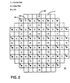
- Figure 2 is a schematic cross section of the core of the pressurized water reactor shown in Figure 1.
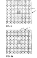
- Figure 3 is a diagram schematically illustrating a pattern of curvature indices in accordance with the invention produced by a dropped control rod.
- Figure 4A is a diagram similar to Figure 3 contrasting a pattern of curvature indices produced by a failed thermocouple.
- Figure 4B is a reiteration of Figure 4A in which the curvature indices have been recalculated ignoring the suspected failed thermocouple.
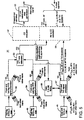
- Figure 5 is a block diagram of one of four trains of a system for automatically blocking withdrawal of the control rods from the pressurized water reactor of Figure 1 upon detection of a dropped rod.
- Figure 6 is a block diagram illustrating integration of the multiple trains for blocking rod withdrawal in accordance with the invention.
- Figure 7 is a block diagram illustrating generation of reference signals for each of the trains shown in Figure 5.
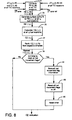
- Figure 8 is a flow chart for the relative power deviation (RD) and curvature indices (CI) calculator for the train shown in Figure 5.
- Figures 9A-9C illustrate a flow chart for the CI evaluator for the train shown in Figure 5.
- Figure 10 is an insert for the flow chart of Figure 9.
- Figures 11A and B illustrate a flow chart for a rod movement analyzer which forms part of the train of Figure 5.
- FIG. 1 is a schematic representation of a nuclear steam supply system 1 incorporating a typical pressurized water reactor (PWR) 3 in which the present invention is implemented to detect dropped control rods and malfunctioning thermocouples.
- the PWR 3 includes a reactor vessel 5 which forms a pressurized container when sealed by a head assembly 7.
- the reactor vessel 5 houses a reactor core 9 made up of a matrix of fuel assemblies 11.
- the fuel assemblies in turn contain a number of fuel rods 13 containing fissionable material. Fission reactions within the fuel rods 13 generate heat which is absorbed by a pressurized reactor coolant, for example light water, which is passed through the core 9.
- the reactor coolant enters the vessel 5 through inlet 15 and flows downward through an annular down-comer 17 and then upward through the fuel assemblies 11 where it is heated by the heat of the fission reactions.
- the heated reactor coolant flows upward out of the reactor core and through an outlet 19 into the hot leg 21 of a primary loop 23.
- the hot leg 21 delivers the heated reactor coolant to a steam generator 25 where feed water is converted into steam which is circulated in a secondary loop 27 to drive a turbine-generator 29 which generates electric power.
- Reactor coolant is returned to the inlet 15 through a cold leg 31 by a reactor coolant pump 33.
- Only one steam generator 25 in one primary loop 23 is shown in Figure 1 for clarity; however, as is known, the typical PWR nuclear steam supply system 1 has two to four primary loops, each with its own steam generator 25 generating steam, and a comparable number of secondary loops 27 driving the single turbine-generator 29.
- the reactivity of the reactor core 9 is controlled by regulation of the concentration of a neutron absorber dissolved in the reactor coolant by a reactor chemical and volume control system CVCS 34 and by control rods 35 which are inserted into and withdrawn from the reactor core 9 by a rod control system 37 as discussed above.
- the rod control system 37 inserts and withdraws banks of control rods under the direction of a reactor control and protection system 39.
- Inputs to the reactor control and protection system 39 include hot and cold leg reactor coolant temperatures measured by temperature sensors such as RTDs 41 and 43, respectively. Additional monitored reactor parameters include core exit temperatures measured at selected fuel assemblies as discussed below by core exit thermocouples 45.
- An in-core detector system 47 maps power distribution in the core on a periodic basis.
- the dropped rod detection system 49 utilizes the signals generated by the hot leg and cold leg temperature sensors 41 and 43 and the core exit thermocouples 45 to detect a dropped control rod 35 and generate a signal which is applied to the rod control system 37 to block the withdrawal of control rods.
- the exemplary PWR 3 is an advanced system which, as discussed previously, is designed to load follow primarily through movement of the control rods rather than through regulation of the concentration of neutron absorber in the reactor coolant.
- Such reactors have in addition to control rods containing neutron absorbing material, gray rods with more moderate neutron absorbing materials which are provided to maintain appropriate power distribution in the core 9.
- Figure 2 illustrates the arrangement of fuel assemblies 11 in the reactor core 9 of the exemplary PWR 3 with the conventional rods 35 depicted by the letter C, and the gray rods 35' indicated by the letter G.
- references to control rods 35 will include both the conventional control rods (C) and the gray rods (G) unless otherwise specified.
- control rods 35 in a single fuel assembly form a cluster operated by a common mechanism, while groups of clusters are ganged together electrically to form banks of control rods, as is well known.
- the arrangement of the control rods into banks is not specified in Figure 2 as it is not necessary to an understanding of the invention.
- the core exit thermocouples 45 are mounted in instrumentation thimbles provided in about a quarter of the fuel assemblies 11. As illustrated in Figure 2, the core exit thermocouples are distributed in a regular pattern across the fuel assemblies 11 so that core exit thermocouples 45 are located in fuel assemblies that are laterally adjacent to every one of the conventional control rods clusters C and all but two of the gray rod clusters G. The only exceptions are two gray rod clusters G on the periphery of the core 9, each of which has one core exit thermocouple in a laterally adjacent fuel assembly. In addition, there are at least two, and more commonly, four core exit thermocouples 45 in fuel assemblies located a chess knight's move from each control rod C and gray rod cluster G location.
- thermocouples a system divided into two completely independent trains of core exit thermocouples can readily be supported.
- the preferred embodiment of the invention adopts a four train system which requires an internal mutual exchange of information among the trains at one point in the computational process.
- the exemplary PWR 3 utilizes single core exist thermocouples distributed in four trains in the pattern indicated by the numerals 1-4 next to the thermocouples 45 in Figure 2.
- the entire system including the core exit thermocouples 45, must be certifiable as meeting full Class IEEE-603 standards.
- thermocouples 45 The temperatures measured by thermocouples 45 are determined primarily by the power distribution. When thermocouple readings exhibit sudden changes, they may be caused by either: (a) a sudden change in the core condition; or (b) thermocouple malfunctions. In the former case, the thermocouple readings change and their spatial distribution must be governed by physical principles. However, in the latter case, a controlling physical principle is not applicable. In order to simplify the evaluation between these possibilities, a new parameter is introduced, the Relative Power Deviation, RD, which is defined by: where:
- RD values are defined herein in terms of temperature, the definitions could also be cast in terms of enthalpy.
- RD can be calculated by Eq. 1 only for those fuel assemblies 11 having core exit thermocouples
- RD values for all fuel assemblies can be interpolated through use of a surface spline fit, as is well known in the art.
- Each thermocouple 45 measures an assembly exit temperature, which defines a temperature rise with respect to the inlet temperature.
- RD represents the percent change in the normalized power distribution, with respect to the reference shape. It is important to note that if the power spatial distribution is unchanged, RD remains at the value zero, regardless of power level.
- RD values become non-zero.
- the spatial distribution of RD is governed by the neutron diffusion equation.
- RD also changes by a large amount; however, its spatial variation is smooth, except at the rod insertion location. This is similar to the behavior of the neutron flux distribution.
- Curvature Index CI
- CI approximates the negative of the spatial second derivative of RD.
- thermocouple When looking for "bad thermocouple” signatures, the most meaningful CI values are those found in the location of the suspect thermocouple and in the four laterally adjacent fuel locations.
- the characteristics of a "bad thermocouple” signature are:
- Important keys to the signature differentiation process are two: (1) is the maximum CI value at a thermocouple location or on a control rod/grey rod location? If at a control rod/grey rod location, almost certainly the rod has moved. (2) if the maximum CI value is at a thermocouple location, reprocessing the RD fit and CI evaluation with the suspect RD value discarded will show a recognizable change in the CI values at laterally adjacent fuel assembly locations.
- FIGS 3, and 4A and 4B which plot the values of CI for the fuel assemblies in the vicinity of a dropped rod, and in the vicinity of a failed thermocouple respectively.
- Each (-) and (+) represent an arbitrary unit of CI, while the dots represent partial units of random sign.
- FIG 3 there is a large negative CI at the location of a dropped rod in the center of the figure in the fuel assembly 11 outlined in heavy line. It will be noticed that the CI's in the laterally and diagonally adjacent fuel assemblies are of either sign and are much smaller in magnitude than the CI of the assembly with the dropped rod.
- FIG. 4A illustrates the distribution of CI values calculated from RD values generated from a surface spline fit in which the RD value for the suspect thermocouple is given a high lack of confidence factor. As can be seen, only very small disturbances even at the location of the suspect thermocouple are indicate. Again, the disturbances only extend to the four laterally adjacent fuel assembly locations.
- FIG. 5 is a block diagram of one of four trains 51 of the dropped rod detector system 49.
- the illustrated train 51 of the dropped rod detector system 49 includes a front end hot leg RTD signal processor 53.
- This processor digitizes ohm signals received from the hot leg RTD's 41 (typically three) in the train and converts the digital ohm signals to degrees Celsius (respectively Fahrenheit).
- the processor 53 then generates an average T hot temperature for the train. This average temperature T hot , is sent to all of the other trains.
- the processor 53 receives the average hot leg temperatures T hot generated by all of the other trains and generates therefrom an average, average T hot signal.
- Each train 51 also includes a front end cold leg RTD signal processor 54 which similarly digitizes ohm signals from the cold leg RTDs 43 in the train and converts them to degrees Celsius (respectively Fahrenheit).
- the processor 54 then generates train average T cold signal which is sent to all of the other trains.
- the processor 54 then generates an average, average cold leg temperature T cold from the T cold signals from all of the trains.
- a calculator 55 generates from the T hot and T cold signals a ⁇ T core signal which is the average temperature rise across the core.
- the train 51 also includes a front end thermocouple (TC) signal processor 57 which, when the train is in service, digitizes voltage signals generated at each of the thermocouples in the train having coordinates L,M and converts them from milli-volts to degrees Celsius (respectively Fahrenheit).
- the T/C signal processor 57 also identifies obviously failed thermocouples, both failed open and failed closed.
- the processor 57 sets a lack of confidence, or tolerance, factor C (L,M) used in the surface spline fit to a large value (approximately 1,000, for example).
- the lack of confidence factor C smooths out the surface spline fit by allowing the surface generated to deviate at a data point by an amount which is a function of the magnitude of the lack of confidence factor C at that point.
- the T/C signal processor 57 computes for each thermocouple a ⁇ T T/c ( L,M ) which is the difference between the thermocouple reading and the average inlet temperature reading, T cold , provided by the processor 54. These ⁇ T T/c ( L,M ) values and C (L,M) values for the train are sent to all the other trains. Similarly, the processor 57 receives the same values from the other trains and outputs all of them to an RD and CI calculator 59.
- the front end T/C signal processor 57 sets all the ⁇ T T/c ( L,M ) in the train to ⁇ T core .
- all C (L,M) in the train are set to a large value (approximately 1,000). Again, these values are sent to all the other trains and the corresponding values from all the other trains are received to generate a complete set of values which is sent to the calculator 59.
- RD and CI calculator 59 utilizes the ⁇ T T/C and C signals from the T/C signal processor 57 and the ⁇ T core from the calculator 55 together with reference values for ⁇ T T/C and ⁇ T core to generate the CI values for all of the fuel assemblies 11 which are then used by a CI evaluator 61 which identifies any dropped rods.
- the dropped rod signal is applied to a safety system grade rod withdrawal stop generation module 63 which generates a rod stop signal for the train.
- the CI evaluator 61 also identifies failed thermocouples.
- the front end processor 57 in effect, throws out obviously failed thermocouples by setting their C values to a large number. As a result, the CI evaluator will essentially ignore such thermocouples and concentrate on the questionable thermocouples. This would include those which are not completely failed but are unreliable.
- the identification of malfunctioning thermocouples is stored in a library 65 together with the large C values for such failed thermocouples.
- the library 65 also stores the identification of failed thermocouples detected by the processor 57.
- the structure 51 illustrated in Figure 5 is provided for each of the four trains of the dropped rod protection system.
- the rod stop signals generated by the stop generators 63-1 to 63-4 for each of the four trains is input to voting logic 67 which, as is well known in the art, generates a block rod withdrawal signal in the presence of a selected combination of train rod stop signals such as, for example, two out of four, or if one train is out of service, two out of three.
- the block rod withdrawal signal is applied to the rod control system 37 to prevent withdrawal of the control rods in response to a dropped rod.
- a common reference transmitter 69 provides ⁇ T core/REF and ⁇ T T/C (L,M) REF values for all thermocouple locations to each of the four trains of the dropped rod protection system.
- maps of the CI values across the core will show progressively greater symmetric distortion, reflecting the deviation of the current rod configuration from that under which reference conditions were established. This is perfectly normal, but none the less highly confusing to a computer. Accordingly, it is highly desirable to periodically update the reference values of ⁇ T core/REF and ⁇ T T/C (L,M) REF .
- These references values are updated, utilizing a software core surveillance program such as BEACON, which is typically run at, for example, 15 minute intervals.
- BEACON which is available from Westinghouse Commercial Nuclear Fuels Divisions, is an analytical tool which calculates a three dimensional nodal power distribution in the core utilizing either excore power range detectors and core exit thermocouples or fixed incore detectors. Since the reference transmitter 69, and BEACON which interfaces with it, are not safety system grade, the reference signals provided by the reference transmitters 69 are subject to human approval as shown functionally by the switch 71 in Figure 5. If there is reason for the operator to believe that the reference values are not valid, approval of the reference values can be withheld. Also, as discussed in connection with Figure 11 below, updating of the references can be prevented by a block indicated at 70 when misalignment of a control rod is detected.
- a method for updating the reference values is to (a) monitor the CI values at symmetric control rod locations of the controlling groups. These values will steadily increase in absolute magnitude as the control rods are moved farther and farther from the positions they were at when the last reference set of values was established. (b) when the monitored CI values reach a preselected absolute magnitude, display to the operator the bank position that corresponded to the still current reference values and an indication of the net direction of bank movement from that position. The operator must then attempt to confirm, using the rod position indicators, that the dropped rod protection septum has successfully tracked the trend of control bank movement. If no alarms to the contrary exist and if he is satisfied that the protection system is at least trending properly, he must authorize replacing the set of reference values that had been in use with the current set of those parameters.
- the key ingredient here is the operator's verification that the system is apparently working correctly. (c) if one of the "anomalous train behavior" or anomalous rod/bank movement type alarms is generated, an update "block” is activated and the current values can not be made reference values. If the operator is not satisfied that the system is trending properly he must withhold approval to update the reference values. In either event, and assuming that any system malfunctions have been corrected, the operator must verify that the BEACON core surveillance system is running correctly, i.e., no significant differences exist between various measurable aspects of core power distribution such as incore detector signals and the equivalent analytically predicted values.
- BEACON If BEACON is seen to be generating a reliable estimate of core power distribution, the operator can authorize the current BEACON estimates of ⁇ T core and ⁇ T T/C for all thermocouples to be established as the new set of reference values for the dropped rod protection system. Since BEACON runs continuously on-line it is always current with core operations. (d) if the reference values cannot be updated when needed, administrative controls, such as setting very conservative rod insertion limits to insure that the core will survive one or more dropped rods without damage, must be imposed until the situation is corrected.
- Figure 8 illustrates a flow chart for the RD and CI calculator 59.
- the calculator 59 computes RD (L,M) at all thermocouple locations using equation 1 as indicated at 71.
- RD RD
- a surface spline fit is used at 73 to generate the relative power deviation RD for all fuel assemblies (i,j).
- These values are then used to calculate the curvature indices CI (i,j) for all fuel assemblies 11 using equation 2 as indicated at 75.
- the curvature indices are then ranked by magnitude at 77.
- the system also detects normal movement of the control rods. Periodically, such as for example, every 10 minutes, as determined at 79, the status of flags indicating rod movement is stored at 81, the flags are reset at 83 and a timer for the period is reset at 85.
- the flow chart for the CI evaluator 61 is shown in Figures 9A-9C with an insert which is Figure 10.
- the CI evaluator cycles through the ranked CIs in descending absolute order as indicated at 87. Only those absolute CI values which are greater than a first limit as determined at 89 are examined. This limit 1 is selected so that only signals above the expected noise level need be examined.
- the CI evaluator is exited and the program transfers to the rod movement analyzer shown in Figures 11A and 11B. If the evaluator cycles through all of the CIs, indicating that all of the CIs are above the first limit, which is not a valid condition, "an anomalous train behavior" alarm is generated at 91.
- the CI evaluator For those CI signals above the noise level at locations (i, j) at which there are thermocouples as determined at 93, the CI evaluator performs the routine shown in Figure 10 which checks for a malfunctioning thermocouple at the cited location by eliminating the reading from the thermocouple.
- the current lack of confidence factor C for the thermocouple in question, and the current curvature index CI array calculated with that thermocouple value are stored at 97 and 99, respectively.
- the lack of confidence factor C for the thermocouple in question is then set to a high value at 101 and the surface spline fit for RD at all fuel assembly locations is regenerated at 103.
- the new RD values are then used at 105 to recalculate the CIs.
- thermocouple signature is detected at 107, the originally stored values of C and the CI array are restored at 109 and 111 and the program returns to Figure 9A at the "yes" branch from the insert.
- thermocouple signature If a bad thermocouple signature is not detected at 107, the C value for the location under examination and the original CI array are restored at 113 and 115 and the program returns to Figure 9A and the "no" branch from the insert.
- the CIs in the region surrounding this fuel assembly are examined at 127 to determine if they show a moved rod signature. If they do, the absolute value of the CI is examined at 129 in Figure 9C to determine whether it is compatible with normal control rod movement or a dropped rod. As soon as a dropped rod is detected, a safety system grade rod withdrawal stop signal is generated at 131 and transmitted to the rod control system at 133 and a "rod withdrawal stop actuated" alarm is generated at 135.
- a rod movement flag for the rod at the coordinates R,S is set at 137. This flag contains the CI value and rod group assignment. The program then loops back to Figure 9A to examine the next fuel assembly location.
- FIGS 11A and 11B illustrate the flowchart for the rod movement analyzer.
- this routine is called to analyze detected rod movements. This is done by cycling through the rod banks in the order of insertion sequence as indicated at 143 in Figure 11A to determine if there are any flags set indicating a movement of a control rod in the bank as indicated at 145. If only one rod movement flag is set in the bank as determined at 147, then an "apparent misalignment of rod (R,S) in bank X" message is generated at 149 and the "reference update" block is set at 151. This prevents changing of the references at 70 in Figure 7. If the movement of more than one but not all of the rods in the bank have been detected at 153, then an "anomalous movement of bank X rods" message is generated at 155.
- the current rod movement flag data is compared on a rod by rod basis with the stored data on that bank. If recent bank movement is indicated at 159 in Figure 11B and that movement is indicated as being a withdrawal at 161, a "bank X withdrawn during last minutes" message is generated at 163. For a rod insertion, a corresponding message is generated at 165.
- the rod movement analyzer does not provide precise information on rod movement, but rather, provides an indication of which rods have moved and in which direction which can be compared with the rod position indicator system.
- the rod analyzer functions primarily serve as a confidence builder for the operator by providing information on rod movement which can be cross-checked against other systems to provide an indication of the reliability of the system.
Landscapes
- Physics & Mathematics (AREA)
- Engineering & Computer Science (AREA)
- Plasma & Fusion (AREA)
- General Engineering & Computer Science (AREA)
- High Energy & Nuclear Physics (AREA)
- Chemical & Material Sciences (AREA)
- Chemical Kinetics & Catalysis (AREA)
- Monitoring And Testing Of Nuclear Reactors (AREA)
Claims (17)
- Réacteur à eau sous pression (3), qui comprend :caractérisé en ce que les moyens (49) détectant la barre qui a chuté comprennent des capteurs de température (45) produisant des signaux de température représentatifs de la température du caloporteur qui sort d'assemblages combustibles (11) choisis, répartis dans ledit coeur de réacteur, et un moyen (51) qui réagit auxdits signaux de température pour reconnaítre la barre de contrôle ayant chuté et produire un signal d'arrêt, et dans lequel ledit moyen (37) de commande des barres réagit audit signal d'arrêt en empêchant le retrait desdites barres de contrôle (35) hors dudit coeur de réacteur (9).un coeur de réacteur (9) contenant une pluralité d'assemblages combustibles (11),des moyens (33) faisant circuler un caloporteur à travers lesdits assemblages combustibles dudit coeur de réacteur,des barres de contrôle (35) pouvant être insérées dans ledit coeur de réacteur (9);un moyen (37) de commande des barres servant à insérer et extraire automatiquement certaines au moins desdites barres de contrôle (35) dans ledit coeur de réacteur (9) et hors de celui-ci, etdes moyens (49) détectant une barre de contrôle ayant chuté et empêchant automatiquement ledit moyen (37) de commande des barres d'extraire les barres de contrôle (35) du coeur de réacteur (9) quand une barre ayant chuté a été détectée,
- Réacteur à eau sous pression selon la revendication 1, dans lequel lesdits capteurs de température (45) comprennent des thermocouples, dans lequel ledit moyen (51) qui réagit auxdits signaux de température pour reconnaítre une barre de contrôle ayant chuté comprend un moyen (61) qui réagit auxdits signaux de température pour faire la différence entre un thermocouple fonctionnant mal et la chute d'une barre de contrôle et produire un signal d'arrêt uniquement en réponse à la chute d'une barre de contrôle.
- Réacteur à eau sous pression selon la revendication 1, dans lequel lesdits moyens (49) détectant la chute d'une barre de contrôle comprennent en outre des moyens (41, 43, 55) qui déterminent une variation moyenne de la température du caloporteur traversant le coeur du réacteur, un moyen (59) qui détermine un écart relatif de puissance pour lesdits assemblages combustibles à partir desdits signaux de température et de ladite variation moyenne de la température, et des moyens (75-129) qui traitent lesdits écarts relatifs de puissance pour détecter la barre de contrôle qui a chuté.
- Réacteur à eau sous pression selon la revendication 3, dans lequel lesdits moyens (75-129) qui traitent lesdits écarts relatifs de puissance comprennent un moyen (75) qui produit pour lesdits assemblages combustibles des indices de courbure représentatifs de la dérivée spatiale seconde desdites variations relatives de température et des moyens (77-129) qui reconnaissent la barre de contrôle ayant chuté à partir desdits indices de courbure.
- Réacteur à eau sous pression selon la revendication 4, dans lequel lesdits capteurs de température (45) comprennent des thermocouples, et dans lequel lesdits moyens de reconnaissance (77-129) analysent lesdits indices de courbure des assemblages combustibles au niveau desdits thermocouples et près de ceux-ci pour identifier un thermocouple qui fonctionne mal.
- Réacteur à eau sous pression selon la revendication 5, dans lequel lesdits moyens (49) détectant la chute d'une barre de contrôle sont divisés en multiples trains (51), chaque train comprenant certains desdits thermocouples (45) répartis dans ledit coeur du réacteur (9), un moyen (57) qui détermine ladite variation relative de température, un moyen (59) qui produit lesdits indices de courbure et un moyen (61) qui analyse lesdits indices de courbure et produit séparément pour ledit train un signal d'arrêt de barre, et dans lequel ledit moyen (49) de commande des barres réagit auxdits signaux d'arrêt de barre provenant de chaque train et empêche le retrait desdites barres de contrôle par une logique sélective (67) appliquée auxdits signaux d'arrêt.
- Réacteur à eau sous pression selon la revendication 5, dans lequel ledit moyen (59) produisant lesdits indices de courbure compense automatiquement un thermocouple fonctionnant mal qui est détecté par ledit moyen d'analyse.
- Procédé de protection d'un réacteur à eau sous pression (3) comprenant un coeur de réacteur (9) qui contient des assemblages combustibles (11) à travers lesquels un caloporteur est mis en circulation d'une branche froide (31) à une branche chaude (21), ledit procédé comprenant les étapes consistant à :placer des thermocouples (45) de sortie de coeur, qualifiés pour les systèmes de protection, au niveau d'assemblages combustibles sélectionnés (11) dans ledit coeur de réacteur (9),mesurer automatiquement les températures de sortie de coeur au niveau desdits assemblages combustibles sélectionnés (11) où sont situés lesdits thermocouples (45) de sortie de coeur qualifiés pour les systèmes de protection,mesurer automatiquement des températures moyennes d'entrée et de sortie de coeur avec des capteurs de température (43, 51), qualifiés pour les systèmes de protection et situés au niveau de ladite branche chaude et de ladite branche froide,analyser automatiquement, à l'aide d'un analyseur qualifié pour les systèmes de protection, ledit ensemble de températures de sortie et lesdites températures moyennes d'entrée et de sortie de coeur pour identifier une barre de contrôle (35) ayant chuté, etempêcher automatiquement, à l'aide d'un moyen (63) qualifié pour les systèmes de protection, le retrait des barres de contrôle (35) hors dudit coeur de réacteur (9) quand la barre ayant chuté est identifiée.
- Procédé selon la revendication 8, dans lequel ladite étape d'analyse comprend :le calcul automatique d'un écart relatif de puissance pour chaque assemblage combustible (11) à partir desdites températures de sortie du coeur et à partir desdites températures moyennes d'entrée et de sortie du coeur,le calcul automatique d'indices de courbure pour lesdits assemblages combustibles (11) à partir desdits écarts relatifs de puissance, etla reconnaissance automatique de la barre de contrôle ayant chuté à partir desdits indices de courbure.
- Procédé selon la revendication 9, comprenant en outre une reconnaissance automatique d'un thermocouple fonctionnant mal (45) à partir desdits indices de courbure.
- Procédé selon la revendication 10, comprenant un réglage automatique dudit calcul d'écart relatif de puissance pour chaque assemblage dans le cas d'un thermocouple (45) fonctionnant mal.
- Procédé selon la revendication 9, dans lequel ledit calcul de l'écart relatif de puissance pour chaque assemblage combustible comprend l'application de la relation :dans laquelle :

- (L,M)
- position du thermocouple
- ΔT
- élévation de température dans l'assemblage complet
- ΔT0
- élévation de température dans l'assemblage complet pour une condition de référence
- ΔTavg
- élévation de température dans la cuve du réacteur
- ΔT0avg
- élévation de température dans la cuve du réacteur pour une condition de référence.
- Procédé selon la revendication 12, dans lequel ledit calcul de la courbure comprend l'application de la relation :
- Procédé selon la revendication 12, comprenant une ré-actualisation périodique de ladite élévation de température dans l'assemblage combustible (11) et de ladite élévation de température dans ledit coeur (9) pour des conditions de référence.
- Procédé selon la revendication 14, dans lequel ladite ré-actualisation périodique comprend l'utilisation de cartes de coeur produites par un système (47) de détection en-coeur.
- Procédé selon la revendication 15, dans lequel ladite ré-actualisation périodique comprend une détermination analytique périodique qui utilise des cartes de coeur produites par un système (47) de détection en-coeur.
- Procédé selon la revendication 14, dans lequel ladite réactualisation périodique comprend le suivi d'une tendance dans le mouvement des barres de contrôle à partir desdites températures de sortie du coeur et desdites températures moyennes d'entrée et de sortie du coeur, la comparaison de ladite tendance dans le mouvement des barres de contrôle avec une position des barres de contrôle déterminée de manière indépendante et, lorsque ladite tendance dans le mouvement des barres de contrôle est sensiblement confirmée par ladite position des barres de contrôle déterminée de manière indépendante, une ré-actualisation de ladite élévation de température dans l'assemblage combustible pour une condition de référence et de ladite élévation de température dans la cuve (5) du réacteur pour une condition de référence afin de les mettre au niveau des valeurs actuelles de ladite élévation de température dans l'assemblage combustible (11) et de ladite élévation de température dans la cuve (5) du réacteur.
Applications Claiming Priority (2)
| Application Number | Priority Date | Filing Date | Title |
|---|---|---|---|
| US08/067,280 US5297174A (en) | 1993-05-26 | 1993-05-26 | Safety system grade apparatus and method for detecting a dropped control rod and malfunctioning exit thermocouples in a pressurized water reactor |
| US67280 | 1998-04-27 |
Publications (2)
| Publication Number | Publication Date |
|---|---|
| EP0626698A1 EP0626698A1 (fr) | 1994-11-30 |
| EP0626698B1 true EP0626698B1 (fr) | 1998-01-14 |
Family
ID=22074937
Family Applications (1)
| Application Number | Title | Priority Date | Filing Date |
|---|---|---|---|
| EP94303746A Expired - Lifetime EP0626698B1 (fr) | 1993-05-26 | 1994-05-25 | Appareillage ayant un niveau de sûureté et méthode de détection d'une barre chutée et d'un mauvais fonctionnement dans la réponse des thermocouples, dans un réacteur à eau pressurisée |
Country Status (7)
| Country | Link |
|---|---|
| US (2) | US5297174A (fr) |
| EP (1) | EP0626698B1 (fr) |
| JP (1) | JP2912545B2 (fr) |
| KR (1) | KR100333206B1 (fr) |
| CZ (1) | CZ119394A3 (fr) |
| ES (1) | ES2111854T3 (fr) |
| SK (1) | SK281872B6 (fr) |
Families Citing this family (13)
| Publication number | Priority date | Publication date | Assignee | Title |
|---|---|---|---|---|
| US5745538A (en) * | 1995-10-05 | 1998-04-28 | Westinghouse Electric Corporation | Self-powered fixed incore detector |
| US7596198B1 (en) | 2005-04-01 | 2009-09-29 | Westinghouse Electric Co Llc | Over temperature and over power delta temperature operating margin recovery method and reactor system employing the same |
| US7845223B2 (en) * | 2005-09-08 | 2010-12-07 | General Electric Company | Condensing chamber design |
| JP4585527B2 (ja) * | 2006-03-02 | 2010-11-24 | ウエスチングハウス・エレクトリック・カンパニー・エルエルシー | 原子炉システムのトリップ制御方法及び原子炉システム |
| FR2953318B1 (fr) * | 2009-11-30 | 2011-12-09 | Areva Np | Procede et dispositif de detection de chute de grappe d'un reacteur nucleaire |
| US8767903B2 (en) * | 2011-01-07 | 2014-07-01 | Westinghouse Electric Company Llc | Wireless in-core neutron monitor |
| CN102682862B (zh) * | 2012-05-25 | 2015-03-04 | 中国核动力研究设计院 | 压水堆核电站堆芯热电偶有效性状态在线诊断方法 |
| US9208907B2 (en) | 2012-11-13 | 2015-12-08 | Westinghouse Electric Company Llc | Method of validating nuclear reactor in-vessel detector output signals |
| CN106935291B (zh) * | 2015-12-30 | 2018-07-27 | 江苏核电有限公司 | 一种燃料组件变形量双层测量系统及测量方法 |
| JP6362804B1 (ja) * | 2018-02-28 | 2018-07-25 | 三菱重工業株式会社 | 原子力設備の制御装置及び原子力設備の制御方法 |
| FR3084958B1 (fr) * | 2018-08-09 | 2020-10-23 | Framatome Sa | Procede de limitation de fonctionnement d'un reacteur nucleaire |
| CN112632873B (zh) * | 2020-12-30 | 2022-10-28 | 西安交通大学 | 一种核反应堆热腿测温热电偶测点位置布置方式确定方法 |
| CN113871037A (zh) * | 2021-09-14 | 2021-12-31 | 中广核研究院有限公司 | 反应堆的运行控制方法、装置、计算机设备和存储介质 |
Family Cites Families (12)
| Publication number | Priority date | Publication date | Assignee | Title |
|---|---|---|---|---|
| US4399095A (en) * | 1977-12-16 | 1983-08-16 | Westinghouse Electric Corp. | Protection and control system for a nuclear reactor |
| JPS57139693A (en) * | 1981-02-23 | 1982-08-28 | Mitsubishi Atomic Power Ind | Method and device for protecting core at control rod drop |
| US4637910A (en) * | 1984-01-20 | 1987-01-20 | Westinghouse Electric Corp. | Method and apparatus for continuous on-line synthesis of power distribution in a nuclear reactor core |
| US4699749A (en) * | 1985-05-07 | 1987-10-13 | Westinghouse Electric Corp. | Controlling a nuclear reactor with dropped control rods |
| US4716009A (en) * | 1985-12-17 | 1987-12-29 | Westinghouse Electric Corp. | Dropped rod protection insensitive to large load loss |
| US4774050A (en) * | 1986-04-10 | 1988-09-27 | Westinghouse Electric Corp. | Axial power distribution monitor and display using outputs from ex-core detectors and thermocouples |
| US4774049A (en) * | 1986-04-10 | 1988-09-27 | Westinghouse Electric Corp. | Two and three dimensional core power distribution monitor and display |
| FR2632761B1 (fr) * | 1988-06-08 | 1990-08-17 | Framatome Sa | Procede et dispositif de detection de la chute d'une grappe de controle d'un reacteur nucleaire |
| US4927594A (en) * | 1988-08-10 | 1990-05-22 | Westinghouse Electric Corp. | Thermocouple based control rod position indication system |
| US5006301A (en) * | 1989-03-22 | 1991-04-09 | Joyner Engineers And Trainers, Inc. | Method and apparatus for control rod drop monitoring |
| US4965040A (en) * | 1989-04-13 | 1990-10-23 | The Babcock & Wilcox Company | Maximum/minimum asymmetric rod detection |
| FR2656415B1 (fr) * | 1989-12-27 | 1993-04-09 | Framatome Sa | Procede et dispositif de mesure simultanee de distance entre tubes metalliques et d'epaisseur d'oxyde sur les tubes. |
-
1993
- 1993-05-26 US US08/067,280 patent/US5297174A/en not_active Expired - Lifetime
-
1994
- 1994-01-19 US US08/183,393 patent/US5373539A/en not_active Expired - Fee Related
- 1994-05-16 CZ CZ941193A patent/CZ119394A3/cs unknown
- 1994-05-25 EP EP94303746A patent/EP0626698B1/fr not_active Expired - Lifetime
- 1994-05-25 KR KR1019940011340A patent/KR100333206B1/ko not_active Expired - Lifetime
- 1994-05-25 SK SK617-94A patent/SK281872B6/sk unknown
- 1994-05-25 ES ES94303746T patent/ES2111854T3/es not_active Expired - Lifetime
- 1994-05-25 JP JP6111418A patent/JP2912545B2/ja not_active Expired - Lifetime
Also Published As
| Publication number | Publication date |
|---|---|
| US5297174A (en) | 1994-03-22 |
| SK281872B6 (sk) | 2001-08-06 |
| EP0626698A1 (fr) | 1994-11-30 |
| ES2111854T3 (es) | 1998-03-16 |
| KR100333206B1 (ko) | 2002-10-18 |
| KR940026975A (ko) | 1994-12-10 |
| US5373539A (en) | 1994-12-13 |
| CZ119394A3 (en) | 1994-12-15 |
| JPH07113895A (ja) | 1995-05-02 |
| SK61794A3 (en) | 1995-01-12 |
| JP2912545B2 (ja) | 1999-06-28 |
Similar Documents
| Publication | Publication Date | Title |
|---|---|---|
| US5091139A (en) | Automated thermal limit monitor | |
| EP0626698B1 (fr) | Appareillage ayant un niveau de sûureté et méthode de détection d'une barre chutée et d'un mauvais fonctionnement dans la réponse des thermocouples, dans un réacteur à eau pressurisée | |
| US4080251A (en) | Apparatus and method for controlling a nuclear reactor | |
| US5586156A (en) | Reactor protection system with automatic self-testing and diagnostic | |
| KR950013236B1 (ko) | 상대 엔탈피의 프로파일을 표시하는 센서감시장치 및 방법 | |
| KR910008358B1 (ko) | 원자로심의 출력 분포를 연속 온 -라인으로 감시하기 위한 방법 및 장치 | |
| WO1997004463A1 (fr) | Systeme de protection de reacteur | |
| Zhao | An integrated approach to performance monitoring and fault diagnosis of nuclear power systems | |
| Deyst et al. | Sensor validation: a method to enhance the quality of the man/machine interface in nuclear power stations | |
| Kumar et al. | Reliability analysis of shutdown system | |
| O'Brien et al. | Protection systems | |
| Kafka et al. | Intelligent decision aids for abnormal events in nuclear power plants | |
| Swaminathan et al. | ’’Computer based core monitoring system” | |
| Girard et al. | Core parameter monitoring on French LMFBR: Requirements, current design and new trends | |
| Ridolfo et al. | The Nuplex 80+™ advanced control complex from ABB Combustion Engineering | |
| Yastrebenetsky et al. | NPP I&C Systems: General Provisions | |
| Weisman | Uncertainty and risk in nuclear power plant design | |
| Hanson et al. | Assessing information needs and instrument availability for a pressurized water reactor during severe accidents | |
| Yu | Instrumentation and Control System | |
| Endrizzi et al. | REFINEMENT OF SIEMENS CORE MONITORING BASED ON AEROBALL AND PDD IN-CORE MEASURING SYSTEMS USING POWERTRAX | |
| Trapp et al. | Computerized reactor surveillance and control system: An FBR example | |
| Glasstone et al. | Plant Operations | |
| Bevilacqua et al. | Application of Digital Computer Systems in Nuclear Power Plants | |
| Board | Core management and fuel handling in operation of pressurised heavy water reactors | |
| Casada et al. | Operating experiences and degradation detection for auxiliary feedwater systems |
Legal Events
| Date | Code | Title | Description |
|---|---|---|---|
| PUAI | Public reference made under article 153(3) epc to a published international application that has entered the european phase |
Free format text: ORIGINAL CODE: 0009012 |
|
| AK | Designated contracting states |
Kind code of ref document: A1 Designated state(s): ES FR IT |
|
| 17P | Request for examination filed |
Effective date: 19950530 |
|
| 17Q | First examination report despatched |
Effective date: 19960314 |
|
| GRAG | Despatch of communication of intention to grant |
Free format text: ORIGINAL CODE: EPIDOS AGRA |
|
| GRAH | Despatch of communication of intention to grant a patent |
Free format text: ORIGINAL CODE: EPIDOS IGRA |
|
| GRAH | Despatch of communication of intention to grant a patent |
Free format text: ORIGINAL CODE: EPIDOS IGRA |
|
| GRAA | (expected) grant |
Free format text: ORIGINAL CODE: 0009210 |
|
| AK | Designated contracting states |
Kind code of ref document: B1 Designated state(s): ES FR IT |
|
| ET | Fr: translation filed | ||
| REG | Reference to a national code |
Ref country code: ES Ref legal event code: FG2A Ref document number: 2111854 Country of ref document: ES Kind code of ref document: T3 |
|
| ITF | It: translation for a ep patent filed | ||
| PLBE | No opposition filed within time limit |
Free format text: ORIGINAL CODE: 0009261 |
|
| STAA | Information on the status of an ep patent application or granted ep patent |
Free format text: STATUS: NO OPPOSITION FILED WITHIN TIME LIMIT |
|
| 26N | No opposition filed | ||
| PGFP | Annual fee paid to national office [announced via postgrant information from national office to epo] |
Ref country code: ES Payment date: 20020517 Year of fee payment: 9 |
|
| PG25 | Lapsed in a contracting state [announced via postgrant information from national office to epo] |
Ref country code: ES Free format text: LAPSE BECAUSE OF NON-PAYMENT OF DUE FEES Effective date: 20030526 |
|
| REG | Reference to a national code |
Ref country code: ES Ref legal event code: FD2A Effective date: 20030526 |
|
| PGFP | Annual fee paid to national office [announced via postgrant information from national office to epo] |
Ref country code: IT Payment date: 20130520 Year of fee payment: 20 Ref country code: FR Payment date: 20130531 Year of fee payment: 20 |