EP0626737A2 - Connecteur - Google Patents
Connecteur Download PDFInfo
- Publication number
- EP0626737A2 EP0626737A2 EP94302405A EP94302405A EP0626737A2 EP 0626737 A2 EP0626737 A2 EP 0626737A2 EP 94302405 A EP94302405 A EP 94302405A EP 94302405 A EP94302405 A EP 94302405A EP 0626737 A2 EP0626737 A2 EP 0626737A2
- Authority
- EP
- European Patent Office
- Prior art keywords
- electrodes
- stationary
- insertion side
- connector housing
- connector
- Prior art date
- Legal status (The legal status is an assumption and is not a legal conclusion. Google has not performed a legal analysis and makes no representation as to the accuracy of the status listed.)
- Granted
Links
Images




Classifications
-
- H—ELECTRICITY
- H01—ELECTRIC ELEMENTS
- H01R—ELECTRICALLY-CONDUCTIVE CONNECTIONS; STRUCTURAL ASSOCIATIONS OF A PLURALITY OF MUTUALLY-INSULATED ELECTRICAL CONNECTING ELEMENTS; COUPLING DEVICES; CURRENT COLLECTORS
- H01R13/00—Details of coupling devices of the kinds covered by groups H01R12/70 or H01R24/00 - H01R33/00
- H01R13/44—Means for preventing access to live contacts
- H01R13/447—Shutter or cover plate
- H01R13/453—Shutter or cover plate opened by engagement of counterpart
- H01R13/4532—Rotating shutter
-
- B—PERFORMING OPERATIONS; TRANSPORTING
- B60—VEHICLES IN GENERAL
- B60L—PROPULSION OF ELECTRICALLY-PROPELLED VEHICLES; SUPPLYING ELECTRIC POWER FOR AUXILIARY EQUIPMENT OF ELECTRICALLY-PROPELLED VEHICLES; ELECTRODYNAMIC BRAKE SYSTEMS FOR VEHICLES IN GENERAL; MAGNETIC SUSPENSION OR LEVITATION FOR VEHICLES; MONITORING OPERATING VARIABLES OF ELECTRICALLY-PROPELLED VEHICLES; ELECTRIC SAFETY DEVICES FOR ELECTRICALLY-PROPELLED VEHICLES
- B60L53/00—Methods of charging batteries, specially adapted for electric vehicles; Charging stations or on-board charging equipment therefor; Exchange of energy storage elements in electric vehicles
- B60L53/10—Methods of charging batteries, specially adapted for electric vehicles; Charging stations or on-board charging equipment therefor; Exchange of energy storage elements in electric vehicles characterised by the energy transfer between the charging station and the vehicle
- B60L53/14—Conductive energy transfer
- B60L53/16—Connectors, e.g. plugs or sockets, specially adapted for charging electric vehicles
-
- H—ELECTRICITY
- H01—ELECTRIC ELEMENTS
- H01R—ELECTRICALLY-CONDUCTIVE CONNECTIONS; STRUCTURAL ASSOCIATIONS OF A PLURALITY OF MUTUALLY-INSULATED ELECTRICAL CONNECTING ELEMENTS; COUPLING DEVICES; CURRENT COLLECTORS
- H01R13/00—Details of coupling devices of the kinds covered by groups H01R12/70 or H01R24/00 - H01R33/00
- H01R13/64—Means for preventing incorrect coupling
- H01R13/641—Means for preventing incorrect coupling by indicating incorrect coupling; by indicating correct or full engagement
-
- B—PERFORMING OPERATIONS; TRANSPORTING
- B60—VEHICLES IN GENERAL
- B60L—PROPULSION OF ELECTRICALLY-PROPELLED VEHICLES; SUPPLYING ELECTRIC POWER FOR AUXILIARY EQUIPMENT OF ELECTRICALLY-PROPELLED VEHICLES; ELECTRODYNAMIC BRAKE SYSTEMS FOR VEHICLES IN GENERAL; MAGNETIC SUSPENSION OR LEVITATION FOR VEHICLES; MONITORING OPERATING VARIABLES OF ELECTRICALLY-PROPELLED VEHICLES; ELECTRIC SAFETY DEVICES FOR ELECTRICALLY-PROPELLED VEHICLES
- B60L2270/00—Problem solutions or means not otherwise provided for
- B60L2270/30—Preventing theft during charging
- B60L2270/32—Preventing theft during charging of electricity
-
- B—PERFORMING OPERATIONS; TRANSPORTING
- B60—VEHICLES IN GENERAL
- B60L—PROPULSION OF ELECTRICALLY-PROPELLED VEHICLES; SUPPLYING ELECTRIC POWER FOR AUXILIARY EQUIPMENT OF ELECTRICALLY-PROPELLED VEHICLES; ELECTRODYNAMIC BRAKE SYSTEMS FOR VEHICLES IN GENERAL; MAGNETIC SUSPENSION OR LEVITATION FOR VEHICLES; MONITORING OPERATING VARIABLES OF ELECTRICALLY-PROPELLED VEHICLES; ELECTRIC SAFETY DEVICES FOR ELECTRICALLY-PROPELLED VEHICLES
- B60L2270/00—Problem solutions or means not otherwise provided for
- B60L2270/30—Preventing theft during charging
- B60L2270/34—Preventing theft during charging of parts
-
- Y—GENERAL TAGGING OF NEW TECHNOLOGICAL DEVELOPMENTS; GENERAL TAGGING OF CROSS-SECTIONAL TECHNOLOGIES SPANNING OVER SEVERAL SECTIONS OF THE IPC; TECHNICAL SUBJECTS COVERED BY FORMER USPC CROSS-REFERENCE ART COLLECTIONS [XRACs] AND DIGESTS
- Y02—TECHNOLOGIES OR APPLICATIONS FOR MITIGATION OR ADAPTATION AGAINST CLIMATE CHANGE
- Y02T—CLIMATE CHANGE MITIGATION TECHNOLOGIES RELATED TO TRANSPORTATION
- Y02T10/00—Road transport of goods or passengers
- Y02T10/60—Other road transportation technologies with climate change mitigation effect
- Y02T10/70—Energy storage systems for electromobility, e.g. batteries
-
- Y—GENERAL TAGGING OF NEW TECHNOLOGICAL DEVELOPMENTS; GENERAL TAGGING OF CROSS-SECTIONAL TECHNOLOGIES SPANNING OVER SEVERAL SECTIONS OF THE IPC; TECHNICAL SUBJECTS COVERED BY FORMER USPC CROSS-REFERENCE ART COLLECTIONS [XRACs] AND DIGESTS
- Y02—TECHNOLOGIES OR APPLICATIONS FOR MITIGATION OR ADAPTATION AGAINST CLIMATE CHANGE
- Y02T—CLIMATE CHANGE MITIGATION TECHNOLOGIES RELATED TO TRANSPORTATION
- Y02T10/00—Road transport of goods or passengers
- Y02T10/60—Other road transportation technologies with climate change mitigation effect
- Y02T10/7072—Electromobility specific charging systems or methods for batteries, ultracapacitors, supercapacitors or double-layer capacitors
-
- Y—GENERAL TAGGING OF NEW TECHNOLOGICAL DEVELOPMENTS; GENERAL TAGGING OF CROSS-SECTIONAL TECHNOLOGIES SPANNING OVER SEVERAL SECTIONS OF THE IPC; TECHNICAL SUBJECTS COVERED BY FORMER USPC CROSS-REFERENCE ART COLLECTIONS [XRACs] AND DIGESTS
- Y02—TECHNOLOGIES OR APPLICATIONS FOR MITIGATION OR ADAPTATION AGAINST CLIMATE CHANGE
- Y02T—CLIMATE CHANGE MITIGATION TECHNOLOGIES RELATED TO TRANSPORTATION
- Y02T90/00—Enabling technologies or technologies with a potential or indirect contribution to GHG emissions mitigation
- Y02T90/10—Technologies relating to charging of electric vehicles
- Y02T90/14—Plug-in electric vehicles
Definitions
- This invention relates to a connector which brings connector housings into a coupling position to thereby maintain electrical conduction between electrodes.
- connection and disconnection between the battery and a charger are effected by way of a connector.
- a connector couples a pair of connector housings to press-contact two pairs of electrodes provided in the connector housings, thereby bringing the electrodes into a state of electrical conduction.
- some connectors are provided with locking means between the connector housings.
- pairs of electrodes are brought into a conductive state while being coupled (so-called incomplete coupling position) upon coupling the connector housing.
- the pairs of electrodes are brought into a conductive state while being moved to a detaching position upon detaching the connector housings. Consequently, charging can be continued even in an incomplete coupling position caused in the case of mislocking or unlocking upon coupling the connector housings.
- the connector housings Since the connector housings are inclined to be released relatively easily in the incomplete coupling position, the connector housings under conduction of the electrodes may be disconnected on account of their own weight or an external tensile force. At that time, an arc may occur between the electrodes or a short-circuit is generated between the electrodes and another conductive parts.
- An object of the present invention is to provide a connector which can positively bring electrodes into a conductive state in a coupling position of a pair of connector housings and can inhibit the electrodes from conducting in an incomplete coupling position in which the connector housing are relatively easily disconnected.
- a connector housing of the present invention comprises: a stationary side connector housing having stationary side electrodes; an insertion side connector housing having insertion side electrodes; locking means for coupling said insertion side connector housing to said stationary side connector housing so that said insertion side electrodes are electrically coupled to said stationary side electrodes; and movable means disposed between said connector housings to move in association with movement of said locking means and having movable electrodes.
- the movable electrodes are arranged at a given position between said stationary side and insertion side electrodes to conducts a current between said electrodes upon a coupling position of said locking means and arranged away from said given position to interrupt a conduction between said electrodes upon a detaching position of said locking means.
- both connector housings are locked in the locking position by coupling the insertion side connector housing to the stationary connector housing and bringing the locking means into the coupling position.
- the movable plate provided between both connector housings is moved with the locking means and the movable electrodes moves to a position between the stationary electrodes and the insertion electrodes to effect conduction.
- the locking means are in the detaching position, the movable electrodes on the movable plate move to another position so as to prevent conduction. Accordingly, only when both connector housings are locked in the coupling position, are both electrodes brought into a conductive state and when both connector housings are in an incomplete coupling state, both electrodes are brought into a non-conductive state.
- the connector of the present invention since a pair of electrodes are brought into a conductive or non-conductive state in connection with the locking means, the electrodes are positively brought into a conductive state in the coupling position of the connector housing while the electrodes are prevented from conducting when the connector housings are relatively easily detached. Particularly, even if both connector housings happen to be changed from an incomplete to a detaching position, it is possible to prevent any electrical failure such as generation of arc and the like.
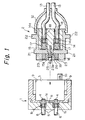
- FIGS. 1 through 4 show a general construction of an embodiment of a connector.
- a stationary side connector housing 1 provided on a car body of the electric automobile is shown on the left side in the drawings and an insertion side connector housing 2 provided on a distal end of a cable connected to a charger and adapted to be detachably connected to the stationary side connector housing 1 is shown on the right side.
- the stationary side connector housing 1 As shown also in FIG. 8, the stationary side connector housing 1 is generally formed into a rectangular block and is provided with a cylindrical recess 3 having an opening at a front end face (a right end face in FIG. 1).
- the stationary side connector housing 1 is provided on a bottom wall la of the recess 3 (a left wall in FIG. 1) with a pair of juxtaposed stationary side electrodes 4 and 4.
- the stationary side electrodes 4, 4 are movably accommodated in recesses lb, lb in the bottom wall la and constrained from moving to a maximum projecting position to the right direction by an enlarged diameter portion at a proximal end.
- stationary side electrodes 4, 4 are biased to the right side in the drawings by springs 5, 5 in recesses lb, lb to project in the recess 3 normally. Cables 6, 6 connected to the stationary side electrodes 4, 4 respectively are introduced outwardly (left side) from the stationary side connector housing 1.
- three stationary side signal terminals 7 are provided on a bottom wall la. An end of each leading line 8 is connected to each stationary side signal terminals 7 while the end of the line 8 is drawn out of the connector housing 1.
- the stationary side signal terminal 7 serves to electrically detect whether the insertion side connector housing 2 is connected to the stationary side connector housing 1. The signal terminals 7 contact with insertion side signal terminals provided on the insertion side connector housing 2 respectively upon coupling of the housing 2.
- the stationary side connector housing 1 is provided on the bottom wall la with a hole lc to receive a lock pin 25 on the insertion side connector housing 2 mentioned hereinafter.
- a pair of guide grooves 9, 9 are formed in the inner face of the cavity 3 and arranged symmetrically. As shown in FIG. 9, the guide grooves 9, 9 are formed on the right and left sides at the open end of the cavity 3 and defined by a straight face 9a extending from the open end to an inner part of the cavity, a rotary guide face 9b extending from a proximal end of the straight face 9a to a peripheral position (in a clockwise direction taken from the open end), and a shoulder 9c extending from the rotary guide face 9b to an inner part of the cavity 3 and further extending to a peripheral position.
- the stationary side connector housing 1 is provided on a front end face (the open end of the cavity 3) diagonally with a pair of engaging projections 10, as shown in FIG. 8.
- the engaging projections 10 together with lock pieces on the insertion side connector housing 2 mentioned hereinafter constitute a locking mechanism.
- the engaging projections 10 receive the lock pieces to lock them when the lock pieces rotate in the clockwise direction.
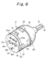
- the insertion side connector housing 2 is constructed in association with the stationary side connector housing 1 mentioned above. As shown in FIGS. 6 and 7, the insertion side connector housing 2 is formed into a cylindrical shape suitable for being received in the cavity 3. A cover 12 is mounted on a proximal end (right end) of the housing 2 while a cable 13 is drawn out of the cover 12 (to a right side).
- the insertion side connector housing 2 as shown in FIG. 7, is provided with a both block 14, a movable plate or movable member 15, and a stationary plate 16.
- the body block 14 is formed into a cylindrical shape having a size smaller than that of the housing 2 and provided on an end face with a pair of accommodating recesses 14a, 14a arranged on a diametrical direction.
- the insertion electrodes 17, 17 and springs 18, 18 are accommodated in the recesses 14a, 14a, respectively.
- the insertion electrodes 17, 17 are biased outwardly from the end face of the body block 14 by the springs 18, 18.
- the insertion side electrode 17 is provided on a distal end with a round portion.
- the cable 13 is connected to the insertion side electrode 17.
- the body block 14 is provided on a center of the top end with a hub portion 19 having a screwed bore.
- the movable member 15 is open at a proximal end face (right end face).
- the movable member 15 is formed into a cylindrical shape for receiving the body block 14 in the interior.
- the movable member 15 is provided on the top wall (left end portion) with a pair of through-holes 15a, 15a in opposition to the accommodating recesses 14a, 14a (insertion side electrodes 17, 17).
- Movable electrodes 20, 20 are accommodated in the through-holes 15a, 15a.
- the movable electrode 20 is provided on a distal end face with a round projection and on a proximal end face with a round recess.
- the movable member 15 is provided on a center of the distal end wall with an aperture 15b through which the hub portion 19 passes.
- the movable member 15 is also provided diametrically on the distal end on the outer periphery with a pair of ribs 21, 21, as shown in FIGS. 6 and 7 and diametrically on the proximal end on the outer periphery with a pair of lock pieces 22, 22.
- diametrical lines arranging the ribs 21 and lock pieces 22 are greatly inclined with respect to a diametrical line arranging the through-holes 15a, 15a (movable electrodes 20, 20).
- the stationary plate 16 is formed into a disc shape corresponding to the distal end face of the movable member 15 and provided with a pair of apertures 16a, 16a corresponding to the recesses 14a, 14a in the body block 14. Intermediate electrodes 23, 23 are accommodated in the apertures 16a, 16a.
- the stationary plate 16 is provided at a center with a bolt hole 16b.
- the stationary plate 16 is provided on an upper portion with an insertion side signal terminal 24 disposed laterally. As shown in FIG. 5, the insertion side signal terminal 24 has three bosses 24a extending outwardly. Further, the stationary plate 16 is provided on a lower portion with a lock pin 25 extending outwardly as shown in FIGS. 4 and 7.
- the insertion side connector housing 2 is constructed by mounting the movable member 15 onto the body block 14 from the left side, mounting the stationary plate 16 on the top end face of the movable member 15, inserting a bolt 26 (see FIGS. 1 to 4) into the bolt hole 16b in the stationary plate 16, and fastening the bolt 26 into the hub portion 19 of the body block 14.
- the stationary plate 16 is secured to the body block 14 while the movable member 15 rotatably mounts on the outer periphery of the body block 14.
- the insulation side electrodes 17, movable electrodes 20, and intermediate electrodes 23 are aligned to conduct them as shown in FIG. 3.
- the movable electrodes 20 are turned to another position on the body block 14, the movable electrodes 20 are displaced from the confronting position of the insertion side electrodes 17 and intermediate electrodes 23 to electrically disconnect them.
- the cover 12 mounts on an outer periphery of the proximal end of the movable member 15.
- the insertion side connector housing 2 Upon coupling the connector, the insertion side connector housing 2 is inserted into the cavity 3 in the stationary side connector housing 1 so that the ribs 21 of the movable member 15 into the straight face 9a of the guide grooves 9.
- the intermediate electrodes 23 in the stationary plate 16 are arranged horizontally as shown in FIG. 1
- the insertion side signal terminal 24 is arranged in an upper position as shown in FIG. 4
- the lock pin 25 is arranged in a lower position and the ribs 21 and lock pieces 22 of the movable member 15 are disposed in a horizontal position shown by two-dot chain lines in FIG. 6.
- the movable member 15 is turned in the clockwise direction so that the ribs 21 are guided in the rotary guide face 9b of the guide groove 9.
- the movable electrodes 20 are displaced a little from the insertion side electrodes 17 and intermediate electrodes 23 as shown in FIG. 10B and the insertion side signal terminal 24 is spaced away from the stationary side signal terminal 7 since the insertion side connector housing 2 (stationary plate 16) does not contact with the bottom wall la of the cavity 3.
- the lock pieces 22 are still spaced apart slightly from the top end face of the stationary side connector housing 1 and spaced away circumferentially slightly from the engaging projections 10.
- the movable member 15 is further turned in the clockwise direction from that position after pushing and inserting slightly the movable member 15 so that the ribs 21 are guided by the shoulder 9c of the guide groove 9.
- the lock pieces 22 abut on the top end face of the stationary side connector housing 1 and slide on the face to fit in the engaging projections 10. Consequently, the locking mechanism is brought into the coupling position to maintain the connector housings 1 and 2 in the coupling position.
- the insertion side connector housing 2 abuts on the bottom wall 1a, each boss 24a of the insertion side signal terminal 24 contact with each stationary side signal terminal 7, and the lock pin 25 completely fitting in the hole 1c.
- the movable electrodes 20 rotates to a position between the insertion side electrodes 17 and the intermediate electrodes 23 to conduct them, and the intermediate electrodes 23 push the stationary side electrodes 4 against the spring 5, thereby bringing the electrodes 17 and 4 into a conductive state.
- the battery is electrically connected to the charger to be charged.
- This charging can be carried out under a condition in which the stationary side signal terminals are brought into a conductive state through the insertion side signal terminal 24. Since, under the action of the spring 5, the stationary side electrodes 4 push the insertion side connector housing 2 toward the insertion side, the lock pieces 22 are engaged with the engaging projections 10 to maintain a locked position. When the lock pieces 22 are disengaged from the projections 10, that is, the locking mechanism is in a detaching position, the stationary side electrodes 4 under the action of the spring 5 push the insertion side connector housing 2 toward the insertion side, so that the insertion side signal terminal 24 is disconnected from the stationary side signal terminals 7.
- the movable member 15 is turned in an anti-clockwise direction to draw the lock pieces 22 out of the engaging projections 10. Then, the locking mechanism is in the detaching position.
- the spring 5 pushes back the insertion side connector housing 2 so that the housing 2 is spaced away slightly from the bottom wall la. Consequently, the insertion side signal terminal 24 is spaced away from the stationary side signal terminals 7 and the electrodes 4 and 17 are brought into a non-conductive state.
- the connector housing 2 can be detached from the connector housing 1 by drawing the movable member 15 on the body block 14 toward the insertion side.
- both electrodes 4 and 17 only when both connector housing 1 and 2 are locked in the coupling position, are the electrodes 4 and 17 brought into a conductive state.
- the electrodes 4 and 17 remain in a non-conductive state. Accordingly, in comparison with the conventional connector in which both electrodes are brought into a conductive state even if both connector housings are in an incomplete coupling position, both electrodes 4 and 17 in the connector of the present invention are positively brought into a conductive state in the coupling position of both connector housings 1 and 2 and both electrodes 4 and 17 are inhibited from conducting in the incomplete coupling position in which both connector housings 1 and 2 are easily detached from each other. Even if both connector housings 1 and 2 happen to be changed from an incomplete coupling position to a detaching position, it is possible to prevent the occurrence of an electrical failure such as an arc.
Landscapes
- Engineering & Computer Science (AREA)
- Power Engineering (AREA)
- Transportation (AREA)
- Mechanical Engineering (AREA)
- Details Of Connecting Devices For Male And Female Coupling (AREA)
- Connector Housings Or Holding Contact Members (AREA)
Applications Claiming Priority (2)
| Application Number | Priority Date | Filing Date | Title |
|---|---|---|---|
| JP5106200A JP2842145B2 (ja) | 1993-04-07 | 1993-04-07 | コネクタ |
| JP106200/93 | 1993-04-07 |
Publications (3)
| Publication Number | Publication Date |
|---|---|
| EP0626737A2 true EP0626737A2 (fr) | 1994-11-30 |
| EP0626737A3 EP0626737A3 (fr) | 1996-01-03 |
| EP0626737B1 EP0626737B1 (fr) | 1998-12-09 |
Family
ID=14427529
Family Applications (1)
| Application Number | Title | Priority Date | Filing Date |
|---|---|---|---|
| EP94302405A Expired - Lifetime EP0626737B1 (fr) | 1993-04-07 | 1994-04-05 | Connecteur électrique |
Country Status (4)
| Country | Link |
|---|---|
| US (1) | US5431580A (fr) |
| EP (1) | EP0626737B1 (fr) |
| JP (1) | JP2842145B2 (fr) |
| DE (1) | DE69415079T2 (fr) |
Cited By (6)
| Publication number | Priority date | Publication date | Assignee | Title |
|---|---|---|---|---|
| EP0949723A1 (fr) * | 1998-04-09 | 1999-10-13 | Societe Anonyme Dite: Carrier Kheops Bac | Connecteur électrique hermaphrodite de sécurité |
| WO2010060679A1 (fr) * | 2008-11-03 | 2010-06-03 | Robert Bosch Gmbh | Dispositif d'enfichage électrique |
| WO2012072737A1 (fr) * | 2010-12-03 | 2012-06-07 | Rema Lipprandt Gmbh & Co. Kg | Partie de prise mâle côté câble de chargement d'une prise de courant électrique d'un véhicule |
| EP2555340A1 (fr) * | 2011-08-03 | 2013-02-06 | Renault S.A.S. | Fiche de raccordement électrique modulable, élément électrique pour une telle fiche, set d'éléments électriques et véhicule électrique comportant une telle fiche |
| EP2720324A1 (fr) * | 2012-10-10 | 2014-04-16 | Dai-Ichi Seiko Co., Ltd. | Connecteur électrique |
| CN107645086A (zh) * | 2017-04-07 | 2018-01-30 | 孝感市卡普隆日用品有限公司 | 一种改进型环保除尘装置 |
Families Citing this family (39)
| Publication number | Priority date | Publication date | Assignee | Title |
|---|---|---|---|---|
| US6305963B1 (en) * | 1996-08-16 | 2001-10-23 | Agilent Technologies, Inc. | Push-lock BNC connector |
| US5733152A (en) * | 1996-10-09 | 1998-03-31 | Royal Die & Stamping Co., Inc. | Battery terminal adaptor and connector |
| US6517359B1 (en) | 1999-05-21 | 2003-02-11 | Agilent Technologies, Inc. | System and method for mating electrical connections |
| US6524123B2 (en) * | 2001-01-19 | 2003-02-25 | Agilent Technologies, Inc. | Self-aligning, quick-release connector |
| JP2003017198A (ja) * | 2001-07-02 | 2003-01-17 | Honda Motor Co Ltd | サービスプラグ |
| US6666701B1 (en) * | 2002-07-22 | 2003-12-23 | Signet Scientific Company | Bayonet-type electrical connector assembly |
| US6855008B1 (en) | 2003-10-06 | 2005-02-15 | Royal Die & Stamping Co., Inc. | Fuse holder with adjustable terminals |
| US6932650B1 (en) | 2004-03-25 | 2005-08-23 | Royal Die & Stamping Co., Inc. | Fused battery terminal connector |
| US20060003627A1 (en) * | 2004-07-01 | 2006-01-05 | Erik Freitag | Fused battery terminal connector |
| US7980865B2 (en) * | 2005-12-22 | 2011-07-19 | Intel Corporation | Substrate with raised edge pads |
| DE102008017915B4 (de) * | 2008-04-08 | 2010-03-04 | Wago Verwaltungsgesellschaft Mbh | Set aus Anschlussadapter und Anschlussklemme sowie Anschlussadapter und Anschlusselement hierzu |
| US7988479B2 (en) * | 2009-04-22 | 2011-08-02 | Christopher Michael Hankins | Bayonet connector |
| US8550843B2 (en) | 2010-11-22 | 2013-10-08 | Andrew Llc | Tabbed connector interface |
| US8876549B2 (en) | 2010-11-22 | 2014-11-04 | Andrew Llc | Capacitively coupled flat conductor connector |
| JP2012228741A (ja) * | 2011-04-25 | 2012-11-22 | Makita Corp | 電動工具 |
| US8608507B2 (en) | 2011-10-20 | 2013-12-17 | Andrew Llc | Tool-less and visual feedback cable connector interface |
| JP6031006B2 (ja) * | 2013-07-02 | 2016-11-24 | 矢崎総業株式会社 | 端子金具の接続構造及び回転嵌合式コネクタ |
| WO2015024239A1 (fr) * | 2013-08-22 | 2015-02-26 | 吉瑞高新科技股份有限公司 | Cigarette électronique |
| CN103904486A (zh) * | 2014-03-18 | 2014-07-02 | 东莞讯滔电子有限公司 | 插座连接器及电连接器组合 |
| TWI583072B (zh) * | 2014-07-17 | 2017-05-11 | 緯創資通股份有限公司 | 定位結構及連接器組件 |
| US9651420B2 (en) | 2014-10-13 | 2017-05-16 | Te Connectivity Corporation | Light sensor assembly |
| US10398169B2 (en) | 2015-06-25 | 2019-09-03 | Altria Client Services Llc | E-vapor device including at least one of a bayonet connector and a connector with a knurled pattern for forming a welded junction |
| CN106379448B (zh) * | 2016-10-20 | 2019-03-15 | 佛山市顺德区天轴车料有限公司 | 一种公共电动自行车 |
| CN107097671B (zh) * | 2017-05-04 | 2018-08-28 | 浙江黄岩天盛汽车零部件有限公司 | 一种便捷式的新能源汽车充电装置 |
| US10008789B1 (en) | 2017-07-10 | 2018-06-26 | Royal Die & Stamping, Llc | Angled bolt T-bar battery terminal clamp |
| CN107399246B (zh) * | 2017-08-08 | 2018-10-16 | 浦江县飞通电子科技有限公司 | 一种新能源汽车充电装置 |
| CN107404053A (zh) * | 2017-09-01 | 2017-11-28 | 周军美 | 一种桥梁建筑设备 |
| CN107332054A (zh) * | 2017-09-01 | 2017-11-07 | 周军美 | 一种新型桥梁建筑设备 |
| CN107458261B (zh) * | 2017-09-18 | 2018-11-09 | 新昌县奇立环保科技有限公司 | 一种新能源汽车充电设备 |
| US11196206B2 (en) * | 2018-07-19 | 2021-12-07 | Hirel Connectors, Inc. | Electrical connector with field serviceable shell assembly |
| CN109038073B (zh) * | 2018-08-10 | 2020-05-19 | 徐纯纯 | 用于计算机网络连接的连接固定装置 |
| JP7013398B2 (ja) * | 2019-01-15 | 2022-01-31 | 本田技研工業株式会社 | コネクタ装置及びコネクタ接続判定装置 |
| CN111137153A (zh) * | 2019-03-26 | 2020-05-12 | 青岛特来电新能源科技有限公司 | 充电系统以及电动车 |
| US10950992B1 (en) * | 2019-08-29 | 2021-03-16 | Peter Brewster | Electrical fixture mounting system |
| SE544579C2 (en) * | 2019-12-06 | 2022-07-26 | Nuculus AS | Safety electrical outlet |
| CN112333886B (zh) * | 2020-10-14 | 2023-01-03 | 浙江工商职业技术学院 | 一种供电设备 |
| US20220259902A1 (en) * | 2021-02-16 | 2022-08-18 | Lear Corporation | Modular attachment mechanism and method |
| JP2024086115A (ja) * | 2022-12-16 | 2024-06-27 | 株式会社オートネットワーク技術研究所 | コネクタ装置およびワイヤハーネス |
| CN120657469A (zh) * | 2024-03-15 | 2025-09-16 | 台达电子工业股份有限公司 | 安全连接结构及安全连接器 |
Family Cites Families (9)
| Publication number | Priority date | Publication date | Assignee | Title |
|---|---|---|---|---|
| US3124404A (en) * | 1964-03-10 | Electrical male connector | ||
| US1742850A (en) * | 1928-05-05 | 1930-01-07 | Harry A Douglas | Circuit-continuing device |
| US1862097A (en) * | 1929-09-18 | 1932-06-07 | Ford Motor Co | Connecting plug |
| FR795132A (fr) * | 1934-09-21 | 1936-03-04 | Stotz Kontakt Gmbh | Prise de courant formant interrupteur, antigrisouteuse |
| US3701965A (en) * | 1971-07-28 | 1972-10-31 | Essex International Inc | Connector for electrical terminals |
| US4429938A (en) * | 1982-01-06 | 1984-02-07 | Midland-Ross Corporation | Locking device for interfitting members |
| JPH04124774A (ja) * | 1990-09-14 | 1992-04-24 | N T T Data Tsushin Kk | 関係データベースにおける階層構造のデータ蓄積方法 |
| DE4030154A1 (de) * | 1990-09-24 | 1991-05-16 | Gerhard Neumann | Steckvorrichtung |
| JP3151235B2 (ja) * | 1991-05-08 | 2001-04-03 | 本田技研工業株式会社 | 電気自動車等の充電用コネクタ |
-
1993
- 1993-04-07 JP JP5106200A patent/JP2842145B2/ja not_active Expired - Fee Related
-
1994
- 1994-03-30 US US08/219,502 patent/US5431580A/en not_active Expired - Fee Related
- 1994-04-05 EP EP94302405A patent/EP0626737B1/fr not_active Expired - Lifetime
- 1994-04-05 DE DE69415079T patent/DE69415079T2/de not_active Expired - Fee Related
Cited By (10)
| Publication number | Priority date | Publication date | Assignee | Title |
|---|---|---|---|---|
| EP0949723A1 (fr) * | 1998-04-09 | 1999-10-13 | Societe Anonyme Dite: Carrier Kheops Bac | Connecteur électrique hermaphrodite de sécurité |
| FR2777391A1 (fr) * | 1998-04-09 | 1999-10-15 | Carrier Kheops Bac | Connecteur electrique hermaphrodite de securite |
| WO2010060679A1 (fr) * | 2008-11-03 | 2010-06-03 | Robert Bosch Gmbh | Dispositif d'enfichage électrique |
| US8647133B2 (en) | 2008-11-03 | 2014-02-11 | Robert Bosch Gmbh | Electrical plug connection |
| WO2012072737A1 (fr) * | 2010-12-03 | 2012-06-07 | Rema Lipprandt Gmbh & Co. Kg | Partie de prise mâle côté câble de chargement d'une prise de courant électrique d'un véhicule |
| EP2555340A1 (fr) * | 2011-08-03 | 2013-02-06 | Renault S.A.S. | Fiche de raccordement électrique modulable, élément électrique pour une telle fiche, set d'éléments électriques et véhicule électrique comportant une telle fiche |
| EP2720324A1 (fr) * | 2012-10-10 | 2014-04-16 | Dai-Ichi Seiko Co., Ltd. | Connecteur électrique |
| US9437972B2 (en) | 2012-10-10 | 2016-09-06 | Dai-Ichi Seiko Co., Ltd. | Electric connector |
| US9461405B2 (en) | 2012-10-10 | 2016-10-04 | Dai-Ichi Seiko Co., Ltd. | Electric connector |
| CN107645086A (zh) * | 2017-04-07 | 2018-01-30 | 孝感市卡普隆日用品有限公司 | 一种改进型环保除尘装置 |
Also Published As
| Publication number | Publication date |
|---|---|
| EP0626737A3 (fr) | 1996-01-03 |
| DE69415079T2 (de) | 1999-04-29 |
| JPH06295760A (ja) | 1994-10-21 |
| EP0626737B1 (fr) | 1998-12-09 |
| US5431580A (en) | 1995-07-11 |
| JP2842145B2 (ja) | 1998-12-24 |
| DE69415079D1 (de) | 1999-01-21 |
Similar Documents
| Publication | Publication Date | Title |
|---|---|---|
| EP0626737B1 (fr) | Connecteur électrique | |
| EP0624925B1 (fr) | Connecteur électrique avec fonction de détection d'enfichage | |
| EP0622870B1 (fr) | Connecteur électrique à ressort précontraint | |
| EP0644622B1 (fr) | Assemblage de connecteur pour charger un véhicule électrique | |
| US5639256A (en) | Feeder connector | |
| US6225153B1 (en) | Universal charge port connector for electric vehicles | |
| US6371768B1 (en) | Universal charge port connector for electric vehicles | |
| US6203355B1 (en) | Universal charge port connector for electric vehicles | |
| EP0622869B1 (fr) | Dispositif de connecteur | |
| JP2752032B2 (ja) | 給電コネクタ | |
| US4335931A (en) | Power cable connector with retention spring | |
| US5672073A (en) | Connector having engagement detecting device | |
| EP3118941B1 (fr) | Connecteur électrique et gabarit de retour | |
| EP0418790B1 (fr) | Mécanisme confirmant le parfait couplage d'un connecteur électrique | |
| US5618201A (en) | Connector having engagement detecting device | |
| US5391087A (en) | Connector | |
| US4978311A (en) | Electrical connector having connector-operable shorting bar | |
| US20030057958A1 (en) | Lever fitting-type manual disconnector | |
| CA2278910C (fr) | Connecteur d'alimentation a poignee de manoeuvre | |
| KR102749301B1 (ko) | 커넥터 장치 | |
| KR20180126873A (ko) | 충전 커넥터 잠금장치 | |
| CN109787039B (zh) | 扳手式锁止紧固装置 | |
| JP3272248B2 (ja) | サービスプラグのレバー保持機構 | |
| US6572401B2 (en) | Connector locking member with disengagement feature | |
| CN219659006U (zh) | 一种轻巧型大电流连接器 |
Legal Events
| Date | Code | Title | Description |
|---|---|---|---|
| PUAI | Public reference made under article 153(3) epc to a published international application that has entered the european phase |
Free format text: ORIGINAL CODE: 0009012 |
|
| 17P | Request for examination filed |
Effective date: 19940420 |
|
| AK | Designated contracting states |
Kind code of ref document: A2 Designated state(s): DE GB |
|
| PUAL | Search report despatched |
Free format text: ORIGINAL CODE: 0009013 |
|
| AK | Designated contracting states |
Kind code of ref document: A3 Designated state(s): DE GB |
|
| 17Q | First examination report despatched |
Effective date: 19970214 |
|
| GRAG | Despatch of communication of intention to grant |
Free format text: ORIGINAL CODE: EPIDOS AGRA |
|
| GRAG | Despatch of communication of intention to grant |
Free format text: ORIGINAL CODE: EPIDOS AGRA |
|
| GRAH | Despatch of communication of intention to grant a patent |
Free format text: ORIGINAL CODE: EPIDOS IGRA |
|
| GRAH | Despatch of communication of intention to grant a patent |
Free format text: ORIGINAL CODE: EPIDOS IGRA |
|
| GRAA | (expected) grant |
Free format text: ORIGINAL CODE: 0009210 |
|
| AK | Designated contracting states |
Kind code of ref document: B1 Designated state(s): DE GB |
|
| REF | Corresponds to: |
Ref document number: 69415079 Country of ref document: DE Date of ref document: 19990121 |
|
| PLBE | No opposition filed within time limit |
Free format text: ORIGINAL CODE: 0009261 |
|
| STAA | Information on the status of an ep patent application or granted ep patent |
Free format text: STATUS: NO OPPOSITION FILED WITHIN TIME LIMIT |
|
| 26N | No opposition filed | ||
| REG | Reference to a national code |
Ref country code: GB Ref legal event code: IF02 |
|
| PGFP | Annual fee paid to national office [announced via postgrant information from national office to epo] |
Ref country code: GB Payment date: 20020404 Year of fee payment: 9 |
|
| PGFP | Annual fee paid to national office [announced via postgrant information from national office to epo] |
Ref country code: DE Payment date: 20020410 Year of fee payment: 9 |
|
| PG25 | Lapsed in a contracting state [announced via postgrant information from national office to epo] |
Ref country code: GB Free format text: LAPSE BECAUSE OF NON-PAYMENT OF DUE FEES Effective date: 20030405 |
|
| PG25 | Lapsed in a contracting state [announced via postgrant information from national office to epo] |
Ref country code: DE Free format text: LAPSE BECAUSE OF NON-PAYMENT OF DUE FEES Effective date: 20031101 |
|
| GBPC | Gb: european patent ceased through non-payment of renewal fee |
Effective date: 20030405 |