EP0626772A2 - Schaltung zur Frequenzsprungmodulation - Google Patents
Schaltung zur Frequenzsprungmodulation Download PDFInfo
- Publication number
- EP0626772A2 EP0626772A2 EP94201210A EP94201210A EP0626772A2 EP 0626772 A2 EP0626772 A2 EP 0626772A2 EP 94201210 A EP94201210 A EP 94201210A EP 94201210 A EP94201210 A EP 94201210A EP 0626772 A2 EP0626772 A2 EP 0626772A2
- Authority
- EP
- European Patent Office
- Prior art keywords
- frequency
- saw
- modulating circuit
- circuit according
- inductor
- Prior art date
- Legal status (The legal status is an assumption and is not a legal conclusion. Google has not performed a legal analysis and makes no representation as to the accuracy of the status listed.)
- Withdrawn
Links
Images
Classifications
-
- B—PERFORMING OPERATIONS; TRANSPORTING
- B60—VEHICLES IN GENERAL
- B60R—VEHICLES, VEHICLE FITTINGS, OR VEHICLE PARTS, NOT OTHERWISE PROVIDED FOR
- B60R25/00—Fittings or systems for preventing or indicating unauthorised use or theft of vehicles
- B60R25/20—Means to switch the anti-theft system on or off
- B60R25/24—Means to switch the anti-theft system on or off using electronic identifiers containing a code not memorised by the user
-
- G—PHYSICS
- G07—CHECKING-DEVICES
- G07C—TIME OR ATTENDANCE REGISTERS; REGISTERING OR INDICATING THE WORKING OF MACHINES; GENERATING RANDOM NUMBERS; VOTING OR LOTTERY APPARATUS; ARRANGEMENTS, SYSTEMS OR APPARATUS FOR CHECKING NOT PROVIDED FOR ELSEWHERE
- G07C9/00—Individual registration on entry or exit
- G07C9/00174—Electronically operated locks; Circuits therefor; Nonmechanical keys therefor, e.g. passive or active electrical keys or other data carriers without mechanical keys
- G07C9/00182—Electronically operated locks; Circuits therefor; Nonmechanical keys therefor, e.g. passive or active electrical keys or other data carriers without mechanical keys operated with unidirectional data transmission between data carrier and locks
-
- H—ELECTRICITY
- H04—ELECTRIC COMMUNICATION TECHNIQUE
- H04L—TRANSMISSION OF DIGITAL INFORMATION, e.g. TELEGRAPHIC COMMUNICATION
- H04L27/00—Modulated-carrier systems
- H04L27/10—Frequency-modulated carrier systems, i.e. using frequency-shift keying
- H04L27/12—Modulator circuits; Transmitter circuits
-
- G—PHYSICS
- G07—CHECKING-DEVICES
- G07C—TIME OR ATTENDANCE REGISTERS; REGISTERING OR INDICATING THE WORKING OF MACHINES; GENERATING RANDOM NUMBERS; VOTING OR LOTTERY APPARATUS; ARRANGEMENTS, SYSTEMS OR APPARATUS FOR CHECKING NOT PROVIDED FOR ELSEWHERE
- G07C9/00—Individual registration on entry or exit
- G07C9/00174—Electronically operated locks; Circuits therefor; Nonmechanical keys therefor, e.g. passive or active electrical keys or other data carriers without mechanical keys
- G07C2009/00753—Electronically operated locks; Circuits therefor; Nonmechanical keys therefor, e.g. passive or active electrical keys or other data carriers without mechanical keys operated by active electrical keys
- G07C2009/00769—Electronically operated locks; Circuits therefor; Nonmechanical keys therefor, e.g. passive or active electrical keys or other data carriers without mechanical keys operated by active electrical keys with data transmission performed by wireless means
- G07C2009/00793—Electronically operated locks; Circuits therefor; Nonmechanical keys therefor, e.g. passive or active electrical keys or other data carriers without mechanical keys operated by active electrical keys with data transmission performed by wireless means by Hertzian waves
-
- G—PHYSICS
- G07—CHECKING-DEVICES
- G07C—TIME OR ATTENDANCE REGISTERS; REGISTERING OR INDICATING THE WORKING OF MACHINES; GENERATING RANDOM NUMBERS; VOTING OR LOTTERY APPARATUS; ARRANGEMENTS, SYSTEMS OR APPARATUS FOR CHECKING NOT PROVIDED FOR ELSEWHERE
- G07C2209/00—Indexing scheme relating to groups G07C9/00 - G07C9/38
- G07C2209/60—Indexing scheme relating to groups G07C9/00174 - G07C9/00944
- G07C2209/61—Signal comprising different frequencies, e.g. frequency hopping
Definitions
- This invention relates to a frequency shift keying modulating unit for use, for example, in a low power transmitter used in a remote keyless entry, alarm or similar system for a motor vehicle.
- a remote system for a motor vehicle has a base unit in a vehicle and a remote unit carried by the driver.
- the remote unit is typically of low power so as to be battery operated and quite small, designed about the size of a keyring fob.
- Such remote units are generally configured to transmit at least a stream of binary data utilising known radio frequency transmission modulation techniques.
- the most common technique utilised in this application is Amplitude Shift Keying (ASK).
- ASK Amplitude Shift Keying
- FSK Frequency Shift Keying
- the present invention seeks to provide an improved FSK modulating circuit.
- an FSK modulating circuit as specified in claim 1.
- a transmitter having improved noise immunity characteristics relative to ASK systems currently utilised in the art, and such a transmitter in a low cost and highly reliable manner using only a minimal number of components and minimal power so as to be applicable to a battery operated unit. It is also possible in some embodiments to provide a wide deviation in frequency between a first and second transmission frequency corresponding to binary data transmission in a FSK modulating transmitter.
- a preferred embodiment provides a low-power requirement FSK modulating circuit which has an oscillator amplifier tuned for RF oscillation and responsive to an oscillatory input thereto.
- a Surface Acoustic Wave (SAW) transducer having a natural resonant frequency in a stand alone oscillatory configuration provides a first frequency for the FSK modulating circuit.
- a single reactive component located between the SAW transducer and the RF oscillator amplifier provides a pulling effect upon the SAW natural resonant frequency so as to change the oscillatory frequency input to the RF oscillator amplifier to a second frequency.
- a PIN switching diode in parallel with the reactive component provides a bypass of that reactive component such that the SAW transducer can provide its natural resonant frequency as an input to the RF oscillator amplifier. Means for forward and reverse biasing the PIN diode can provide selective control over these two independent frequencies.
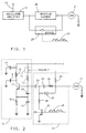
- an RF oscillator amplifier 10 has an antenna 15 which has an operating oscillating frequency equal to that of RF oscillator amplifier 10.
- SAW transducer 21 is coupled to ground at one terminal thereof and has its output terminal coupled to one end of the parallel combination of reactive element 26 and bypass 27, illustrated as a switch. The other end of the parallel combination 26, 27 is coupled to the input of RF oscillator amplifier 10.
- Data stream 23 represents logic states controlling the state of bypass 27, in this example closing or opening the switch.
- the circuit of Figure 1 includes the alternate arrangement of a reactive path to ground from RF oscillator amplifier 10 through a) the combination of reactive element 26 and SAW transducer 21 or b) directly through SAW transducer 21 via bypass 27, circumventing reactive element 26.
- the resultant output on antennae 15 has two distinct and independent frequencies, one for each logic state of data stream 23.
- FIG 2 illustrates a preferred circuit for the modulator of Figure 1.
- Power (+V) and ground correspond to a low voltage DC power source.
- a single 3 volt watch battery or similar disc-like disposable battery is sufficient and preferred.
- RF oscillator amplifier 10 is preferably a Colpitts type oscillator, which has a broad oscillation range and therefore is able to match readily with SAW transducers which have natural oscillatory frequencies which tend to vary more widely than other oscillator elements. Colpitts oscillators are also relatively inexpensive due to use of capacitive elements as opposed to inductive elements in the oscillatory loop.
- RF oscillator amplifier 10 utilises a single transistor 17 to perform the multiple tasks of stable oscillatory switching and amplification sufficient to drive antenna 15 to a readily detectable output level.
- Antenna 15 is preferably a trace of metal patterned on a circuit board to provide a degree of inductance. In this embodiment, the inductance of antenna 15 is nominally 75nH.
- Antenna 15 is coupled at one end thereof to both the power terminal of the power supply and a first terminal of decoupling capacitor 14, and at the other end thereof to the collector of transistor 17.
- a second terminal of decoupling capacitor 14 is coupled to ground.
- Decoupling capacitor 14, nominally 270pF decouples the generated RF signals from the power terminal of the battery during RF generation.
- Resistor 12 nominally 20 k ⁇ , is coupled in series with normally open switch 11 between the power terminal (V+) of the battery and the base of transistor 17 to provide bias for oscillator operation.
- Normally open switch 11 is closed when transmitting since at other times oscillation bias is not desirable and would unnecessarily reduce battery life.
- Other functionally equivalent means of providing bias voltage to the base of transistor 17 may include supplying a high logic level signal thereto when transmitting is initiated.
- Voltage dividing capacitors 13 and 19 are nominally 5.6 pF and 3.9pF respectively and capacitor 16 (used to control gain and amplitude peaking) is nominally between 1 and 5 pF.
- Antenna 15, capacitor 16, transistor 17, voltage divider configured capacitors 13, 19 form the oscillatory elements of RF oscillator amplifier 10 and, as specified, will support oscillation broadly centred around 300 MHz.
- a remaining low impedance signal path back from the base of transistor 17 to ground is provided and controlled externally of RF oscillator amplifier 10 by block 20 so as to establish the precise oscillation frequency.
- Block 20 includes a pair of selectable low impedance signal paths from the base of transistor 17 to ground.
- a high logic level from data stream 23 on data line 40 causes transistor switch 29 to turn on, resulting in a forward biased PIN diode 27 through bias resistors 22 and 28.
- PIN diode 27 With PIN diode 27 conducting, inductor 26 is bypassed and the effective low impedance signal path is through SAW transducer 21.
- SAW transducer 21 has a natural stand-alone resonant frequency of nominally 300MHz, consistent with the Colpitts oscillator central frequency.
- Capacitor 24 is nominally 27 pF and provides for DC blocking but has no consequential effect upon the oscillatory loop.
- a low logic level on data line 23 causes transistor switch 29 to turnoff resulting in a non-conducting PIN diode 27.
- PIN diode 27 With PIN diode 27 not conducting, inductor 26 in combination with SAW transducer is the effective low impedance signal path.
- Capacitor 25 is nominally 27 pF and just like capacitor 24 provides for DC blocking with no consequential effect upon the oscillatory loop.
Landscapes
- Engineering & Computer Science (AREA)
- Computer Networks & Wireless Communication (AREA)
- Mechanical Engineering (AREA)
- Physics & Mathematics (AREA)
- General Physics & Mathematics (AREA)
- Signal Processing (AREA)
- Oscillators With Electromechanical Resonators (AREA)
- Transmitters (AREA)
Applications Claiming Priority (2)
| Application Number | Priority Date | Filing Date | Title |
|---|---|---|---|
| US08/065,336 US5367537A (en) | 1993-05-24 | 1993-05-24 | Saw-based FSK modulating circuit |
| US65336 | 2002-10-04 |
Publications (2)
| Publication Number | Publication Date |
|---|---|
| EP0626772A2 true EP0626772A2 (de) | 1994-11-30 |
| EP0626772A3 EP0626772A3 (de) | 1994-12-21 |
Family
ID=22062005
Family Applications (1)
| Application Number | Title | Priority Date | Filing Date |
|---|---|---|---|
| EP94201210A Withdrawn EP0626772A3 (de) | 1993-05-24 | 1994-05-02 | Schaltung zur Frequenzsprungmodulation |
Country Status (2)
| Country | Link |
|---|---|
| US (1) | US5367537A (de) |
| EP (1) | EP0626772A3 (de) |
Cited By (3)
| Publication number | Priority date | Publication date | Assignee | Title |
|---|---|---|---|---|
| FR2740635A1 (fr) * | 1995-10-26 | 1997-04-30 | Siemens Ag | Emetteur de code, notamment pour un systeme antivol d'un vehicule automobile |
| EP0847170A1 (de) * | 1996-12-05 | 1998-06-10 | UNITED TECHNOLOGIES AUTOMOTIVE, Inc. | Oszillator für Frequenzsprungmodulation |
| US6225873B1 (en) | 1995-12-01 | 2001-05-01 | Lear Automotive Dearborn, Inc. | Frequency shift key modulating oscillator |
Families Citing this family (11)
| Publication number | Priority date | Publication date | Assignee | Title |
|---|---|---|---|---|
| JPH0818337A (ja) * | 1994-06-28 | 1996-01-19 | Murata Mfg Co Ltd | Fsk変調器 |
| US5568095A (en) * | 1994-11-21 | 1996-10-22 | United Technologies Automotive, Inc. | Balanced oscillator and transmitter arrangement |
| US5486793A (en) * | 1994-11-21 | 1996-01-23 | United Technologies Automatove, Inc. | Balanced RF oscillator and transmitter |
| US5859572A (en) * | 1995-05-24 | 1999-01-12 | Ut Automotive Dearborn, Inc. | Oscillator and transmitter arrangement for power specific applications having parasitic impedances |
| US5793261A (en) * | 1997-04-10 | 1998-08-11 | Rf Monolithics, Inc. | Saw stabilized FSK oscillator circuit |
| US6078226A (en) * | 1998-02-02 | 2000-06-20 | Tritech Microelectronics, Ltd. | Integrated circuit implementation of a frequency shift keying oscillator |
| US6150894A (en) * | 1999-03-18 | 2000-11-21 | Tritech Microelectronics Ltd. | Oscillator having minimum frequency and amplitude fluctuation due to temperature variation |
| DE19930262A1 (de) * | 1999-06-25 | 2000-12-28 | Biotronik Mess & Therapieg | Sender für die Telemetrieeinrichtung eines Implantats |
| JP2001160714A (ja) * | 1999-12-02 | 2001-06-12 | Seiko Epson Corp | 発振器 |
| US20030073417A1 (en) * | 2001-10-11 | 2003-04-17 | Lear Corporation | Transmitter circuit, article of manufacture, and method of transmitting |
| JP2005184409A (ja) * | 2003-12-19 | 2005-07-07 | Renesas Technology Corp | 通信用半導体集積回路およびそれを搭載した電子部品 |
Family Cites Families (11)
| Publication number | Priority date | Publication date | Assignee | Title |
|---|---|---|---|---|
| US3188568A (en) * | 1961-12-05 | 1965-06-08 | Marelli Lenkurt S P A | Arrangement for tuning of the transmitting antenna of a data transmission system |
| US3319168A (en) * | 1963-06-28 | 1967-05-09 | Westinghouse Electric Corp | Antenna tuning apparatus which shorts selected portions of loading coil over complete output cycle |
| US3222619A (en) * | 1963-10-29 | 1965-12-07 | Hekimian Norris Carroll | Frequency shift keying generator |
| US3967202A (en) * | 1974-07-25 | 1976-06-29 | Northern Illinois Gas Company | Data transmission system including an RF transponder for generating a broad spectrum of intelligence bearing sidebands |
| US4573025A (en) * | 1984-04-02 | 1986-02-25 | Motorola, Inc. | Drift-equalized, multi-frequency oscillator |
| US4682344A (en) * | 1985-07-30 | 1987-07-21 | Amp Incorporated | Rf fsk transmitter |
| CA1279899C (en) * | 1985-08-13 | 1991-02-05 | Notifier Company | Security system with saw transmitter |
| US4684853A (en) * | 1985-08-13 | 1987-08-04 | Emhart Industries, Inc. | Garage door opener using transmitter with SAW oscillator modulator |
| US5818880A (en) * | 1990-03-30 | 1998-10-06 | Honeywell Inc. | MMIC telemetry transmitter |
| US5010585A (en) * | 1990-06-01 | 1991-04-23 | Garcia Rafael A | Digital data and analog radio frequency transmitter |
| US5136264A (en) * | 1990-12-05 | 1992-08-04 | At&T Bell Laboratories | Transmitter including an fsk modulator having a switched capacitor |
-
1993
- 1993-05-24 US US08/065,336 patent/US5367537A/en not_active Expired - Fee Related
-
1994
- 1994-05-02 EP EP94201210A patent/EP0626772A3/de not_active Withdrawn
Cited By (3)
| Publication number | Priority date | Publication date | Assignee | Title |
|---|---|---|---|---|
| FR2740635A1 (fr) * | 1995-10-26 | 1997-04-30 | Siemens Ag | Emetteur de code, notamment pour un systeme antivol d'un vehicule automobile |
| US6225873B1 (en) | 1995-12-01 | 2001-05-01 | Lear Automotive Dearborn, Inc. | Frequency shift key modulating oscillator |
| EP0847170A1 (de) * | 1996-12-05 | 1998-06-10 | UNITED TECHNOLOGIES AUTOMOTIVE, Inc. | Oszillator für Frequenzsprungmodulation |
Also Published As
| Publication number | Publication date |
|---|---|
| EP0626772A3 (de) | 1994-12-21 |
| US5367537A (en) | 1994-11-22 |
Similar Documents
| Publication | Publication Date | Title |
|---|---|---|
| EP0626772A2 (de) | Schaltung zur Frequenzsprungmodulation | |
| EP0519145B1 (de) | Elektrischer abgestimmter RF-Empfänger, Gerät und Verfahren dafür | |
| US5859572A (en) | Oscillator and transmitter arrangement for power specific applications having parasitic impedances | |
| US4684853A (en) | Garage door opener using transmitter with SAW oscillator modulator | |
| US5438699A (en) | Adaptive system for self-tuning a receiver in an RF communication system | |
| EP0486087B1 (de) | Gerät zum Empfangen und Senden von HF-Signalen | |
| US6317009B2 (en) | Frequency shift key modulating oscillator | |
| EP0601515B1 (de) | Oszillatorschaltung | |
| GB2179480A (en) | Security systems | |
| US5568095A (en) | Balanced oscillator and transmitter arrangement | |
| CA1129019A (en) | Crystal controlled oscillators | |
| GB2318696A (en) | Radio transmitter package with combined power and modulation I/P pin | |
| EP0786873A2 (de) | Funksendeempfänger mit sequentiell arbeitendem Verstärker | |
| GB1219557A (en) | Single wire control system | |
| US5486793A (en) | Balanced RF oscillator and transmitter | |
| KR910007706B1 (ko) | Pll 회로를 갖고 있는 송신기 및 주파수 변동 억제 방법 | |
| US4123726A (en) | Circuit for synchronizing the oscillation of an oscillator keyed by a pulse, with a reference oscillation | |
| US5223801A (en) | Crystal oscillator and transmitter operating at the third harmonic of the fifth overtone of a crystal | |
| EP0140429B1 (de) | Spannungsgesteuerter Oszillator | |
| JPS6227574B2 (de) | ||
| US4123725A (en) | Phase locked loop system | |
| US3461395A (en) | Amplifier circuits employing varactors for controlling power gain and bandwidth | |
| US6061550A (en) | Radio transmitter | |
| US6876265B2 (en) | System and method for using a saw based RF transmitter for AM modulated transmission in a TPM | |
| EP0847170B1 (de) | Oszillator für Frequenzsprungmodulation |
Legal Events
| Date | Code | Title | Description |
|---|---|---|---|
| PUAI | Public reference made under article 153(3) epc to a published international application that has entered the european phase |
Free format text: ORIGINAL CODE: 0009012 |
|
| PUAL | Search report despatched |
Free format text: ORIGINAL CODE: 0009013 |
|
| AK | Designated contracting states |
Kind code of ref document: A2 Designated state(s): DE FR GB IT |
|
| AK | Designated contracting states |
Kind code of ref document: A3 Designated state(s): DE FR GB IT |
|
| STAA | Information on the status of an ep patent application or granted ep patent |
Free format text: STATUS: THE APPLICATION IS DEEMED TO BE WITHDRAWN |
|
| 18D | Application deemed to be withdrawn |
Effective date: 19950622 |