EP0626801B1 - Systeme de ventouse - Google Patents
Systeme de ventouse Download PDFInfo
- Publication number
- EP0626801B1 EP0626801B1 EP93904226A EP93904226A EP0626801B1 EP 0626801 B1 EP0626801 B1 EP 0626801B1 EP 93904226 A EP93904226 A EP 93904226A EP 93904226 A EP93904226 A EP 93904226A EP 0626801 B1 EP0626801 B1 EP 0626801B1
- Authority
- EP
- European Patent Office
- Prior art keywords
- cup
- suction cup
- support member
- membrane
- sleeve
- Prior art date
- Legal status (The legal status is an assumption and is not a legal conclusion. Google has not performed a legal analysis and makes no representation as to the accuracy of the status listed.)
- Expired - Lifetime
Links
- 230000000712 assembly Effects 0.000 title 1
- 238000000429 assembly Methods 0.000 title 1
- 239000012528 membrane Substances 0.000 claims abstract description 26
- 230000008878 coupling Effects 0.000 claims description 19
- 238000010168 coupling process Methods 0.000 claims description 19
- 238000005859 coupling reaction Methods 0.000 claims description 19
- 241000826860 Trapezium Species 0.000 claims description 5
- 235000001674 Agaricus brunnescens Nutrition 0.000 description 21
- 238000003306 harvesting Methods 0.000 description 6
- 238000007664 blowing Methods 0.000 description 2
- 239000000463 material Substances 0.000 description 2
- 230000003019 stabilising effect Effects 0.000 description 2
- 238000010521 absorption reaction Methods 0.000 description 1
- 230000009471 action Effects 0.000 description 1
- XAGFODPZIPBFFR-UHFFFAOYSA-N aluminium Chemical compound [Al] XAGFODPZIPBFFR-UHFFFAOYSA-N 0.000 description 1
- 229910052782 aluminium Inorganic materials 0.000 description 1
- 239000004411 aluminium Substances 0.000 description 1
- 230000004323 axial length Effects 0.000 description 1
- 230000008901 benefit Effects 0.000 description 1
- 230000006835 compression Effects 0.000 description 1
- 238000007906 compression Methods 0.000 description 1
- 230000008602 contraction Effects 0.000 description 1
- 230000000694 effects Effects 0.000 description 1
- 238000009434 installation Methods 0.000 description 1
- 230000001788 irregular Effects 0.000 description 1
- 230000007246 mechanism Effects 0.000 description 1
- 230000004048 modification Effects 0.000 description 1
- 238000012986 modification Methods 0.000 description 1
- 230000002093 peripheral effect Effects 0.000 description 1
- 238000003825 pressing Methods 0.000 description 1
- 230000000717 retained effect Effects 0.000 description 1
- 125000006850 spacer group Chemical group 0.000 description 1
Images

Classifications
-
- B—PERFORMING OPERATIONS; TRANSPORTING
- B65—CONVEYING; PACKING; STORING; HANDLING THIN OR FILAMENTARY MATERIAL
- B65G—TRANSPORT OR STORAGE DEVICES, e.g. CONVEYORS FOR LOADING OR TIPPING, SHOP CONVEYOR SYSTEMS OR PNEUMATIC TUBE CONVEYORS
- B65G47/00—Article or material-handling devices associated with conveyors; Methods employing such devices
- B65G47/74—Feeding, transfer, or discharging devices of particular kinds or types
- B65G47/90—Devices for picking-up and depositing articles or materials
- B65G47/91—Devices for picking-up and depositing articles or materials incorporating pneumatic, e.g. suction, grippers
-
- A—HUMAN NECESSITIES
- A01—AGRICULTURE; FORESTRY; ANIMAL HUSBANDRY; HUNTING; TRAPPING; FISHING
- A01G—HORTICULTURE; CULTIVATION OF VEGETABLES, FLOWERS, RICE, FRUIT, VINES, HOPS OR SEAWEED; FORESTRY; WATERING
- A01G18/00—Cultivation of mushrooms
- A01G18/70—Harvesting
Definitions
- This invention relates to a suction cup assembly adapted to hold an article to permit the lifting thereof when suction is applied to the assembly.
- this invention relates to such a suction cup assembly for use with produce, and especially mushrooms.
- This invention is in particular concerned with a suction cup assembly which comprises a suction cup having at one end thereof an open mouth for contacting an article, a support member and a coupling mounting the other end of the cup on to an end portion of the member.
- suction cup assembly of the kind just referred to, for the holding and lifting of an article by contacting that article with the suction cup assembly and applying suction (that is, a reduced pressure) thereto.
- suction cup design depends to a large extent upon the nature of the article to be lifted; for example, in the case of a carton having a smooth and substantially impermeable outer surface, the suction cup may be relatively rigid and of a shallow axial depth.
- a relatively flexible suction cup of a greater axial depth whereby the cup may deform as appropriate on contacting the article in order to achieve a good seal between the mouth of the cup and the article.
- the mouth of the cup performs a significant lateral movement as the cup pivots about the ball joint, and if this arrangement is used in a mushroom harvester, there is a risk that a mushroom cap will be broken off its stalk should the part of the mushroom contacted by the cup lie in a plane not perpendicular to the axis of the support.
- the coupling is arranged to allow the cup to perform a generally pivotal movement with respect of the axis of the member, characterised in that the coupling includes means to control the effective centre of said generally pivotal movement to lie within the confines of the cup when the cup is at least partially compressed on one side.
- the cup in the assembly of this invention, is able to perform a generally pivotal movement with respect to its support member, but that the effective centre of such pivotal movement is disposed nearer the open mouth of the cup than were a flexible joint to be provided between the support member and the cup itself. In this way, lateral translation of the mouth of the cup is minimised should the cup perform pivotal movement; in turn, this reduces the lateral stresses applied to an article contacted by the cup. In the case of the harvesting of mushrooms, it has been established that a minimisation of lateral movement is important, to reduce the likelihood of a mushroom being broken from its stalk.
- suction cup assembly wherein the suction cup is compressible in the axial direction, for example by providing convolutions in the side wall of the cup.
- the effective centre of said pivotal movement it is advantageous for the effective centre of said pivotal movement to lie within the confines of the cup when at least partially compressed.
- the optimum may be for the effective centre to lie substantially in the plane of the mouth of the suction cup, when the cup has been at least partially compressed axially. In this way, lateral translation of the mouth of the cup may be reduced to a minimum as the mouth of the cup contacts an article surface lying obliquely to the normal plane of the mouth.
- the coupling in a suction cup assembly of the kind described, includes a sleeve mounted on the end portion of the support member, a resilient membrane extending over the end of the sleeve remote from the support member, and the other end of the suction cup being carried by the membrane such that the cup may perform a pivotal movement by resilient deformation of the membrane.
- the deformation characteristics of such a membrane may serve to have the effective centre of the pivotal movement between the two ends of the suction cup.
- the provision of the membrane allows a small degree of movement in the axial direction between the cup and the support member, permitting the absorption of forces as a cup contacts an article.
- the effective centre of pivotal movement of the cup in the arrangement described above may be moved nearer the open mouth of the cup by providing a skirt for the cup which surrounds with clearance the end of the cup remote from the mouth, the membrane extending between the free edge of that skirt and said sleeve mounted on the support member.
- the depth of the skirt may be selected so as to have the effective centre of pivotal movement precisely where required.
- the coupling may take the form of a mechanism comprising a first pivoted four-bar trapezium linkage having a pair of normally parallel unequal-length bars the longer bar of which is mounted on the support member, and a second pivoted four-bar trapezium linkage also having a pair of normally parallel unequal-length bars the longer bar of which is mounted on the shorter bar of the first linkage substantially at right angles thereto, the suction cup being mounted on the shorter bar of the second linkage and the projections of the equal length bars of the first and of the second linkages all normally substantially intersecting at a point, there being biassing means to apply a resilient restorative force to the linkages tending to keep the unequal-length bars of the two linkages substantially parallel.
- intersection point of said equal-length bars may be set where desired, this intersection point defining the effective centre for pivotal movement of the cup.
- the intersection point is arranged to lie within the confines of the cup, adjacent the open mouth thereof, for the reasons described above.
- a low pressure source prefferably connected to the cup by means of a flexible vacuum pipe which communicates with the interior of the cup, through said other end thereof, remote from the open mouth of the cup.
- a flexible vacuum pipe which communicates with the interior of the cup, through said other end thereof, remote from the open mouth of the cup.
- the pipe should not significantly restrict the pivotal movement of the cup.
- the coupling In order to reduce yet further the likelihood of damage to articles being contacted and lifted by the suction cup assembly, it is preferred for the coupling to provide at least some compliance between the support member and the cup.
- Such means may comprise a co-axial spring, or a ram having a piston and cylinder combination, the ram being adapted to be connected to a low pressure source in such a way that the ram is expanded when low pressure (suction) is applied thereto.
- the same low pressure source is connected to the ram as is connected to the suction cup, by means of a common low pressure line leading to the assembly.
- the ram may serve as a buffer between the support member and the suction cup, to minimise the transfer of force from the support member to the article as the article is contacted by the suction cup.
- super-atmospheric pressure may be applied both to the ram and to the cup, so blowing the article from the cup and simultaneously causing contraction of the ram, moving the cup away from the article.
- such compliance is obtained by the coupling of a cup assembly of the kind described comprising a sleeve mounted on the end portion of the support member, a collar slidably and tiltably disposed within the sleeve and a spring biassing the collar away from the support member, the cap being mounted on the collar whereby the cup may perform a generally pivotal movement with respect to the axis of the support member by the collar tilting within the sleeve.
- FIG. 1 to 3 there is shown a first embodiment of suction cup assembly constructed and arranged in accordance with the present invention and intended for use in mushroom harvesting apparatus such as that described in our British Patent Specification No. 2,237,491.
- the assembly comprises a hollow support rod 10 and a convoluted resiliently-flexible suction cup 11 mounted on the lower end of the rod 10 by means of a coupling indicated generally at 12.
- This coupling comprises two four-bar linkages each in the form of a trapezium, with the parallel bars thereof lying in substantially horizontal planes when the support rod is disposed vertically as shown in Figures 1 and 2, and when the linkages are not deformed from their rest states.
- the upper linkage comprises an upper member 13, a lower member 14, and two side members 15 pivotally connected at their ends to the ends of the upper and lower members 13 and 14 respectively.
- the lower linkage comprises an upper member 16, a lower member 17, and side members 18 pivoted to the ends of members 16 and 17.
- the upper member 16 of the lower linkage extends through the space defined by the members of the upper linkage and is connected to the lower member 14 of the upper linkage by means of a spacer block 19 ( Figure 3).
- Helical tension stabilising springs 20 extend from the upper member 13 of the upper linkage to the upper member 16 of the lower linkage, and further helical tension stabilising springs 21 extend from the lower member 14 of the upper linkage to the lower member 17 of the lower linkage.
- the suction cup 11 has at its upper end a mounting boss 23 by which the cup is mounted on the lower member 17 of the lower linkage.
- the cup defines at its lower end 24 an open mouth through which air may be drawn.
- the peripheral wall of the cup defining that mouth is adapted to contact a mushroom cap and effect a seal thereagainst, whereby suction applied to the cup 11 will cause the cup to attach securely to the mushroom cap.
- the linkages are designed so that the projections of the side members 15 and 18 (shown in broken lines in Figures 1 and 2) meet at a point 25, disposed on the axis of the cup 11, within the mouth of that cup at the lower end thereof.
- deformation of the linkages by applying a one-sided force to an edge of the cup 11, for example as shown by arrow A marked on Figure 1, will cause the cup 11 partially to compress on one side and also to pivot as shown by arrow B, with the effective centre of pivoting being defined by point 25.
- Suction is applied to the cup 11 by means of a flexible pipe 26, fitted at its lower end to a right angle connector 27 communicating through boss 23 with the interior of the cup 11.
- the upper end of pipe 26 is fitted to another right angle connector 28 which communicates with the interior of the support rod 10.
- the upper end of the support rod (not shown) is coupled to a low-pressure source, whereby air will be drawn through the cup 11, through pipe 26 and along the support rod 10.
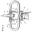
- FIG. 4 shows another embodiment of suction cup assembly of this invention.
- Tee-connector 40 attached to the lower end of the rod 10, and a sleeve 41 secured to that connector by nut 42.
- a collar 43 is slidable within the sleeve, and is retained by a circlip 44 at the lower end of the sleeve.
- the cup 11 is mounted centrally on the collar 43 and a compression spring 45 serves to bias the collar 43 into engagement with the circlip 44.
- a pair of flexible pipes 46 serve to interconnect the Tee-connector 40 provided at the lower end of the rod 10 with a similar connector 47 fitted to the mounting boss at the upper end of the cup 11, to communicate with the interior thereof. In this way, air may be drawn through the cup 11 by applying a reduced pressure to the rod 10.
- the pipes 46 pass between the turns of the spring 45 adjacent the connector 47 and through apertures 48 formed in the sleeve 40.
- the cup will partially compress but will also pivot, about the point of contact between the collar 43 and the circlip 44, diametrically opposed to the effective point of application of force A.
- the collar 43 may also slide linearly within the sleeve 41, and so the spring 45 affords a degree of compliance to the coupling, which may serve to absorb forces which would otherwise be imparted to a mushroom cap being harvested upon downward movement of the assembly, as a whole, to contact that cap.
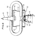
- FIG. 5 shows a third embodiment of suction cup assembly of this invention, somewhat similar to that shown in Figure 4, and insofar as the two embodiments utilise similar components, those components are given like reference characters and will not be described in detail again here.
- a sleeve 50 Mounted on the lower end of the upper Tee-connector 40 is a sleeve 50 having apertures 51 through which the vacuum pipes 46 pass, to communicate with the lower Tee-connector 47 and so with the interior of the suction cup 11.
- a flexible rubber membrane 52 Stretched across the lower end of the sleeve 50 is a flexible rubber membrane 52, held in place by means of an external O-ring 53, received partially within an annular groove formed in the outer surface of the sleeve 50, adjacent its lower end.
- the membrane 52 has a central aperture, and the edges of that membrane defining the aperture are received in a groove 54, formed in a mounting boss 55 provided at the upper end of the suction cup 11.
- this fourth embodiment of the invention behaves in a generally similar manner to that described above, for the other embodiments.
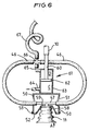
- Figure 6 shows a modification of the third embodiment illustrated in Figure 5 and like components are given like reference characters and will not be described in detail again here.
- a skirt 58 of a light-weight rigid material (such as aluminium) is secured to the upper end of the cup 11, so as to surround part of the axial length of the cup.
- the skirt is of a conical shape and its depth is selected so that the plane of the free part of the membrane 52 lies part-way between the ends of the cup 11, and approximately in the plane of the mouth of the cup, when compressed.
- the cup is advantageously fitted to the sleeve 52 by positioning the skirt 58 within the sleeve, and then laying the membrane 52 over the sleeve, the membrane having only a small central opening for the Tee-connector 47.
- the cup may be offered to the membrane and the skirt 58 pulled down, for example by means of bolts (not shown) fitted internally within the cup, and threaded into the top wall 59 of the skirt. This has the advantage of uniformly tensioning the membrane and clamping it to the cup.
- the assembly shown in Figure 6 includes a piston rod 60 is attached co-axially to the lower end of the support rod 10.
- the piston rod 60 is a part of a ram 61 including a piston 62 mounted on rod 60 and a cylinder 63.
- the sleeve 50 is mounted on the lower end of the cylinder 63 and the space C within the cylinder, between the piston 62 and the sleeve 50, is vented to atmosphere through port 64.
- the space D within the ram between the piston 62 and the upper end of the cylinder 63 is connected through port 65 to a four-way connector 66, two of the arms of which receive the flexible pipes 46 communicating with the interior of the cup 11.
- the fourth arm of the connector 66 receives a further flexible pipe 67, communicating with a pressure source (not shown) selectable between sub-atmospheric pressure and super-atmospheric pressure.
- Deflection of the cup 11 occurs in the same manner as has been described above with reference to Figure 5, should a one-sided force be applied thereto.
- a low-pressure source is connected to pipe 67, a reduced pressure exists within chamber D, due to the pressure drop in the pipes 46 and across any filter which may be provided within the cup 11 - for example, a block of porous foamed material (not shown).
- This reduced pressure will cause the ram 61 to move to its fully extended position but since the pressure drop within the pipes 46 is relatively small, the ram will be extended with only a relatively small force.
- the ram 61 may contract against the force provided by the reduced pressure in chamber D, so giving compliance to the system, in addition to the pivotal compliance afforded by the rubber membrane 52.
- the pressure in chamber D will fall so as subsequently to hold the ram in the fully extended position, during the harvesting of the mushroom and on subsequent movement thereof to a discharge site.
- a super-atmospheric pressure source may be connected to the pipe 67, so blowing the mushroom free from the cup 11 and simultaneously applying pressure to chamber D of the ram, causing the ram to contract and so lift the suction cup 11 clear of the released mushroom.
Landscapes
- Life Sciences & Earth Sciences (AREA)
- Engineering & Computer Science (AREA)
- Mechanical Engineering (AREA)
- Mycology (AREA)
- Environmental Sciences (AREA)
- Hooks, Suction Cups, And Attachment By Adhesive Means (AREA)
- Valve-Gear Or Valve Arrangements (AREA)
- Sheets, Magazines, And Separation Thereof (AREA)
- Transition And Organic Metals Composition Catalysts For Addition Polymerization (AREA)
- Non-Positive Displacement Air Blowers (AREA)
- Table Devices Or Equipment (AREA)
- Harvesting Machines For Specific Crops (AREA)
- External Artificial Organs (AREA)
- Separation Using Semi-Permeable Membranes (AREA)
- Manipulator (AREA)
Claims (10)
- Ensemble à ventouse comprenant une ventouse (11) ayant à une extrémité de celle-ci (24) une embouchure ouverte pour venir en contact avec un article, la ventouse (11) étant compressible dans sa direction axiale, un organe support (10) et un accouplement par lequel l'autre extrémité (23) de la ventouse est montée sur une partie terminale de l'organe (10), l'accouplement étant agencé pour permettre à la ventouse d'effectuer un mouvement général de pivotement par rapport à l'axe de l'organe, caractérisé en ce que l'accouplement comprend des moyens pour définir le centre effectif (25) dudit mouvement général de pivotement pour l'amener à se trouver à l'intérieur des contours de la ventouse (11) lorsque la ventouse est au moins partiellement comprimée d'un côté (A).
- Ensemble à ventouse selon la revendication 1, dans lequel le centre effectif (25) dudit mouvement de pivotement est agencé pour s'étendre sensiblement dans le plan de l'embouchure de la ventouse (11).
- Ensemble à ventouse selon la revendication 1 ou 2, dans lequel ledit accouplement comprend un manchon (50) monté sur la partie terminale de l'organe support (10), une membrane élastique (52) s'étendant sur l'extrémité du manchon (50) éloignée de l'organe support (10) et ladite autre extrémité de la ventouse (11), étant portée par la membrane (52) de façon que la ventouse puisse effectuer un mouvement général de pivotement par rapport à l'axe de l'organe support par déformation élastique de la membrane.
- Ensemble à ventouse selon la revendication 3, dans lequel la membrane (52) possède une ouverture centrale et la ventouse est montée dans ladite ouverture.
- Ensemble à ventouse selon la revendication 3, dans lequel il est prévu pour la ventouse (11) une jupe (58) qui s'étend à partir de ladite autre extrémité de la ventouse vers l'extrémité de l'embouchure de la ventouse, la membrane (52) s'étendant entre le manchon (50) et l'extrémité libre de la jupe (58).
- Ensemble à ventouse selon la revendication 1 ou 2, dans lequel ledit accouplement comprend un premier mécanisme à quatre barres articulé en trapèze possédant une paire de barres de longueur différente (13, 14) normalement parallèles, dont la barre la plus longue (13) est montée sur l'organe support (10), et un second mécanisme à quatre barres articulé en trapèze possédant également une paire de barres de longueur différente (16, 17) normalement parallèles dont la barre la plus longue (16) est montée sur la barre la plus courte (14) du premier mécanisme et sensiblement à angle droit par rapport à celle-ci, la ventouse (11) étant montée sur la barre la plus courte (17) du second mécanisme et les projections des barres de longueur égale (15, 18) du premier et du second mécanisme se coupant toutes, normalement, sensiblement en un point (25), des moyens de rappel (21) étant prévus pour appliquer aux mécanismes une force élastique de rappel tendant à maintenir sensiblement parallèles les barres de longueur inégale (13, 14 ; 16, 17) des deux mécanismes, de sorte que la ventouse (11) puisse effectuer un mouvement général de pivotement par rapport à l'axe de l'organe support.
- Ensemble à ventouse selon l'une quelconque des revendications précédentes, dans lequel l'accouplement comprend des moyens (61) rappelant la ventouse (11) à l'écart de l'organe support.
- Ensemble à ventouse selon la revendication 7, dans lequel les moyens de rappel (61) comprennent un vérin (62, 63) disposé entre l'organe support (10) et la ventouse (11), ce vérin étant adapté (65, 67) à être relié à une source de basse pression de telle manière que le vérin s'étire lorsqu'une basse pression lui est appliquée.
- Ensemble à ventouse selon la revendication 8, dans lequel une seule source de basse pression est reliée au vérin et à la ventouse, au moyen d'une ligne de basse pression commune (67) conduisant à l'ensemble à ventouses.
- Ensemble à ventouse selon la revendication 1 ou 2, dans lequel ledit accouplement comprend un manchon (41) monté sur la partie terminale de l'organe support (10), un collier (43) disposé de manière coulissante et basculante dans le manchon (41) et un ressort (45) rappelant le collier (43) à l'écart de l'organe support (10), la ventouse (11) étant montée sur le collier (43) de sorte que la ventouse peut effectuer un mouvement général de pivotement relativement à l'axe de l'organe support (10) par basculement du collier (43) à l'intérieur du manchon (41).
Applications Claiming Priority (3)
| Application Number | Priority Date | Filing Date | Title |
|---|---|---|---|
| GB9203766 | 1992-02-21 | ||
| GB929203766A GB9203766D0 (en) | 1992-02-21 | 1992-02-21 | Suction cup assemblies |
| PCT/GB1993/000342 WO1993016582A1 (fr) | 1992-02-21 | 1993-02-18 | Systeme de ventouse |
Publications (2)
| Publication Number | Publication Date |
|---|---|
| EP0626801A1 EP0626801A1 (fr) | 1994-12-07 |
| EP0626801B1 true EP0626801B1 (fr) | 1997-08-13 |
Family
ID=10710829
Family Applications (1)
| Application Number | Title | Priority Date | Filing Date |
|---|---|---|---|
| EP93904226A Expired - Lifetime EP0626801B1 (fr) | 1992-02-21 | 1993-02-18 | Systeme de ventouse |
Country Status (11)
| Country | Link |
|---|---|
| US (1) | US5491965A (fr) |
| EP (1) | EP0626801B1 (fr) |
| JP (1) | JPH07503854A (fr) |
| AT (1) | ATE156652T1 (fr) |
| AU (1) | AU680192B2 (fr) |
| CA (1) | CA2130557A1 (fr) |
| DE (1) | DE69313101T2 (fr) |
| GB (1) | GB9203766D0 (fr) |
| NZ (1) | NZ249198A (fr) |
| WO (1) | WO1993016582A1 (fr) |
| ZA (1) | ZA931125B (fr) |
Families Citing this family (24)
| Publication number | Priority date | Publication date | Assignee | Title |
|---|---|---|---|---|
| NL9101205A (nl) * | 1991-07-09 | 1993-02-01 | Ccm Beheer Bv | Inrichting en werkwijze voor het automatisch selectief oogsten van champignons. |
| FR2784854B1 (fr) * | 1998-10-26 | 2000-12-29 | Legle Systemes | Machine a desolidariser les champignons |
| DE19929510A1 (de) * | 1999-06-29 | 2001-01-04 | Wiesenhof Pilzland Vertriebsgm | Verfahren und Vorrichtung zum Bearbeiten von Pilzen o. dgl. |
| FR2800721B1 (fr) * | 1999-11-08 | 2002-02-08 | Elf Lubrifiants | Dispositif de prehension et de deplacement d'un objet presentant une face partiellement plane |
| GB0218125D0 (en) * | 2002-08-05 | 2002-09-11 | Mckeown Colm | A robot harvesting system |
| US20110095551A1 (en) * | 2009-10-28 | 2011-04-28 | Larry Downs | Device for pickup and transfer of frozen food items |
| FR2973846B1 (fr) * | 2011-04-11 | 2013-05-24 | Airfan | Appareil de delivrance regulee d'un gaz, notamment appareil d'assistance respiratoire |
| JP5978081B2 (ja) * | 2012-09-19 | 2016-08-24 | 樋脇 就三 | 切断機 |
| US10336562B2 (en) | 2013-05-17 | 2019-07-02 | Intelligrated Headquarters, Llc | Robotic carton unloader |
| US9650215B2 (en) | 2013-05-17 | 2017-05-16 | Intelligrated Headquarters Llc | Robotic carton unloader |
| EP2996973B1 (fr) | 2013-05-17 | 2019-01-30 | Intelligrated Headquarters LLC | Déchargeur robotique de cartons |
| US9487361B2 (en) | 2013-05-17 | 2016-11-08 | Intelligrated Headquarters Llc | Robotic carton unloader |
| US9493316B2 (en) | 2013-07-30 | 2016-11-15 | Intelligrated Headquarters Llc | Robotic carton unloader |
| CN105531207B (zh) | 2013-08-28 | 2018-06-08 | 因特利格兰特总部有限责任公司 | 纸箱卸载机器人 |
| US9623569B2 (en) | 2014-03-31 | 2017-04-18 | Intelligrated Headquarters, Llc | Autonomous truck loader and unloader |
| US10597235B2 (en) | 2016-10-20 | 2020-03-24 | Intelligrated Headquarters, Llc | Carton unloader tool for jam recovery |
| CN109349006B (zh) * | 2018-09-30 | 2023-07-28 | 山东省农业科学院农业资源与环境研究所 | 一种高效金针菇采收-废料回收系统及方法 |
| CN112960393B (zh) * | 2021-02-09 | 2022-08-09 | 河南科技大学 | 一种双孢菇抓取装置用末端执行器 |
| CN113213158B (zh) * | 2021-05-28 | 2024-07-02 | 南通安泰机械有限公司 | 一种无动力可调节负压真空吸盘式连接器 |
| EP4380348B1 (fr) * | 2021-08-03 | 2026-03-04 | 4Ag Robotics Inc. | Effecteur terminal pour un système automatisé de récolte de champignons |
| US11856898B2 (en) * | 2021-08-03 | 2024-01-02 | 4Ag Robotics Inc. | Automated mushroom harvesting system |
| WO2025091105A1 (fr) | 2023-10-30 | 2025-05-08 | 4Ag Robotics Inc. | Récolte activée par virtualisation par apprentissage automatique |
| WO2025166444A1 (fr) | 2024-02-08 | 2025-08-14 | 4Ag Robotics Inc. | Changeur d'outil activé par apprentissage automatique pour système de gestion de culture de champignons |
| US12377567B1 (en) | 2024-11-22 | 2025-08-05 | 4Ag Robotics Inc. | Mushroom trimming and sorting system |
Family Cites Families (4)
| Publication number | Priority date | Publication date | Assignee | Title |
|---|---|---|---|---|
| US3183640A (en) * | 1962-05-29 | 1965-05-18 | Gen Box Distributors | Cantaloupe packing machine |
| DE3036116C2 (de) * | 1980-09-25 | 1987-03-19 | F & O Electronic Systems GmbH & Co, 6901 Neckarsteinach | Vorrichtung zum Anheben und Transportieren von stückigem Schüttgut |
| GB2237491B (en) * | 1989-11-03 | 1993-12-22 | Priorlucky Ltd | Harvesting of delicate produce |
| US5185989A (en) * | 1990-05-04 | 1993-02-16 | Priorlucky Limited | Mushroom harvesting |
-
1992
- 1992-02-21 GB GB929203766A patent/GB9203766D0/en active Pending
-
1993
- 1993-02-09 US US08/290,963 patent/US5491965A/en not_active Expired - Fee Related
- 1993-02-18 DE DE69313101T patent/DE69313101T2/de not_active Expired - Fee Related
- 1993-02-18 AU AU35093/93A patent/AU680192B2/en not_active Ceased
- 1993-02-18 CA CA002130557A patent/CA2130557A1/fr not_active Abandoned
- 1993-02-18 AT AT93904226T patent/ATE156652T1/de not_active IP Right Cessation
- 1993-02-18 JP JP5514629A patent/JPH07503854A/ja active Pending
- 1993-02-18 NZ NZ249198A patent/NZ249198A/en unknown
- 1993-02-18 EP EP93904226A patent/EP0626801B1/fr not_active Expired - Lifetime
- 1993-02-18 WO PCT/GB1993/000342 patent/WO1993016582A1/fr not_active Ceased
- 1993-02-18 ZA ZA931125A patent/ZA931125B/xx unknown
Also Published As
| Publication number | Publication date |
|---|---|
| ATE156652T1 (de) | 1997-08-15 |
| AU3509393A (en) | 1993-09-13 |
| CA2130557A1 (fr) | 1993-09-02 |
| US5491965A (en) | 1996-02-20 |
| NZ249198A (en) | 1997-02-24 |
| ZA931125B (en) | 1993-12-08 |
| GB9203766D0 (en) | 1992-04-08 |
| JPH07503854A (ja) | 1995-04-27 |
| WO1993016582A1 (fr) | 1993-09-02 |
| DE69313101T2 (de) | 1998-03-19 |
| DE69313101D1 (de) | 1997-09-18 |
| AU680192B2 (en) | 1997-07-24 |
| EP0626801A1 (fr) | 1994-12-07 |
Similar Documents
| Publication | Publication Date | Title |
|---|---|---|
| EP0626801B1 (fr) | Systeme de ventouse | |
| US6419211B1 (en) | Manipulator and method for manufacturing the manipulator | |
| US3957263A (en) | Telescopic suction member for feeding sheet material | |
| US4975016A (en) | Automated machine for detection and grasping of objects | |
| US5054831A (en) | Piercing element gripping apparatus | |
| EP0593680B1 (fr) | Dispositif servant a recolter automatiquement et selectivement les champignons | |
| US5882055A (en) | Probe for handling microchips | |
| US3982782A (en) | Vacuum lifting apparatus for cylindrical articles | |
| US3596972A (en) | Tree clamp structure | |
| US4045073A (en) | Device for displacing an egg-tray | |
| US5185989A (en) | Mushroom harvesting | |
| EP0156492B1 (fr) | Grapping d'enveloppement | |
| US4635988A (en) | Procedure and device for gripping parcels | |
| IE911515A1 (en) | Mushroom harvesting | |
| CN109703856B (zh) | 一种自适应泵体贴标抚平装置 | |
| CN109429722A (zh) | 一种变刚度仿人手软体自适应性抓取装置 | |
| CN109005912A (zh) | 一种草莓柔性采摘的末端执行装置 | |
| CN223968295U (zh) | 一种采摘柔性作物的末端执行器 | |
| JPH09109077A (ja) | ロボットハンド用指 | |
| CA1262431A (fr) | Mecanisme de manutention de grumes | |
| US7571799B2 (en) | Feeding station for processing bulbous flowers | |
| JP2003011077A (ja) | 吸着カップ装置 | |
| JP2587727B2 (ja) | 吸着式ロボットハンド | |
| CN223958045U (zh) | 用于花椒簇采摘的多角度转动机械臂 | |
| SU1111977A1 (ru) | Вакуумный захват |
Legal Events
| Date | Code | Title | Description |
|---|---|---|---|
| PUAI | Public reference made under article 153(3) epc to a published international application that has entered the european phase |
Free format text: ORIGINAL CODE: 0009012 |
|
| 17P | Request for examination filed |
Effective date: 19940912 |
|
| AK | Designated contracting states |
Kind code of ref document: A1 Designated state(s): AT BE CH DE DK ES FR GB GR IE IT LI LU NL PT SE |
|
| 17Q | First examination report despatched |
Effective date: 19950818 |
|
| GRAG | Despatch of communication of intention to grant |
Free format text: ORIGINAL CODE: EPIDOS AGRA |
|
| GRAH | Despatch of communication of intention to grant a patent |
Free format text: ORIGINAL CODE: EPIDOS IGRA |
|
| GRAH | Despatch of communication of intention to grant a patent |
Free format text: ORIGINAL CODE: EPIDOS IGRA |
|
| GRAA | (expected) grant |
Free format text: ORIGINAL CODE: 0009210 |
|
| AK | Designated contracting states |
Kind code of ref document: B1 Designated state(s): AT BE CH DE DK ES FR GB GR IE IT LI LU NL PT SE |
|
| PG25 | Lapsed in a contracting state [announced via postgrant information from national office to epo] |
Ref country code: LI Effective date: 19970813 Ref country code: IT Free format text: LAPSE BECAUSE OF FAILURE TO SUBMIT A TRANSLATION OF THE DESCRIPTION OR TO PAY THE FEE WITHIN THE PRESCRIBED TIME-LIMIT;WARNING: LAPSES OF ITALIAN PATENTS WITH EFFECTIVE DATE BEFORE 2007 MAY HAVE OCCURRED AT ANY TIME BEFORE 2007. THE CORRECT EFFECTIVE DATE MAY BE DIFFERENT FROM THE ONE RECORDED. Effective date: 19970813 Ref country code: GR Free format text: LAPSE BECAUSE OF FAILURE TO SUBMIT A TRANSLATION OF THE DESCRIPTION OR TO PAY THE FEE WITHIN THE PRESCRIBED TIME-LIMIT Effective date: 19970813 Ref country code: ES Free format text: THE PATENT HAS BEEN ANNULLED BY A DECISION OF A NATIONAL AUTHORITY Effective date: 19970813 Ref country code: DK Free format text: LAPSE BECAUSE OF NON-PAYMENT OF DUE FEES Effective date: 19970813 Ref country code: CH Effective date: 19970813 Ref country code: AT Effective date: 19970813 |
|
| REF | Corresponds to: |
Ref document number: 156652 Country of ref document: AT Date of ref document: 19970815 Kind code of ref document: T |
|
| REG | Reference to a national code |
Ref country code: CH Ref legal event code: EP |
|
| REF | Corresponds to: |
Ref document number: 69313101 Country of ref document: DE Date of ref document: 19970918 |
|
| PG25 | Lapsed in a contracting state [announced via postgrant information from national office to epo] |
Ref country code: SE Effective date: 19971113 |
|
| PG25 | Lapsed in a contracting state [announced via postgrant information from national office to epo] |
Ref country code: PT Effective date: 19971118 |
|
| ET | Fr: translation filed | ||
| PG25 | Lapsed in a contracting state [announced via postgrant information from national office to epo] |
Ref country code: LU Free format text: LAPSE BECAUSE OF NON-PAYMENT OF DUE FEES Effective date: 19980218 |
|
| REG | Reference to a national code |
Ref country code: CH Ref legal event code: PL |
|
| PLBE | No opposition filed within time limit |
Free format text: ORIGINAL CODE: 0009261 |
|
| STAA | Information on the status of an ep patent application or granted ep patent |
Free format text: STATUS: NO OPPOSITION FILED WITHIN TIME LIMIT |
|
| 26N | No opposition filed | ||
| REG | Reference to a national code |
Ref country code: GB Ref legal event code: IF02 |
|
| PGFP | Annual fee paid to national office [announced via postgrant information from national office to epo] |
Ref country code: IE Payment date: 20020205 Year of fee payment: 10 |
|
| PGFP | Annual fee paid to national office [announced via postgrant information from national office to epo] |
Ref country code: BE Payment date: 20020218 Year of fee payment: 10 |
|
| PGFP | Annual fee paid to national office [announced via postgrant information from national office to epo] |
Ref country code: FR Payment date: 20020228 Year of fee payment: 10 |
|
| PGFP | Annual fee paid to national office [announced via postgrant information from national office to epo] |
Ref country code: GB Payment date: 20030214 Year of fee payment: 11 |
|
| PG25 | Lapsed in a contracting state [announced via postgrant information from national office to epo] |
Ref country code: IE Free format text: LAPSE BECAUSE OF NON-PAYMENT OF DUE FEES Effective date: 20030218 |
|
| PG25 | Lapsed in a contracting state [announced via postgrant information from national office to epo] |
Ref country code: BE Free format text: LAPSE BECAUSE OF NON-PAYMENT OF DUE FEES Effective date: 20030228 |
|
| PGFP | Annual fee paid to national office [announced via postgrant information from national office to epo] |
Ref country code: NL Payment date: 20030228 Year of fee payment: 11 |
|
| PGFP | Annual fee paid to national office [announced via postgrant information from national office to epo] |
Ref country code: DE Payment date: 20030422 Year of fee payment: 11 |
|
| PG25 | Lapsed in a contracting state [announced via postgrant information from national office to epo] |
Ref country code: FR Free format text: LAPSE BECAUSE OF NON-PAYMENT OF DUE FEES Effective date: 20031031 |
|
| REG | Reference to a national code |
Ref country code: FR Ref legal event code: ST |
|
| REG | Reference to a national code |
Ref country code: IE Ref legal event code: MM4A |
|
| PG25 | Lapsed in a contracting state [announced via postgrant information from national office to epo] |
Ref country code: GB Free format text: LAPSE BECAUSE OF NON-PAYMENT OF DUE FEES Effective date: 20040218 |
|
| PG25 | Lapsed in a contracting state [announced via postgrant information from national office to epo] |
Ref country code: NL Free format text: LAPSE BECAUSE OF NON-PAYMENT OF DUE FEES Effective date: 20040901 Ref country code: DE Free format text: LAPSE BECAUSE OF NON-PAYMENT OF DUE FEES Effective date: 20040901 |
|
| GBPC | Gb: european patent ceased through non-payment of renewal fee |
Effective date: 20040218 |
|
| NLV4 | Nl: lapsed or anulled due to non-payment of the annual fee |
Effective date: 20040901 |