EP0626873B1 - Vorrichtung zum verändern der natürlichen druckverteilung eines skis auf seine gleitfläche und skibremse - Google Patents
Vorrichtung zum verändern der natürlichen druckverteilung eines skis auf seine gleitfläche und skibremse Download PDFInfo
- Publication number
- EP0626873B1 EP0626873B1 EP93901793A EP93901793A EP0626873B1 EP 0626873 B1 EP0626873 B1 EP 0626873B1 EP 93901793 A EP93901793 A EP 93901793A EP 93901793 A EP93901793 A EP 93901793A EP 0626873 B1 EP0626873 B1 EP 0626873B1
- Authority
- EP
- European Patent Office
- Prior art keywords
- ski
- base
- stiffening member
- levers
- blade
- Prior art date
- Legal status (The legal status is an assumption and is not a legal conclusion. Google has not performed a legal analysis and makes no representation as to the accuracy of the status listed.)
- Expired - Lifetime
Links
Images




Classifications
-
- A—HUMAN NECESSITIES
- A63—SPORTS; GAMES; AMUSEMENTS
- A63C—SKATES; SKIS; ROLLER SKATES; DESIGN OR LAYOUT OF COURTS, RINKS OR THE LIKE
- A63C5/00—Skis or snowboards
- A63C5/06—Skis or snowboards with special devices thereon, e.g. steering devices
- A63C5/075—Vibration dampers
-
- A—HUMAN NECESSITIES
- A63—SPORTS; GAMES; AMUSEMENTS
- A63C—SKATES; SKIS; ROLLER SKATES; DESIGN OR LAYOUT OF COURTS, RINKS OR THE LIKE
- A63C9/00—Ski bindings
Definitions
- the invention relates to a device for modifying the natural pressure distribution of a ski, such as that in particular an alpine ski on its sliding surface, as well as a ski brake.
- the invention also relates to a ski, in particular an alpine ski, which is equipped with a device aimed at modify its pressure distribution on its sliding surface.
- the skis which are used for the practice of alpine skiing consist of boards relatively long, on which the skier's shoes are retained, most often by elements of front and rear fixing. Shoes and fasteners are approximately in the middle area of the ski, which is commonly called the skate.
- the skis present in themselves, at rest, a natural camber. They also present a some flexibility. When skiing, the ski deforms elastically to respond to different stresses to which it is subjected on the part of the skier, and by reaction, of the surface on which it slides.
- the main stress to which the ski is subjected, from the skier, is generated by the weight of the skier. This weight is located approximately in the area of the ski skate.
- the ski is also stressed by the binding elements. It is indeed known that the elements of fastening pinch the shoe. To do this, the rear fixing element is generally mounted sliding, and it is elastically recalled forward by springs which are called springs step back. The reaction to this pinching action is transmitted by the binding elements to the ski. This reaction is different, however, depending on whether the front fastener and the fastener rear are each secured to the ski, or else the front fastening element is secured to the ski, and the rear fixing element is connected to the front fixing element by inextensible means, such as than a blade.
- ski can be made more or less pivoting or more or less guiding, that is, one can promote one's ability to turn easily or to present a high driving stability.
- the pressure distribution of the ski on the snow is determined mainly by the internal structure of the ski, and by the method of assembling the elements binding to the ski, that is to say with or without connecting blade between the front and rear elements.
- the pressure distribution can also be influenced by the thrust intensity given to the spring step back.
- European patent application No. 183 586 describes a blade of elastic material attached above the ski, between the binding elements and the ski. This blade has, at its front end and its rear end, sliders through which a portion of the forces to which the ski is subjected passes vertically.
- This device however has the disadvantage of having modest performance, for a large size. It is suitable for the case where both feet of the skier are in support for the same ski, to avoid that the whole weight of the skier is concentrated in the skate area. On the other hand, it would be ill-suited in the case of a pair of traditional skis.
- One of the aims of the present invention is to propose a device which overcomes these drawbacks, and which allows the ski to be preloaded in an adjustable manner in front and behind the skate area.
- the French patent application published under the number FR 2 513 132 describes a brake the actuation pedal of which comprises two levers hinged together at their adjacent end.
- One of the levers is also articulated to a base secured to the ski.
- the other lift carries arms of brake, and it is connected to the base at a light oriented longitudinally.
- a spring exerts a restoring force on the movable end of this lever, which tends to fold the two levers one against each other.
- this device has no significant influence on skiing. Indeed, it is of relatively small dimensions, in addition all the longitudinal forces are transmitted by reaction to a single piece, that is to say the base. Therefore, these efforts do not affect the structure of the ski.
- Another object of the present invention is to provide a device which has a space requirement reduced.
- Another object of the present invention is to provide a device which only influences so moderate flexibility of the skate during ski flexions.
- Another object of the present invention is to provide a device which generates on the ski a bending stress only when the ski is used.
- the device according to the invention aims to modify the natural pressure distribution of a ski such that in particular an alpine ski on its sliding surface, the ski being intended to be used with a shoe.
- the device comprises a front base plate and a rear base plate provided to be joined to the ski in its central area, each of the base plates having a tip raised relative to the upper surface of the ski, a slender stiffening member incompressible which is intended to extend above the upper surface of the ski, the ends of the stiffening member being in abutment against the ends of the base plates.
- the ski brake is intended to brake the movement of a ski in the absence of the boot. he includes at least one brake arm designed to be mounted on the ski, and movable between a position work where the brake protrudes under the lower surface of the ski, and a rest position where the arm goes up along the side edges of the ski, comprising a movable actuating toggle between a flattened position and a folded position to control the movement of the brake arm and a spring reminder to resiliently apply the kneepad in its folded position corresponding to the working position of the brake arm. It is characterized by the fact that the two ends of the toggle are connected to the end caps of two brake base plates, the base plates being separate and designed to be assembled directly to the ski remotely.
- Figure 1 is a perspective view of a ski in its skate area, equipped, moreover, with a device according to a first implementation of the invention.
- FIG. 2 is a side view of the embodiment shown in FIG. 1.
- Figure 3 is a top view of the stiffening blade.
- Figure 4 is a side view of the rider who straddles the stiffening blade.
- FIG. 5 is a perspective view of a base plate associated with one of the elements of fixation.
- Figure 6 is a partial side view, in section, which illustrates the connection between the end of the blade stiffening and base plate.
- Figure 7 is a view similar to that of Figure 2, in another operating position of the device.
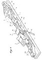
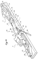
- FIG. 8 is a perspective view, in the skate area, of a ski equipped with a device according to a another embodiment of the invention.
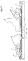
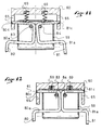
- FIG. 9 is a partial side view which illustrates the operation of the device present in the Figure 8, the fasteners are not shown in this figure.
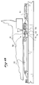
- Figure 10 is a view similar to Figure 9 in another operating position.
- Figures 11 and 12 illustrate the mode of retraction of the brake which equips the device of Figures 9 and 10.
- Figure 13 is a partial side view, in section, which illustrates an alternative embodiment of the device shown in Figures 9 and 10.
- FIG. 14 represents the spring which equips the device of FIG. 13.
- Figure 1 shows the skate area of a ski.
- the ski has in this zone a base 1, on which are mounted two front and rear fasteners 2 and 3.
- These fasteners are of any suitable type, and they usually include a jaw which retains the front end or rear of the shoe, and which is movable against the restoring force of an elastic return mechanism.
- the front fixing element 2 also has a base 6 by which it is secured to the ski, by any suitable means, and for example by screwing.
- a support plate 4 is, moreover, located in the rear part of the base 6, and this support plate is intended to receive the end front of the shoe sole.
- the rear fastening element 3 has in known manner a movable body along a slide 7, the slide itself being secured to the base 1 by any suitable means, for example by screwing.
- the front part of the slide has a support plate 5 which is intended to receive the end rear of the shoe sole.
- a braking device 9 is, moreover, associated with the rear fixing element 3.
- This device is of a known type, and in particular it comprises at least one, and preferably two braking arms 10, 11, which are movable between a working position where they protrude below the lower surface of the base 1 of the ski, and a rest position where they rise above the upper surface of the base.
- An actuating device 12 sensitive to the presence or absence of shoes also controls the passage of the brake arms to the rest position when the shoe is engaged in the fasteners.
- the actuation device is a pedal which is connected to the brake arm 10 and 11 by links 14, these links constituting in fact the extension of the brake arms 10 and 11 above the upper surface of the ski base.
- a known elastic return device also ensures the return of the brake arms to the position of work where they make room under the lower surface of the ski.
- This elastic return device elastically opposes the movement of the brake arms of their working position to their rest position.
- the device shown in the figures also has a stiffening member consisting by a stiffening blade 15 which extends above the upper surface of the base 1 according to a longitudinal direction.
- the central part of the blade 15 extends flat against the upper surface of the base 1, approximately between the front fixing element 2 and the rear fixing element 3.
- the ends of the blade are raised relative to the upper surface of the base 1, and they are supported in an approximately longitudinal direction against stops integral with the base. The blade exerts on these stops a thrust oriented towards the ends of the base.
- the blade 15 is incompressible in a longitudinal direction, and it also has elastic flexural qualities in the vertical and longitudinal median plane which it defines. It is carried out in any suitable material, and, for example, in a composite material possibly charged with fibers.
- the blade 15 which is shown in Figures 1 to 7 is a single continuous piece which has a constant thickness.
- the blade 15 has two parts, a front part 16 of constant width, and a rear part 17 also of constant width, but greater than that of part 16.
- the two parts 16 and 17 are separated by a shoulder zone 18.
- a rider 20 secured to the ski overlaps, moreover, the blade 15 in its part 16.
- the rider 20 has in its part lower a recess 21 whose dimensions correspond to that of a cross section of the part 16.
- the rider 20 preserves the blade from buckling in its front part 16.
- the front and rear ends 22 and 23 of the blade are supported in a direction approximately longitudinal against a stop integral with the ski.
- FIG. 5 represents such a stop for the rear fixing element 3 in the form of a base plate 25, which has a plate 26 intended to be interposed between the slide 7 and the upper surface of the base 1.
- a stirrup 29 extends in a direction overall inclined, so that the central part 30 of the stirrup is raised relative to the upper surface of the base 1.
- This central part 30 is pierced in a longitudinal direction, a tapped hole 31 in which a threaded plug 32 is screwed to a depth which can be variable.
- the plug 32 is equipped with a tip 33, which has a notch 34 in which the raised end 23 of the blade comes to bear in a direction approximately longitudinal.
- the plate 26 has, moreover, in its lower part, a longitudinal groove 34 whose dimensions correspond to those of a cross section of the rear part 17 of the blade.
- the plate 26 is in two parts, a rear part which carries the stirrup 29, and a front part independent of the rear part, which in fact plays the role of shim thickness.
- a base plate 35 of the same type At the front fastening element 2 is a base plate 35 of the same type, with a plate 36 interposed between the base 6 of the binding element 2, and the base 1 of the ski. Platinum 36 forwards a stirrup 39, with a central part 40 which is fitted with a plug 42. The front end 22 of the blade bears against a tip 43 movable in a direction longitudinal with the rotation of the plug 42.
- the plate 36 has, in addition, a longitudinal groove 44 whose dimensions are substantially the same as those of a cross section of the front part 16 of the blade.
- the distance between the two end pieces 33 and 43 of the front and rear base plates is substantially equal to the length of the blade 15.
- the buckling zone 17a and the actuation pedal 12 of the braking device are provided for cooperate together, that is to say that when the actuation pedal is driven down by the shoe sole, it presses against the buckling area, so as to flatten this area and forcing the blade to expand against each base plate 25, 35.
- a shoe shown diagrammatically at 50 is engaged between the elements of front and rear attachment 2 and 3.
- the actuation pedal 12 of the braking device is located low position, between the sole of the shoe and the buckling zone 17a of the blade 15 which it presses against the upper surface of the base 1.
- the disappearance of the buckling of the zone 17a caused by the presence of the shoe 50, tends to increase the distance between the ends 22 and 23 of the blade, which are pressed against the front and rear base plates 25 and 35. This therefore causes in the blade 15 a compressive stress, which is transmitted to the base plates 25 and 35, and which induces a bending moment of the front end and the rear end of the base 1.
- a shim 49 is placed between the upper surface of the base 1 and the area 17a of the blade, to maintain a start of buckling when this zone 1 Ta is flattened by the pedal against the upper surface of the base 1 of the ski.
- the area 17a constitutes for the blade 17 taring means which induce in the blade a stress of compression.
- the determined value of the bending moments is also adjustable by screwing the threaded plugs 32 and 42 against which the ends 22 and 23 of the blade bear. More the caps 32 and 42 are screwed, plus the stress that the blade 15 exerts on the base at the decks 26 and 36 is strong.
- the rider 20 can also cooperate with the shoulder zone 18 presented by the blade 15, so that the blade induces a bending moment of different intensity towards the front and towards the rear of the ski. Indeed, if the jumper 20 is placed relative to the shoulder 18, so that the area shoulder 18 comes into contact with the rider 20 during the flattening of the flamed area 17a, part of the compressive stress that the blade 15 exerts towards the front of the ski is absorbed by the rider 20, and therefore does not reach the base plate 35. The blade 15 therefore exerts on the base plate 35 a lower pushing force than it exerts on the rear base plate 25. The bending moment induced on the front end of the ski is thus less than the bending moment armature on the back.
- the shoulder zone 18 could be located on the blade 15 immediately behind of plate 36, and cooperate with the front wall of this plate so that the blade transmits to forward a lower pushing force forward than backward.
- fastening elements 2 and 3 are connected to the base of the ski, and not to the stiffening blade. We therefore keep a very good contact between the base 1 and the sole of shoe, and a very good transmission of the stresses and forces which pass between the ski boot and base.
- FIG. 8 illustrates another embodiment of the invention, and more precisely a variant of the stiffening blade.
- FIG. 8 represents a base 1, a front fixing element 2 and a fixing element rear 3, which are identical to the elements previously described. Also, each element is equipped with a base plate 25, 35, which is identical to the previous base plates. Between the base plates 25 and 35 extends a stiffening member 55.
- the stiffening member 55 comprises a rear part 56, a front part 57, and a central toggle 58.
- the rear and front parts 56 and 57 are formed by blade portions which have qualities similar to the blade 15 previously described, that is to say qualities of incompressibility in a longitudinal direction and of elastic bending in a vertical plane.
- the rear part 56 extends from the base plate 25 to front of the fixing element 3, passing under the plate 26 associated with this fixing element, the same way as described above.
- the front portion 57 extends from the front base plate to behind the fixing element 2, passing under this fastening element.
- a toggle device also connects the front end of the rear blade portion to the rear end of the front blade portion.
- the device 58 in its embodiment shown in the figure, includes two levers 59 and 60, which extend in a direction longitudinal, and which are hinged together around a horizontal and transverse axis 61.
- Le lever rear 59 is articulated at the front end of the portion 56, around a horizontal and transverse axis 62.
- the front lever 60 is articulated around a horizontal and transverse axis 63 to the rear end of the blade portion 57.
- the ends of the blade portions 56 and 57, to which the levers 59 and 60 are connected are equipped with a tip piece 66 and 67, which cross axes 62 and 63 respectively.
- the axis 61 which connects the two levers 59 and 60 is carried by the lever 59, and it is movable according to the longitudinal direction of the lever 60 along a lumen 65 which is located in the rear part thereof.
- the lever 60 has, moreover, in its rear part at least one spring which pushes the axis 61 resiliently toward the rear end of the lumen 65.
- the lever 60 is extended beyond the axis 61 by a pallet 70 which covers the lift 59 when the knee brace 58 is in its flattened position.
- a stop lower 71 of the lever 60 prevents the hinge pin 61 from passing under the alignment of the other two axes 62 and 63, in such a way that the toggle never locks and tends permanently to open under the pushing force of the spring 69.
- the front end 74 of the lever 59 abuts against a stop surface 75, that the lever 60 has just behind the light 65. In this way, in the flattened position of the knee pad 58, it is possible to abut one against the other the two levers 59 and 60, according to a longitudinal direction.
- the stiffening member then exerts on the base plates 25 and 35 an elastic stress as long as there is still play, then a stress not elastic when the front end 74 of the lever 59 abuts against the abutment surface 75.
- the stiffening member then constrains the base elastically in a first phase of its bending and then not elastic.
- the toggle joint 58 therefore constitutes setting means which induce in the connecting member 51 a variable compressive stress depending on the presence or absence of the shoe.
- the base plates 25 and 35 are equipped, as in the previous case, with a adjustment cap 32 and 42.
- the front end 74 of the lever 59 will be or not in contact with the abutment surface 75 of the lever 60 in the flattened position of the toggle. If there is no contact, the stiffening member will generate, on the front and rear base plates, a force of thrust which will tend to increase with the ski flexes. These ski flexes tend, in fact, to bring the two portions 56 and 57 closer to each other, resulting in additional compression of the spring 69.
- stiffening member behaves like an incompressible blade of the same like what was described for blade 15.
- FIG. 8 illustrates a shoulder zone 68 which is capable of cooperating with the front face of the plate 36 according to the setting of the plugs 32 and 42.
- the lever 59 carries brake arms 80 and 81. These brake arms follow the rotational movements of the lever 59 around the axis 62.
- the FIG. 9 represents the lever 59 in the inclined position, which projects the brake arms 80 and 81 under the lower surface of the base 1.
- the lever 59 extends substantially along a horizontal direction, and the brake arms 80 and 81 are brought back above the upper surface ski.
- the knee brace 58 when brought into the flattened position, exerts two actions different. On the one hand, it generates a compressive stress in the stiffening member 55, and on the other hand, it brings the brake arms back from their working position to their rest position.
- means also cause the retraction of the brake, that is to say the bringing together of the arms 80 and 81 towards the longitudinal axis of the ski.
- the lever 59 is constructed in the manner of a hollow casing, inside which the arms brake 80 and 81 penetrate by transverse segments 80a, 81a, then exit by two segments 80c and 81c, substantially in alignment with each other, which constitute the horizontal axis 61 and transverse previously described. This axis runs through the light 65 of sunrise 60.
- the brake arms 80 and 81 are movable in the plane defined by the casing 59, and they are held at the level of the lateral openings which they pass through, as well as by two central pots 83 and 84.
- the spring 69 previously described is split, and each element presses on a segment 80c, 81c, arms 80 and 81.
- FIG. 11 corresponds to the open position of the toggle joint, and in this position the springs 69 elastically stress the brake arms 80 and 81 at the spacing.
- Figure 12 corresponds to the flattened position of the toggle. In this position, the ends segments 80c and 81c abut in the front part of the lumen 65, which forces the arms brake 80 and 81 to approach the longitudinal axis of the ski.
- FIG. 13 illustrates an alternative embodiment according to which the thrust spring 69 is replaced by a torsion spring 90.
- the two levers 91 and 92 are hinged together about an axis 93.
- the spring 90 has two windings coaxial with the articulation axis 93, one central loop 94 which bears against the segments 80c and 81c of the arms of the kidney, and two free ends 95 and 96 which, in turn, bear against the lever 60.
- the axis 93 is movable along a lumen 98 of the lever 91.
Landscapes
- Footwear And Its Accessory, Manufacturing Method And Apparatuses (AREA)
- Braking Arrangements (AREA)
- Floor Finish (AREA)
- Friction Gearing (AREA)
- Transmission Devices (AREA)
Claims (18)
- Vorrichtung zum Verändern der natürlichen Verteilung des Druckes eines Ski wie insbesondere eines Alpinski, auf seiner Gleitoberfläche, wobei der Ski dazu vorgesehen ist, mit einem Schuh benutzt zu werden, wobei die Vorrichtung eine vordere Basisplatte (25) und eine hintere Basisplatte (35) aufweist, die dazu vorgesehen sind, fest mit dem Ski in seinem zentralen Bereich verbunden zu sein, wobei jede der Basisplatten einen bezüglich der oberen Oberfläche des Ski erhöhten Ansatz (33) aufweist, und eine nicht zusammendrückbare langgestreckte Versteifungseinrichtung (15, 55), die dazu vorgesehen ist, sich über der oberen Oberfläche des Ski zu erstrecken, wobei die Enden der Versteifungseinrichtung in Abstützung gegen die Ansätze der Basisplatten sind,
dadurch gekennzeichnet, daßein zentraler Bereich (17a, 58) der Versteifungseinrichtung instabil und deformierbar gemäß einer vertikalen Richtung durch Knicken oder Umklappen von Hebeln ist,ein vertikal bewegliches Pedal (12, 70), das sich auf der Ebene des zentralen Bereiches befindet, vorgesehen ist, um die Sohle des Schuhes aufzunehmen,das Pedal zwischen einer unteren Position, wo es den zentralen Bereich der Versteifungseinrichtung dazu zwingt, sich abzuflachen, um in der Versteifungseinrichtung eine Druckbeanspruchung zu erzeugen, die durch Reaktion auf die Ansätze der Basisplatten übertragen wird, und einer oberen Position beweglich ist, wo es den zentralen Bereich der Versteifungseinrichtung freigibt, um die Druckbeanspruchung zu annulieren, unddaß eine Rückholfeder (9, 69, 90) auf elastische Weise das Pedal in seine obere Position zurückholt. - Vorrichtung gemäß Anspruch 1, dadurch gekennzeichnet, daß der zentrale Bereich der Versteifungseinrichtung (55) zwei Hebel (59, 60) aufweist, die untereinander um eine horizontale und transversale Achse (61) auf Art und Weise eines instabilen Kniegelenkes angelenkt sind, und daß das freie Ende jedes Hebels (59, 60) an dem Rest der Druckeirrichtung um eine transversale und horizontale Achse (62, 63) angelenkt ist.
- Vorrichtung gemäß Anspruch 2, dadurch gekennzeichnet, daß das bewegliche Pedal eine Palette (70) ist, die einen der Hebel des Kniegelenkes (60) verlängert.
- Vorrichtung gemäß Anspruch 3, dadurch gekennzeichnet, daß in der gestreckten Position des Kniegelenkes die beiden Hebel (59, 60) in Abstützung gegeneinander gemäß einer longitudinalen Richtung sind.
- Vorrichtung gemäß Anspruch 3, dadurch gekennzeichnet, daß die Anlenkachse (61) der beiden Hebel durch das Ende eines Hebels (59) getragen ist und daß sie an dem Ende beweglich ist, das dem anderen Hebel (60) benachbart ist, wo sie gleitend längs eines Langloches (65) montiert ist, das gemäß der longitudinalen Richtung des Hebels ausgerichtet ist, und daß zumindest eine Feder (69) elastisch die Achse (62) in Richtung des Endes des Langloches zurückholt, um das Kniegelenk in seine offene Position zurückzuholen.
- Vorrichtung gemäß Anspruch 3, dadurch gekennzeichnet, daß einer (59) der beiden Hebel (59, 60) zumindest einen Hebelarm (80, 81) trägt.
- Vorrichtung gemäß Anspruch 6, dadurch gekennzeichnet, daß einer (59) der Hebel ein Gehäuse ist, das die Bremsarme (80, 81) trägt und das in seiner Rotationsbewegung die Arme zwischen zwei Positionen mit sich nimmt, einer Arbeitsposition, in der die Arme nach unten vorstehen, und einer Ruheposition, in der die Arme sich in eine horizontale Position zurückziehen.
- Vorrichtung gemäß Anspruch 1, dadurch gekennzeichnet, daß die Versteifungseinrichtung ein kontinuierliches flexibles und nicht zusammendrückbares Versteifungsblatt (15) ist und daß der zentrale Bereich der Versteifungseinrichtung ein Bereich (17a) ist, in dem sich das Blatt auf natürliche Weise durch Knicken verformt.
- Vorrichtung gemäß Anspruch 8, dadurch gekennzeichnet, daß das Pedal (12) das Betätigungspedal einer Haltevorrichtung für eine Bremse ist, die so vorgesehen ist, daß sie einem hinteren Bindungselement (3) zugeordnet ist.
- Vorrichtung gemäß irgendeinem der vorangehenden Ansprüche, dadurch gekennzeichnet, daß ein Anschlag (20, 36), der dazu bestimmt ist, fest mit dem Ski verbunden zu sein, mit einer komplementären Anschlageinrichtung (18, 68) des Versteifungsblattes zusammenwirkt, um die Druckbeanspruchung zu begrenzen, die durch die Versteifungseinrichtung (15, 55) in Richtung einer der Basisplatten (25, 35) ausgeübt wird.
- Vorrichtung gemäß Anspruch 10, dadurch gekennzeichnet, daß der Anschlag, der dazu bestimmt ist, fest mit der Befestigungsplatte verbunden zu sein, ein Reiter (20) ist, der auf der Versteifungseinrichtung (15) reitet, und daß die Anschlageinrichtung des Blattes eine Schulter (18) ist, die dem Blatt eine Breite gibt, die größer als die der Öffnung (21) des Reiters ist.
- Vorrichtung gemäß Anspruch 11, dadurch gekennzeichnet, daß der Reiter die Platine (36) der Basisplatte (35) ist, die einem der Bindungselemente zugeordnet ist, und daß die Anschlageinrichtung ein Schulterbereich (68) eines Abschnittes (57) der Versteifungseinrichtung ist, dessen Breite größer als die der Öffnung (44) der Platine ist.
- Vorrichtung gemäß Anspruch 1, dadurch gekennzeichnet, daß longitudinale Einstelleinrichtungen (32, 42) vorgesehen sind, um die longitudinale Position der Ansätze (33) der Basisplatten (25, 35) einzustellen, gegen die die Enden der Versteifungseinrichtung in Abstützung sind.
- Skibremse, die dazu bestimmt ist, die Verschiebung eines Ski in Abwesenheit des Schuhes zu bremsen, die zumindest einen Bremsarm (80, 81) aufweist, der dazu vorgesehen ist, auf dem Ski montiert zu werden und der beweglich zwischen einer Arbeitsposition ist, in der die Bremse unter der unteren Oberfläche des Ski vorsteht, und einer Ruheposition, in der der Arm sich längs der seitlichen Ränder des Ski zurückzieht, die ein Betätigungskniegelenk (58) aufweist, das zwischen einer gestreckten Position und einer zurückgebogenen Position beweglich ist, um die Verschiebung des Bremsarmes (80, 81) und einer Rückholfeder zu betätigen, um auf elastische Weise das Kniegelenk in seiner zurückgebogenen Position entsprechend der Arbeitsposition des Bremsarmes zu beanspruchen, dadurch gekennzeichnet, daß die beiden Enden des Kniegelenkes mit den Ansätzen der beiden Basisplatten (25, 35) der Bremse verbunden sind, wobei die Basisplatten unterschiedlich sind und dazu yorgesehen sind, direkt an dem Ski auf distanzierte Weise montiert zu werden.
- Skibremse gemäß Anspruch 14, dadurch gekennzeichnet, daß das Betätigungskniegelenk eine Gesamtheit von zwei Hebeln (59, 60) aufweist, die untereinander um eine horizontale und transversale Achse (61) angelenkt sind, und daß einer (59) der Hebel die Bremsarme (80, 81) trägt.
- Skibremse gemäß Anspruch 15, dadurch gekennzeichnet, daß die Hebel (59, 60) Einrichtungen (80c, 81c, 65) aufweisen, um die Bremsarme (80, 81) der longitudinalen Achse der Befestigungsplatte (1) anzunähern, wenn die Bremsarme durch den Schuh in ihre Ruheposition zurückgeholt sind.
- Ski, insbesondere ein Ski, der zum Alpinskifahren bestimmt ist, der eine Befestigungsplatte (1) aufweist, auf der zumindest ein Bindungselement (3, 4) montiert ist, das dazu bestimmt ist, einen Schuh zu halten, dadurch gekennzeichnet, daß er außerdem eine Vorrichtung gemäß irgendeinem der Ansprüche 1 bis 13 aufweist, die dazu bestimmt ist, den Druck zu verteilen, den die Basis der Befestigungsplatte auf den Schnee ausübt.
- Ski, insbesondere ein Ski, der zum Alpinskifahren bestimmt ist, der eine Befestigungsplatte (1) aufweist, auf der zumindest ein Bindungselement (3, 4) montiert ist, das dazu bestimmt ist, einen Schuh zu halten, dadurch gekennzeichnet, daß er außerdem eine Skibremse gemäß irgendeinem der Ansprüche 14 bis 16 aufweist, die dazu bestimmt ist, den Ski im Falle der Freigabe des Schuhes, den die Bindungselemente halten, zu bremsen.
Applications Claiming Priority (3)
| Application Number | Priority Date | Filing Date | Title |
|---|---|---|---|
| FR9201959 | 1992-02-18 | ||
| FR9201959A FR2687326B1 (fr) | 1992-02-18 | 1992-02-18 | Dispositif visant a modifier la repartition naturelle d'un ski sur sa surface de glisse, et ski equipe d'un tel dispositif. |
| PCT/FR1992/001082 WO1993015797A1 (fr) | 1992-02-18 | 1992-11-23 | Dispositif pour modifier la repartition naturelle d'un ski sur sa surface de glisse |
Publications (2)
| Publication Number | Publication Date |
|---|---|
| EP0626873A1 EP0626873A1 (de) | 1994-12-07 |
| EP0626873B1 true EP0626873B1 (de) | 1998-01-21 |
Family
ID=9426854
Family Applications (1)
| Application Number | Title | Priority Date | Filing Date |
|---|---|---|---|
| EP93901793A Expired - Lifetime EP0626873B1 (de) | 1992-02-18 | 1992-11-23 | Vorrichtung zum verändern der natürlichen druckverteilung eines skis auf seine gleitfläche und skibremse |
Country Status (7)
| Country | Link |
|---|---|
| US (1) | US5730457A (de) |
| EP (1) | EP0626873B1 (de) |
| JP (1) | JPH07506016A (de) |
| AT (1) | ATE162410T1 (de) |
| DE (1) | DE69224213T2 (de) |
| FR (1) | FR2687326B1 (de) |
| WO (1) | WO1993015797A1 (de) |
Families Citing this family (23)
| Publication number | Priority date | Publication date | Assignee | Title |
|---|---|---|---|---|
| FR2684885B1 (fr) * | 1991-12-11 | 1994-02-04 | Salomon Sa | Dispositif visant a repartir la pression d'un ski sur une surface de glisse. |
| FR2687325B1 (fr) * | 1992-02-18 | 1995-10-27 | Salomon Sa | Dispositif visant a modifier la repartition naturelle d'un ski sur sa surface de glisse, et ski equipe d'un tel dispositif. |
| US5642897A (en) * | 1992-02-18 | 1997-07-01 | Salomon S.A. | Ski brake and device for modifying the natural pressure distribution of a ski over its sliding surface and a ski equipped therewith |
| FR2687326B1 (fr) * | 1992-02-18 | 1995-09-29 | Salomon Sa | Dispositif visant a modifier la repartition naturelle d'un ski sur sa surface de glisse, et ski equipe d'un tel dispositif. |
| FR2713945B1 (fr) * | 1993-12-17 | 1996-03-29 | Salomon Sa | Dispositif interface entre un ski et des éléments de fixation. |
| DE4403151A1 (de) * | 1994-02-03 | 1995-08-10 | Marker Deutschland Gmbh | Vorrichtung zur Veränderung der Bodendruckverteilung eines Skis |
| EP0672439B1 (de) * | 1994-02-18 | 1998-03-25 | Marker Deutschland GmbH | Vorrichtung mit zur Abstützung des Skischuhes auf dem Ski dienenden Abstütz- bzw. Bindungsteilen |
| FR2718048B1 (fr) * | 1994-03-30 | 1996-05-31 | Salomon Sa | Elément et ensemble de retenue d'une chaussure sur une planche de glisse. |
| FR2719781B1 (fr) * | 1994-05-16 | 1996-07-12 | Salomon Sa | Dispositif interface visant à modifier la répartition naturelle de pression d'un ski tel que notamment un ski alpin. |
| DE29500862U1 (de) * | 1995-01-20 | 1995-03-09 | Graf Josef | Bindung für ein Snowboard |
| FR2731358B1 (fr) * | 1995-03-10 | 1997-05-16 | Salomon Sa | Dispositif destine a modifier la repartition naturelle d'un ski sur sa surface de glisse |
| FR2743726B1 (fr) * | 1996-01-19 | 1998-04-24 | Salomon Sa | Ensemble de retenue pour retenir une chaussure sur un ski |
| FR2766380B1 (fr) * | 1997-07-22 | 1999-10-08 | Look Fixations Sa | Talonniere de fixation de ski |
| US6315318B1 (en) * | 1998-01-14 | 2001-11-13 | Caron Alpine Technologies, Inc. | Boot binding system |
| AT3309U1 (de) * | 1999-02-05 | 2000-01-25 | Atomic Austria Gmbh | Plattenförmiges tragelement, insbesondere für eine schibindung |
| FR2803533B1 (fr) | 2000-01-07 | 2002-04-05 | Look Fixations Sa | Dispositif d'appui pour l'avant d'une chaussure de ski sur un ski |
| US6769711B1 (en) * | 2000-08-10 | 2004-08-03 | Ralph M. Martin | Gas powered backwards release ski binding |
| USD538372S1 (en) * | 2004-12-03 | 2007-03-13 | Salomon S.A. | Ski binding |
| FR2886863B1 (fr) * | 2005-06-09 | 2008-05-23 | Look Fixations Sa Sa | Dispositif de freinage pour planche de glisse de largeur reglable |
| FR2887155A1 (fr) * | 2005-06-20 | 2006-12-22 | Skis Rossignol Sa Sa | Perfectionnement pour planche de glisse sur neige |
| USD627027S1 (en) * | 2006-09-15 | 2010-11-09 | Salomon S.A.S. | Ski binding |
| USD617408S1 (en) * | 2007-12-13 | 2010-06-08 | Salomon S.A.S. | Ski binding |
| DE102019108350A1 (de) * | 2019-03-29 | 2020-10-01 | Marker Deutschland Gmbh | Bremsvorrichtung |
Family Cites Families (19)
| Publication number | Priority date | Publication date | Assignee | Title |
|---|---|---|---|---|
| FR409749A (fr) * | 1908-12-04 | 1910-04-29 | Allen West | Perfectionnements aux porte-fusibles électriques |
| DE2259375A1 (de) * | 1972-12-04 | 1974-06-12 | Heinrich Bellan | Verfahren und vorrichtung zur verbesserung der lenkfaehigkeit von schier |
| FR2306720A1 (fr) * | 1975-04-08 | 1976-11-05 | Salomon & Fils F | Ensemble de securite pour ski comprenant une fixation a plaque et un frein |
| DE2906477C3 (de) * | 1979-02-20 | 1995-02-09 | Rohrmoser Alois Skifabrik | Skibremse |
| AT372007B (de) * | 1981-09-18 | 1983-08-25 | Tyrolia Freizeitgeraete | Skibremse |
| CH671887A5 (de) * | 1982-03-25 | 1989-10-13 | Brosi Bettosini | |
| FR2541124A1 (fr) * | 1983-02-23 | 1984-08-24 | Salomon & Fils F | Dispositif de verrouillage pour frein de ski |
| FR2572296A1 (fr) * | 1984-10-31 | 1986-05-02 | Jacques Alain | Dispositif de fixation intermediaire de chaussures sur un ski |
| AT385667B (de) * | 1984-11-15 | 1988-05-10 | Head Sportgeraete Gmbh | Ski fuer die verwendung mit einer auflageplatte fuer die aufnahme von bindungsteilen |
| FR2649902B1 (fr) * | 1989-07-18 | 1992-07-03 | Rossignol Sa | Dispositif complementaire au ski permettant le montage d'un jeu de fixations d'une chaussure sur un ski |
| AT401881B (de) * | 1990-03-06 | 1996-12-27 | Varpat Patentverwertung | Verbindungseinrichtung zum befestigen eines schischuhes auf einem schi |
| US5129668A (en) * | 1990-09-28 | 1992-07-14 | Leonard Hecht | Ski boot binding mounting |
| DE4039331A1 (de) * | 1990-12-10 | 1992-06-11 | Kuchler Walter | Sicherheitsskibindung |
| US5566966A (en) * | 1991-08-27 | 1996-10-22 | Salomon S.A. | Device for modifying the pressure distribution of a ski along its sliding surface |
| FR2684885B1 (fr) * | 1991-12-11 | 1994-02-04 | Salomon Sa | Dispositif visant a repartir la pression d'un ski sur une surface de glisse. |
| FR2686799B1 (fr) * | 1992-01-31 | 1994-03-25 | Salomon Sa | Dispositif visant a modifier la repartition d'un ski sur sa surface de glisse et ski equipe d'un tel dispositif. |
| FR2686798B1 (fr) * | 1992-01-31 | 1994-03-25 | Salomon Sa | Dispositif visant a modifier la repartition d'un ski sur sa surface de glisse et ski equipe d'un tel dispositif. |
| FR2687325B1 (fr) * | 1992-02-18 | 1995-10-27 | Salomon Sa | Dispositif visant a modifier la repartition naturelle d'un ski sur sa surface de glisse, et ski equipe d'un tel dispositif. |
| FR2687326B1 (fr) * | 1992-02-18 | 1995-09-29 | Salomon Sa | Dispositif visant a modifier la repartition naturelle d'un ski sur sa surface de glisse, et ski equipe d'un tel dispositif. |
-
1992
- 1992-02-18 FR FR9201959A patent/FR2687326B1/fr not_active Expired - Fee Related
- 1992-11-23 EP EP93901793A patent/EP0626873B1/de not_active Expired - Lifetime
- 1992-11-23 JP JP5513817A patent/JPH07506016A/ja active Pending
- 1992-11-23 AT AT93901793T patent/ATE162410T1/de not_active IP Right Cessation
- 1992-11-23 US US08/284,461 patent/US5730457A/en not_active Expired - Fee Related
- 1992-11-23 WO PCT/FR1992/001082 patent/WO1993015797A1/fr not_active Ceased
- 1992-11-23 DE DE69224213T patent/DE69224213T2/de not_active Expired - Fee Related
Also Published As
| Publication number | Publication date |
|---|---|
| FR2687326A1 (fr) | 1993-08-20 |
| EP0626873A1 (de) | 1994-12-07 |
| JPH07506016A (ja) | 1995-07-06 |
| ATE162410T1 (de) | 1998-02-15 |
| FR2687326B1 (fr) | 1995-09-29 |
| US5730457A (en) | 1998-03-24 |
| WO1993015797A1 (fr) | 1993-08-19 |
| DE69224213D1 (de) | 1998-02-26 |
| DE69224213T2 (de) | 1998-08-13 |
Similar Documents
| Publication | Publication Date | Title |
|---|---|---|
| EP0626873B1 (de) | Vorrichtung zum verändern der natürlichen druckverteilung eines skis auf seine gleitfläche und skibremse | |
| EP0556610B1 (de) | Vorrichtung zum Verändern der natürlichen Druckverteilung eines Skis auf seine Gleitfläche | |
| EP0624113B1 (de) | Vorrichtung zum verändern der natürlichen druckverteilung eines skis auf einer gleitfläche | |
| EP0617638B1 (de) | Einrichtung zur druckverteilung eines schis auf der gleitläche | |
| EP0530449A1 (de) | Vorrichtung zur Änderung der Druckverteilung eines Skis auf seiner Gleitfläche | |
| EP0658360B1 (de) | Vorrichtung zwischen Ski und Bindung | |
| EP0641233B1 (de) | Vorrichtung zum verändern der natürlichen druckverteilung eines skis auf seinegleitfläche | |
| EP0653231B1 (de) | Bindungselement für Skier | |
| EP0674925B1 (de) | Skibindung | |
| EP0634196B1 (de) | Bindungselement für einen alphinen Ski | |
| EP0660740B1 (de) | Vorrichtung zum verteilen des drucks eines skis auf einer gleitenden fläche | |
| EP0667174B1 (de) | Sicherheitsbindung für Skier mit Ausgleichsvorrichtung | |
| WO1993001869A1 (fr) | Dispositif visant a modifier la repartition de pression d'un ski sur sa surface de glisse | |
| EP1151765B1 (de) | Vorderbacken einer Skibindung | |
| EP0700699B1 (de) | Skibindung | |
| EP0829278B1 (de) | Vorderbacken einer Sicherheitsgleitbrettbindung | |
| FR2717090A1 (fr) | Ensemble de fixation pour retenir une chaussure sur un ski. | |
| FR2690079A1 (fr) | Dispositif interface destiné à modifier la répartition naturelle de pression d'un ski sur sa surface de glisse. | |
| FR2731358A1 (fr) | Dispositif destine a modifier la repartition naturelle d'un ski sur sa surface de glisse | |
| EP0684861A1 (de) | Interfacevorrichtung zur veränderung der natürlichen druckverteilung eines skisauf seiner gleitfläche | |
| FR2712503A1 (fr) | Dispositif de réglage d'un élément sur son support, notamment d'un élément de fixation sur une planche de glisse. |
Legal Events
| Date | Code | Title | Description |
|---|---|---|---|
| PUAI | Public reference made under article 153(3) epc to a published international application that has entered the european phase |
Free format text: ORIGINAL CODE: 0009012 |
|
| 17P | Request for examination filed |
Effective date: 19940722 |
|
| AK | Designated contracting states |
Kind code of ref document: A1 Designated state(s): AT CH DE IT LI |
|
| 17Q | First examination report despatched |
Effective date: 19950508 |
|
| GRAG | Despatch of communication of intention to grant |
Free format text: ORIGINAL CODE: EPIDOS AGRA |
|
| GRAH | Despatch of communication of intention to grant a patent |
Free format text: ORIGINAL CODE: EPIDOS IGRA |
|
| GRAH | Despatch of communication of intention to grant a patent |
Free format text: ORIGINAL CODE: EPIDOS IGRA |
|
| GRAA | (expected) grant |
Free format text: ORIGINAL CODE: 0009210 |
|
| AK | Designated contracting states |
Kind code of ref document: B1 Designated state(s): AT CH DE IT LI |
|
| PG25 | Lapsed in a contracting state [announced via postgrant information from national office to epo] |
Ref country code: IT Free format text: LAPSE BECAUSE OF FAILURE TO SUBMIT A TRANSLATION OF THE DESCRIPTION OR TO PAY THE FEE WITHIN THE PRE;WARNING: LAPSES OF ITALIAN PATENTS WITH EFFECTIVE DATE BEFORE 2007 MAY HAVE OCCURRED AT ANY TIME BEFORE 2007. THE CORRECT EFFECTIVE DATE MAY BE DIFFERENT FROM THE ONE RECORDED.SCRIBED TIME-LIMIT Effective date: 19980121 |
|
| REF | Corresponds to: |
Ref document number: 162410 Country of ref document: AT Date of ref document: 19980215 Kind code of ref document: T |
|
| REG | Reference to a national code |
Ref country code: CH Ref legal event code: EP |
|
| REF | Corresponds to: |
Ref document number: 69224213 Country of ref document: DE Date of ref document: 19980226 |
|
| REG | Reference to a national code |
Ref country code: CH Ref legal event code: NV Representative=s name: CABINET ROLAND NITHARDT CONSEILS EN PROPRIETE INDU |
|
| PG25 | Lapsed in a contracting state [announced via postgrant information from national office to epo] |
Ref country code: AT Free format text: LAPSE BECAUSE OF NON-PAYMENT OF DUE FEES Effective date: 19981123 |
|
| PLBE | No opposition filed within time limit |
Free format text: ORIGINAL CODE: 0009261 |
|
| STAA | Information on the status of an ep patent application or granted ep patent |
Free format text: STATUS: NO OPPOSITION FILED WITHIN TIME LIMIT |
|
| PG25 | Lapsed in a contracting state [announced via postgrant information from national office to epo] |
Ref country code: LI Free format text: LAPSE BECAUSE OF NON-PAYMENT OF DUE FEES Effective date: 19981130 Ref country code: CH Free format text: LAPSE BECAUSE OF NON-PAYMENT OF DUE FEES Effective date: 19981130 |
|
| 26N | No opposition filed | ||
| REG | Reference to a national code |
Ref country code: CH Ref legal event code: PL |
|
| PG25 | Lapsed in a contracting state [announced via postgrant information from national office to epo] |
Ref country code: DE Free format text: LAPSE BECAUSE OF NON-PAYMENT OF DUE FEES Effective date: 19991001 |