EP0626923B1 - Verpackung für zerbrechliche gegenstände - Google Patents
Verpackung für zerbrechliche gegenstände Download PDFInfo
- Publication number
- EP0626923B1 EP0626923B1 EP93906985A EP93906985A EP0626923B1 EP 0626923 B1 EP0626923 B1 EP 0626923B1 EP 93906985 A EP93906985 A EP 93906985A EP 93906985 A EP93906985 A EP 93906985A EP 0626923 B1 EP0626923 B1 EP 0626923B1
- Authority
- EP
- European Patent Office
- Prior art keywords
- wall
- packaging structure
- platform portion
- shock
- packaging
- Prior art date
- Legal status (The legal status is an assumption and is not a legal conclusion. Google has not performed a legal analysis and makes no representation as to the accuracy of the status listed.)
- Expired - Lifetime
Links
- 238000004806 packaging method and process Methods 0.000 title claims abstract description 82
- 230000035939 shock Effects 0.000 claims abstract description 62
- 239000000463 material Substances 0.000 claims abstract description 23
- 230000000670 limiting effect Effects 0.000 claims abstract description 12
- 238000007373 indentation Methods 0.000 claims description 14
- 230000002093 peripheral effect Effects 0.000 claims description 13
- 230000015572 biosynthetic process Effects 0.000 abstract description 4
- 238000005755 formation reaction Methods 0.000 abstract 1
- 229920006327 polystyrene foam Polymers 0.000 description 13
- 230000006835 compression Effects 0.000 description 11
- 238000007906 compression Methods 0.000 description 11
- 239000006260 foam Substances 0.000 description 7
- 239000004794 expanded polystyrene Substances 0.000 description 5
- 230000006378 damage Effects 0.000 description 4
- 229920001903 high density polyethylene Polymers 0.000 description 4
- 239000004700 high-density polyethylene Substances 0.000 description 4
- 238000003860 storage Methods 0.000 description 4
- 230000036961 partial effect Effects 0.000 description 3
- 238000004064 recycling Methods 0.000 description 3
- 238000010521 absorption reaction Methods 0.000 description 2
- 230000007613 environmental effect Effects 0.000 description 2
- 230000006870 function Effects 0.000 description 2
- 238000004519 manufacturing process Methods 0.000 description 2
- 238000000034 method Methods 0.000 description 2
- 230000002829 reductive effect Effects 0.000 description 2
- 238000003856 thermoforming Methods 0.000 description 2
- 230000001154 acute effect Effects 0.000 description 1
- 230000002730 additional effect Effects 0.000 description 1
- 239000000853 adhesive Substances 0.000 description 1
- 230000001070 adhesive effect Effects 0.000 description 1
- 230000002411 adverse Effects 0.000 description 1
- 230000005540 biological transmission Effects 0.000 description 1
- 230000000295 complement effect Effects 0.000 description 1
- 230000006866 deterioration Effects 0.000 description 1
- 230000002542 deteriorative effect Effects 0.000 description 1
- 239000006261 foam material Substances 0.000 description 1
- 238000001746 injection moulding Methods 0.000 description 1
- 238000003780 insertion Methods 0.000 description 1
- 230000037431 insertion Effects 0.000 description 1
- 238000007567 mass-production technique Methods 0.000 description 1
- 230000000704 physical effect Effects 0.000 description 1
- 230000001681 protective effect Effects 0.000 description 1
- 230000004044 response Effects 0.000 description 1
- 238000000926 separation method Methods 0.000 description 1
- 239000000126 substance Substances 0.000 description 1
- 238000003466 welding Methods 0.000 description 1
Images

Classifications
-
- B—PERFORMING OPERATIONS; TRANSPORTING
- B65—CONVEYING; PACKING; STORING; HANDLING THIN OR FILAMENTARY MATERIAL
- B65D—CONTAINERS FOR STORAGE OR TRANSPORT OF ARTICLES OR MATERIALS, e.g. BAGS, BARRELS, BOTTLES, BOXES, CANS, CARTONS, CRATES, DRUMS, JARS, TANKS, HOPPERS, FORWARDING CONTAINERS; ACCESSORIES, CLOSURES, OR FITTINGS THEREFOR; PACKAGING ELEMENTS; PACKAGES
- B65D5/00—Rigid or semi-rigid containers of polygonal cross-section, e.g. boxes, cartons or trays, formed by folding or erecting one or more blanks made of paper
- B65D5/42—Details of containers or of foldable or erectable container blanks
- B65D5/44—Integral, inserted or attached portions forming internal or external fittings
- B65D5/50—Internal supporting or protecting elements for contents
- B65D5/5028—Elements formed separately from the container body
- B65D5/503—Tray-like elements formed in one piece
-
- B—PERFORMING OPERATIONS; TRANSPORTING
- B65—CONVEYING; PACKING; STORING; HANDLING THIN OR FILAMENTARY MATERIAL
- B65D—CONTAINERS FOR STORAGE OR TRANSPORT OF ARTICLES OR MATERIALS, e.g. BAGS, BARRELS, BOTTLES, BOXES, CANS, CARTONS, CRATES, DRUMS, JARS, TANKS, HOPPERS, FORWARDING CONTAINERS; ACCESSORIES, CLOSURES, OR FITTINGS THEREFOR; PACKAGING ELEMENTS; PACKAGES
- B65D2585/00—Containers, packaging elements or packages specially adapted for particular articles or materials
- B65D2585/64—Containers, packaging elements or packages specially adapted for particular articles or materials for bulky articles
-
- B—PERFORMING OPERATIONS; TRANSPORTING
- B65—CONVEYING; PACKING; STORING; HANDLING THIN OR FILAMENTARY MATERIAL
- B65D—CONTAINERS FOR STORAGE OR TRANSPORT OF ARTICLES OR MATERIALS, e.g. BAGS, BARRELS, BOTTLES, BOXES, CANS, CARTONS, CRATES, DRUMS, JARS, TANKS, HOPPERS, FORWARDING CONTAINERS; ACCESSORIES, CLOSURES, OR FITTINGS THEREFOR; PACKAGING ELEMENTS; PACKAGES
- B65D2585/00—Containers, packaging elements or packages specially adapted for particular articles or materials
- B65D2585/68—Containers, packaging elements or packages specially adapted for particular articles or materials for machines, engines, or vehicles in assembled or dismantled form
- B65D2585/6802—Containers, packaging elements or packages specially adapted for particular articles or materials for machines, engines, or vehicles in assembled or dismantled form specific machines, engines or vehicles
- B65D2585/6835—Containers, packaging elements or packages specially adapted for particular articles or materials for machines, engines, or vehicles in assembled or dismantled form specific machines, engines or vehicles audio-visual devices
- B65D2585/6837—Containers, packaging elements or packages specially adapted for particular articles or materials for machines, engines, or vehicles in assembled or dismantled form specific machines, engines or vehicles audio-visual devices tv or computers
Definitions
- the present invention relates to packaging structures for shock sensitive articles such as computer monitors, microwave ovens, television sets or the like.
- polystyrene foam loses virtually all of its shock absorbing qualities.
- fragile articles packaged with rigid pieces of expanded polystyrene foam as the protective media are susceptible to damage from repeated shocks to the box or container.
- a related disadvantage of such foam packaging is that a relatively thick piece of foam must be employed to protect a packaged article from impact, even though only a portion of the foam will be compressed upon impact.
- Another disadvantage of conventional polystyrene foam is that its bulkiness requires packagers to allot significant warehouse storage space to the foam packaging elements prior to use. Also, shippers are required to select shipping containers, such as corrugated boxes, which are substantially larger than the article being packaged, merely to accommodate sufficient thicknesses of polystyrene foam which can absorb only one impact. Larger containers require additional warehouse space, both before and after assembly, and also take up more space per article shipped in rail cars or trailers.
- US-A- 4 972 951 discloses a packaging structure having the pre-characterising features of claim 1.
- a unitary packaging structure for a shock sensitive article comprising:
- the or each indentation may be generally V-shaped and extend from said bridge section into said inboard wall and said outboard wall.
- Said shock limiting means may limit the movement of said platform portion to a distance which is less than or equal to said cushion distance.
- Said inboard wall and said outboard wall may be drafted relative to said bridge section for facilitating nesting of multiple package structures.
- Said bridge section may be rounded in cross-section or pointed in cross-section.
- the present invention also comprises a packaging structure for a shock sensitive article, comprising a first unitary packaging structure unit according to the present invention disposed in a tight, nesting relationship to another such unitary packaging structure.
- each unitary packaging structure is formed of a flexible material so as to provide shock absorption. Indeed, a significant advantage of this over conventional polystyrene foam packaging is that each structure can absorb repeated impact shocks without losing its resilience or shock absorptive capability.
- each structure is able to withstand repeated compressive shocks of sufficient force to cause the platform portion to virtually “bottom out” or reach the lower edge of the outboard wall, but is prevented from bottoming out by a stop device integrally formed into the sidewall structure.
- each unitary packaging structure to be described can be readily formulated from a material which can be recycled. Also, it can be made in such a manner that many such structures can be nested together, thus occupying minimum storage space.
- the structures can be readily stacked together prior to use, and once used, can be collected and returned to the manufacturer/packager in nested form for reuse. Yet, all of this is accomplished with a structure which provides very adequate dissipation of forces which are exerted upon boxes, for example cardboard cartons or the like, in which fragile articles packed in the packaging structures are positioned without harm to the articles.
- the articles can be made by a very inexpensive and efficient manufacturing procedure, namely by thermoforming them.
- the preferred embodiment of the present invention provides a unitary packaging structure 10 as shown in Figures 1-7.
- the unitary packaging structure 10 is adapted to hold a shock sensitive article 12 such as the computer monitor shown in the figure.
- the packaging structure 10, along with the article 12, will normally be positioned within a container 14, such as a box or corrugated carton.
- the bottom 14a and two walls 14b, 14c of the container 14 are shown in phantom in Figure 1, in a relatively tight fitting arrangement about the article 12 and the packaging structure 10.
- another one of the unitary packaging structures 10 is shown at 10a placed atop the sensitive article 12 to sandwich the article between two such packaging structures 10 within the container 14.
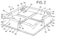
- the unitary packaging structure 10 is in the general form of a tray having a platform portion 18 which is adapted to support the shock sensitive article 12.
- the platform portion 18 has a peripheral portion 20 which is attached to a sidewall structure 22 forming part of the tray.
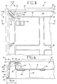
- the sidewall structure 22 forms an enclosure 24 which, in the preferred embodiment, when viewed from above or below, is in the shape of a polygon, such as the rectangle shape shown in Figure 3, or of an arcuate structure such as a circle, oval or ellipse.
- the sidewall structure 22, as may be seen most clearly in Figure 4, has a transverse bridge section 26 which has an inboard edge portion 28 and an outboard edge portion 30.
- the bridge section 26 may be a generally flat, horizontal member, as shown in Figures 1-7, but may also be provided in other shapes, such as the curved cross-section, as shown in Figure 10a or the pointed cross-section, as shown in Figure 10b.
- a relatively shorter, inboard wall 32 has a proximal end 34 which is integral with the inboard end portion 28 of the bridge section 26 and has a distal end 36 which extends in a direction away from the bridge section 26.
- the sidewall structure 22 also has a relatively longer wall 38 with a proximal end 40 which is integral with the outboard end portion 30 of the bridge section 26.
- the relatively longer outboard wall 38 has a distal or lower end 42 which extends in a direction away from the bridge section 26.
- the peripheral portion 20 of the platform portion 18 is integral with the distal end portion 36 of the shorter wall 32 such that the platform portion 18 of the platform portion 18 is supported by the sidewall structure 22.
- the platform portion 18 is held in suspended relationship above a lower end 42 of the longer wall 38 by the sidewall structure 22.
- the distance between the platform portion 18 and the lower edge of the lower end 42 will be referred to as the cushion thickness 58 (best seen in Figure 4).
- the base of the shock sensitive article 12 is in a relatively tight fit against the shorter wall 32 of the sidewall structure 22. Indeed, for better shock protection it is preferred that the shorter wall 32 is adapted to pressingly engage the article 12 when the article 12 is positioned on the platform portion 18 (best seen in Figure 6).
- the sidewall structure 22 can include a foot structure 46 which has an inner peripheral edge 48 and an outer peripheral edge 50.
- the foot structure 46 extends along the lower end 42 of the longer wall section 38.
- the outer edge 50 of the foot structure 46 extends outboard from the lower end 42 of the longer wall 38.
- the foot structure 46 will be made integrally with the lower end 42 of the longer wall 38. It is preferable that the foot structure 46 flare outwardly from the lower end 42 of the longer wall 38 at such an angle that when the foot structure 46 is positioned against a flat surface, for example, against the bottom 14a of the container 14, the outer edge 50 of the foot structure 46, which is in contact with the container walls 14b, 14c, will make an acute angle with the flat surface.
- At least one corner 52 is provided to the sidewall structure 22 when the structure is of polygonal shape as shown in the preferred embodiment in Figure 2, each corner defining a pair of wall segments from adjacent portions of the sidewall structure.
- the four corners 52 will define four wall segments, each segment including a portion of the shorter wall 32, a portion of the longer wall 38, and a portion of the bridge section 26.
- the structure is formed of a flexible, preferably polymeric, material to allow shocks to be dissipated primarily via flexing of the walls 32 and 38 which, after such flexing, elastically return to their original shape.
- a flexible, preferably polymeric, material to allow shocks to be dissipated primarily via flexing of the walls 32 and 38 which, after such flexing, elastically return to their original shape.
- An advantage of this property is that the present packaging structure 10 may absorb repeated shock impacts without deteriorating.
- Any of a number of polymeric materials can be utilized to form the unitary packaging structure 10. Generally, such materials will be characterized by the physical properties of durability, elasticity or "memory”, high and low temperature stability, and thermoformability.
- High density polyethylene generally has a stiffness of about 10.55 x 10 7 kg/cm 2 (150,000 psi). This provides sufficient flexibility for the purposes of the present invention and sufficient plasticity so that the packaging structure 10, will return to its original loaded or less stressed state following absorption of a shock. If desired, the HDPE used in making the packaging structure 10 may be recycled, post-consumer material.
- the sheets of polymeric material which are thermoformed into the packaging structure 10 will generally be from about 10 to about 90 gauge (mils) in thickness.
- the present packaging structure 10 may also be produced by injection molding. Regardless of the method of manufacture, the particular thickness of the polymeric material making up the sidewall structure 22 and the platform portion 18 will be a function of the specific properties of the polymeric material itself, and the weight and shape of the shock sensitive article 12 which is to be supported by the particular packaging structure 10.
- the packaging structure 10 of the present invention can be designed to provide sufficient protection for the packaged article 12 to provide protection as low as the 20g level under all ambient weather conditions.
- the downward force illustrated by the arrow 44 exerted upon the platform 18 is dissipated into a lateral force by the sidewall structure 22. More specifically, this force is taken up in flexure of the walls 32 and 38, and the bridge section 26. Ideally, the flexure of the sidewall structure 22 will permit the platform 18 to descend into the cushion distance 58 up to a maximum extent which is less than or equal to the lower end 42 of the longer wall 38. In the preferred embodiment, the platform 18 is designed to descend approximately 90% of the cushion distance under maximum shock load.
- the unitary packaging structure 10 is constructed as shown in Figures 1-7.
- a shock limiting device 54 is provided for absorbing the vertical compression experienced by the platform 18 when a vertical shock force is suffered.
- the shock limiting device 54 is configured as a V-shaped indentation which is formed in the sidewall structure 22, and is integral with the bridge 26, the shorter wall 32 and the longer wall 38.
- the indentation 54 extends from the bridge 26 into the shorter wall 32 and into the longer wall 38, and has end faces 56a, 56b.
- each indentation 54 defines the adjacent portions of the sidewall structure 22 into wall segments.
- the indentations 54 are configured and positioned on the sidewall structure 22 to compress upon the exertion of the generally vertically directed forces generated by shock impacts upon the container 14 which cause the platform portion 18 to move into the cushion distance 58.
- the horizontal distance 59 between the peripheral edge of the platform portion 18 and the outer peripheral edge 50 of the foot 46 is approximately equal to the cushion distance 58.
- the sidewall structure 22 is configured to accommodate an amount of lateral compression which is approximately equal to said cushion distance.
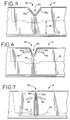
- the packaging structure 10 of the invention is shown in the unloaded position, with the platform portion 18 at its uppermost location, and each of the indentations 54 at their most splayed position. This is the configuration of the packaging structure 10 prior to the placement of the fragile article 12 therein.
- the packaging structure 10 is shown in the position after a fragile article 12 has been inserted for shipment. It will be evident that the platform portion 18 has become slightly lowered due to vertical loading, represented by the arrow 44, which also causes some peripheral compression as described above, and which is represented here as the arrows 60. In order to compensate for, and absorb this peripheral compression, and to prevent deformation of the corners 52, the indentation 54 closes slightly so that the end faces 56a, 56b are located closer together. An additional effect of the placement of the article 12 upon the packaging structure 10 is that the outboard wall 38 will bow outward slightly as shown at 38a and may even contact a wall of the container 14 (best seen in Figure 1). Thus, the overall height of the packaging structure 10 is reduced slightly.
- the packaging structure 10 is shown in the maximum shock absorbing position, which will occur upon the application of a shock force to the container 14 and the transmission of that force to the fragile article 12.
- the impact which is of the type occurring upon the dropping of the container 14, will cause sufficient g-forces to cause maximum vertical lowering of the platform portion 18 to virtually the full extent of the cushion distance 58.
- the end faces 56a, 56b will assume a contacting relationship with each other through the application of the compression forces 60.
- the bowing out of the outboard wall 38 is more extreme in this situation, as indicated by the line 38b (best seen in Figure 4).
- the line 38b will represent the direction of forces generated by the shock impact, these forces being transmitted to the container 14.
- the overall height of the packaging structure 10 will be reduced from the loaded condition depicted in Figure 6.
- FIG. 7 illustrates that as the platform portion 18 reaches the full limit of the cushion distance 58, the end faces 56a, 56b come into contact with each other. Through this closing of the end faces, the indentation 54 limits the compression forces 60 to reduce further vertical movement of the platform portion 18 towards the lower end 42 of the longer wall 38.
- a trough 62 or as illustrated a plurality of troughs 62, can be provided which are integrally formed into the platform portion 18 and which extend generally away from the bridge portion 26 of the sidewall structure 22.
- the trough or troughs 62 serve to provide structural support for the platform 18.
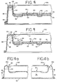
- an important feature of the packaging structure 10 of the present invention is that it can be made of a shape and size such that a plurality of the structures 10 can nest, one within the other.
- Three such structures, labeled 10b, 10c, 10d, are depicted.
- the shorter wall 34 and the longer wall 38 are drafted or slightly angled from the vertical away from each other and from the respective integral edges 28, 30 of the bridge section 26.
- a plurality of the packaging structures 10 of the nature shown in Figure 8 can nest, one within the other, and the total thickness of the resulting stack will simply be the total height of one of the packaging structures 10, plus the sum of thicknesses of the platform walls of additional packaging structures 10 which are nested with it, as well as a small vertical spacing distance 64 between platform 18 of adjacent pairs of structures 10.
- This stackability of the present packaging structure is a significant space-saving advantage over conventional foam packaging.
- the platform portion 18 may, at times, advantageously include a formation for releasably engaging and limiting horizontal or lateral movement of the shock sensitive article 12.
- the first releasable engaging formation can be in the nature of one or more recesses 66, each of which is adapted to hold a protruding support 68, for example a foot, which protrudes from the shock sensitive article 12 (best seen in Figure 1).
- the platform portion 18 it is not necessary that the platform portion 18 be generally planar as illustrated in the Figures.
- the platform portion 18 may be configured for a form-fitting relationship atop the shock sensitive article 12 as shown in Figure 1.
- the platform portion 18 of the upper structure 10a would generally not be planar, but would instead be shaped to properly complement or match the top portion of the shock sensitive article 12 and fit telescopingly therewith.
- the embodiment 210 basically includes at least two structures 10, labeled 10e and 10f, which are placed one atop the other in nesting relationship for accommodating a single shock sensitive article 12 (shown partially in phantom). As such, identical components have been designated with identical reference numerals. This arrangement is contemplated for use in the case of unusually heavy fragile articles 12.
- the structures 10 may also be fabricated of relatively thin gage or otherwise less expensive polymeric material to save costs. Further, two or more such structures 10 may be used to provide the same amount of strength as a single structure 10 fabricated of relatively thicker or more costly material.
- the structures 10 are nested properly, an air pocket forms in the area 72 between the nested structures, which provides an additional shock absorbing cushion.
- the upper and lower packaging structures 10 may be fused together by chemical adhesive, ultrasonic welding or other methods, to seal the air space 72.
- FIG. 10a another alternative embodiment of the packaging structure of the invention is generally designated 310.
- Components of the structure 310 which are identical to corresponding components of the structure 10 have been designated with identical reference numerals.
- the structure 310 differs from the structure 10 in that a web of material 74 is sealingly affixed to the lower end 42 of the wall 38, or to the foot 46.
- An air pocket 76 is thus created within the structure 310, which provides additional shock absorbing qualities. It will be appreciated however, that in this embodiment, any downward movement of the platform 18 into the cushion distance 58 is restricted by the air pocket 76. Further, the structure 310 would not be nestable, and would require greater storage space.
- the package 310 is contemplated for use with exceptionally heavy articles, and the above-identified disadvantages are outweighed by its greater shock absorbing capacity.
- the structure shown in Figure 10a also includes the alternative curved cross-sectional shape of the bridge 26a of the sidewall structure 22.
- Figure 10b depicts another embodiment of the packaging structure 310, which is designated 310a, and is identical to the packaging structure 310 except for the fact that the bridge formation 26b is pointed or wedge-shaped in cross-section. This embodiment may be employed when greater flexibility of the sidewall structure 22 is desired. It will be appreciated that the bridge portion 26 may alternatively be rounded as in 26a or pointed as in 26b.
- the package of the invention 10, 210, 310, 310a is placed in the bottom 14a of the carton 14, and the fragile article 12 is positioned within the enclosure 24.
- This initial loading will cause the platform 18 to depress slightly, as depicted in Figure 6.
- the sidewall structure 22 will compress around the periphery of the article 12, thus gripping it tightly in the region of the inboard bridge edge 28.
- the foot 46, and possibly a bowed portion of the longer wall 38 will press against the corresponding walls 14b, 14c of the container 14.
- additional structures 10, 10a, 210, or 310 may be placed around the sides of the article 12 between the article and the container wall.
- Such additional structures may be separate units as shown in Figure 1, or may be joined along adjacent edges 50 of the foot 46.
- the platform portion 18 will move downward, into the cushion distance 58, causing a longitudinal compression about the enclosure 24.
- the downward movement of the platform portion 18, and the compression of the sidewall structure 22, will be stopped once the adjacent faces 56a, 56b of the shock limiting indentations 54 come into contacting relationship with each other. This downward movement will preferably be within the maximum cushion distance 58.
- the package 10, 210, 310, 310a will resume its original loaded position, and will be capable of absorbing repeated shock impacts without suffering a deterioration of shock absorbing capacity.
- the present invention provides a unitary packaging structure 10, 210, 310, 310a which is useful for providing cushioning for a shock sensitive article 12.
- Advantages of the packaging structure 10, 210, 310, 310a of the present invention include that it can absorb repeated shocks of as much as 90% of its cushioning distance, that it can be made of material which is substantially 100% recyclable, it can be made inexpensively by mass production techniques, and a plurality of the packaging structures 10 can be readily stacked together in a small space for storage and/or shipment.
- a significant environmental advantage is provided utilizing such structures as opposed to the prior art rigid polystyrene foams.
Landscapes
- Engineering & Computer Science (AREA)
- Mechanical Engineering (AREA)
- Buffer Packaging (AREA)
- Wrappers (AREA)
- Polyoxymethylene Polymers And Polymers With Carbon-To-Carbon Bonds (AREA)
Claims (8)
- Einheitlichche Verpackungsstruktur (10) für einen stoßempfindlichen Artikel (12), enthaltend:einen Plattformabschnitt (18), der so ausgelegt ist, daß er mindestens einen Teil des Artikels (12) trägt und einen Umfangsabschnitt (20) hat; undeine Seitenwandstruktur (22) aus flexiblem Material, die eine Umrandung (24) um mindestens einen Teil des Plattformabschnitts (18) bildet, welche Seitenwandstruktur (22) eine Innenwand (32) einschließt, die mit dem Umfangsabschnitt (20) verbunden ist, und eine Außenwand (38), die durch einen Brückenabschnitt (26) in beabstandeter Beziehung von der Innenwand (32) gehalten wird, welche Innenwand (32) relativ kürzer ist als die Außenwand (38), so daß die Plattform (18) eine festgelegte Dämpfungsdistanz (58) über dem unteren Rand der Außenwand (38) gehalten wird, dadurch gekennzeichnet, daß die Struktur (10) ferner enthält:eine in der Seitenwandstruktur (22) gebildete Stoßbegrenzungseinrichtung (54) zum Beschränken der Bewegung des Plattformabschnitts (18) zu dem unteren Rand der Außenwand (38), wenn eine Stoßbelastung des Plattformabschnitts (18) auftritt, welche Stoßbegrenzungseinrichtung mindestens eine Vertiefung (54) in dem Brückenabschnitt (26) und der Innen- und Außenwand (32, 38) einschließt, wobei die bzw. jede Vertiefung (54) die Seitenwandstruktur (22) in mehrere Wandsegmente einteilt, die Stirnflächen (56a, 56b) haben, und bei der Stoßbelastung des Plattformabschnitts (18) die Stirnflächen von benachbarten Wandsegmenten so konfiguriert sind, daß sie miteinander in Kontakt kommen, um die Bewegung des Plattformabschnitts (18) zu begrenzen.
- Verpackungsstruktur (10) nach Anspruch 1, bei welcher die bzw. jede Vertiefung (54) allgemein V-förmig ist und von dem Brückenabschnitt (26) in die Innenwand (32) und die Außenwand (38) verläuft.
- Verpackungsstruktur (10) nach Anspruch 2, bei welcher die Stoßbegrenzungseinrichtung (54) die Bewegung des Plattformabschnitts (18) auf eine Distanz begrenzt, die kleiner oder gleich der Dämpfungsdistanz ist.
- Verpackungsstruktur (10) nach einem der vorstehenden Ansprüche, bei welcher die Innenwand (32) und die Außenwand (38) relativ zu dem Brückenabschnitt (26) schräg gestellt sind, um das Ineinandersetzen von mehreren Verpackungsstrukturen zu erleichtern.
- Verpackungsstruktur (310) nach einem der vorstehenden Ansprüche, bei welcher der Brückenabschnitt (26a) einen gerundeten Querschnitt hat.
- Verpackungsstruktur (310a) nach einem der Ansprüche 1-4, bei welcher der Brückenabschnitt (26b) einen spitzen Querschnitt hat.
- Verpackungsstruktur (310) nach einem der vorstehenden Ansprüche, enthaltend eine Materialbahn (74), die an einem unteren Rand der Seitenwandstruktur (22) befestigt ist, um eine Lufttasche zu bilden.
- Verpackungsstruktur (10) für stoßempfindliche Artikel (12) umfassend eine erste einheitliche Verpackungsstruktureinheit (10b) gemäß Anspruch 1, die in dichter, ineinandergesetzter Beziehung mit einer weiteren derartigen einheitlichen Verpackungsstruktur (10c) angeordnet ist.
Applications Claiming Priority (3)
| Application Number | Priority Date | Filing Date | Title |
|---|---|---|---|
| US840453 | 1992-02-24 | ||
| US07/840,453 US5226543A (en) | 1992-02-24 | 1992-02-24 | Packaging for fragile articles |
| PCT/US1993/001537 WO1993016939A1 (en) | 1992-02-24 | 1993-02-22 | Packaging for fragile articles |
Publications (3)
| Publication Number | Publication Date |
|---|---|
| EP0626923A1 EP0626923A1 (de) | 1994-12-07 |
| EP0626923A4 EP0626923A4 (en) | 1996-05-22 |
| EP0626923B1 true EP0626923B1 (de) | 1997-12-29 |
Family
ID=25282425
Family Applications (1)
| Application Number | Title | Priority Date | Filing Date |
|---|---|---|---|
| EP93906985A Expired - Lifetime EP0626923B1 (de) | 1992-02-24 | 1993-02-22 | Verpackung für zerbrechliche gegenstände |
Country Status (10)
| Country | Link |
|---|---|
| US (1) | US5226543A (de) |
| EP (1) | EP0626923B1 (de) |
| AT (1) | ATE161505T1 (de) |
| AU (1) | AU3775193A (de) |
| DE (1) | DE69315986T2 (de) |
| DK (1) | DK0626923T3 (de) |
| ES (1) | ES2111153T3 (de) |
| GR (1) | GR3025877T3 (de) |
| MX (1) | MX9301020A (de) |
| WO (1) | WO1993016939A1 (de) |
Families Citing this family (43)
| Publication number | Priority date | Publication date | Assignee | Title |
|---|---|---|---|---|
| WO1994006704A1 (en) * | 1992-09-24 | 1994-03-31 | Brødrene Hartmann A/S | Packaging element made from pulp material |
| US5439114A (en) * | 1993-08-11 | 1995-08-08 | Stone Container Corporation | Apparatus for supporting an article within a container |
| US5385232A (en) * | 1994-01-24 | 1995-01-31 | Plastofilm Industries Inc. | Packaging for fragile articles having controlled collapsibility |
| US5515976A (en) | 1995-08-18 | 1996-05-14 | Plastofilm Industries, Inc. | Packaging for fragile articles within container |
| US5799796A (en) * | 1996-04-02 | 1998-09-01 | Innovated Packaging Company, Inc. | Spring system end cap for packaging fragile articles within shipping cartons |
| US5765746A (en) * | 1996-06-18 | 1998-06-16 | Gateway 2000, Inc. | Restricted orientation shipping carton blank |
| US6010007A (en) * | 1997-02-21 | 2000-01-04 | Plastofilm Industries, Inc. | Thermoformed fragility packaging |
| USD414412S (en) | 1998-01-15 | 1999-09-28 | Tefal S.A. | Packaging for kitchen utensil |
| US5988393A (en) * | 1998-06-15 | 1999-11-23 | United Microelectronics Corp. | Storage box for semiconductor wafers |
| US5984101A (en) * | 1998-08-26 | 1999-11-16 | Carrier Corporation | Shipping protector |
| US6261653B1 (en) | 1999-04-06 | 2001-07-17 | Forrest Smith | Molded product cushioning device |
| US6123200A (en) * | 1999-04-06 | 2000-09-26 | Plastofilm Industries | Fragility packaging article with controlled resiliency |
| JP3398084B2 (ja) * | 1999-04-28 | 2003-04-21 | シャープ株式会社 | トナー貯蔵部を有するユニットの梱包装置および方法 |
| US6105765A (en) * | 1999-06-29 | 2000-08-22 | Chu; Cheng-Kang | Package case for electric appliances and computers |
| US6520337B2 (en) | 2000-01-24 | 2003-02-18 | Forrest Smith | Unitary product cushioning structure |
| CH691297A5 (it) * | 2000-03-09 | 2001-06-29 | Rentapack Sagl | Contenitore per imballaggio atto a venire riutilizzato. |
| USD454782S1 (en) | 2000-07-11 | 2002-03-26 | Hewlett-Packard Company | Container package for electronic devices |
| WO2002030787A1 (en) * | 2000-10-13 | 2002-04-18 | Seiko Epson Corporation | Cushion material for packaging and package |
| US20040011694A1 (en) * | 2002-07-17 | 2004-01-22 | Hann-Kuang Chen | Plate for placement of cooked and frozen shrimp |
| US6840381B2 (en) | 2002-07-31 | 2005-01-11 | Rsvp Operations, Llc | Packaging for fragile items |
| US7819279B2 (en) * | 2002-08-14 | 2010-10-26 | International Molded Packaging Corporation | Latchable container system |
| US7204388B2 (en) * | 2002-08-14 | 2007-04-17 | International Molded Packaging Corporation | Latchable container system |
| US6805241B2 (en) * | 2002-09-20 | 2004-10-19 | Forrest Smith | Protective packaging device having multiple deflection elements |
| US6786334B2 (en) * | 2002-09-20 | 2004-09-07 | Forrest Smith | Protective packaging structure for shock sensitive products and co-packaged accessories therefor |
| US20040098949A1 (en) * | 2002-11-21 | 2004-05-27 | Taiwan Semiconductor Manufacturing Co., Ltd | Packaging method for wafers |
| US7131617B2 (en) * | 2003-11-19 | 2006-11-07 | Rsvp Operations, Llc | Modified spring system end cap for packaging fragile articles within shipping cartons |
| US7299926B2 (en) * | 2004-08-10 | 2007-11-27 | Hewlett-Packard Development Company, L.P. | Packaging insert and method |
| US20060108255A1 (en) * | 2004-11-22 | 2006-05-25 | Cheng-Kang Chu | Manufacturing method of a packing cushion for electric equipments and a structure of the packing cushion |
| USD523338S1 (en) | 2005-09-13 | 2006-06-20 | Quantum Corporation | Shipping tray for multiple cartridges |
| TWI321543B (en) * | 2006-06-30 | 2010-03-11 | Qisda Corp | Packing system |
| JP4235840B2 (ja) * | 2006-09-19 | 2009-03-11 | 船井電機株式会社 | プラズマテレビジョンの梱包構造およびパネル型表示装置の梱包構造 |
| DE102007003529B3 (de) * | 2007-01-19 | 2008-09-04 | Söhner Kunststofftechnik GmbH Präzisionsthermoformen | Transport- und Schutzvorrichtung |
| DE102007038107A1 (de) * | 2007-08-01 | 2009-02-12 | Storopack Hans Reichenecker Gmbh | Verpackung |
| US20090038978A1 (en) * | 2007-08-09 | 2009-02-12 | Tzong Shen Lay | Environmental protection paper pulp packaging |
| GB0818508D0 (en) * | 2008-10-09 | 2008-11-19 | Protective Packaging Systems Ltd | Packaging |
| US9056708B2 (en) * | 2008-11-26 | 2015-06-16 | Forrest Smith | Product cushioning device for packaging shock sensitive products |
| JP5429660B2 (ja) * | 2009-03-26 | 2014-02-26 | ヤマト包装技術研究所株式会社 | 物品梱包ユニット |
| US8074952B2 (en) * | 2010-04-14 | 2011-12-13 | Sonoco Development, Inc. | Truncated pyramid shaped shipping base |
| DE102011051244B4 (de) * | 2011-06-22 | 2013-08-01 | Loewe Opta Gmbh | Verpackung für ein Flachdisplaygerät |
| US9738424B2 (en) * | 2014-07-11 | 2017-08-22 | Apple Inc. | Molded fiber packaging |
| CN114955246A (zh) * | 2021-02-25 | 2022-08-30 | 株式会社理光 | 冲击吸收体及包装体 |
| DE102024202629A1 (de) * | 2024-03-20 | 2025-09-25 | BSH Hausgeräte GmbH | Haushaltsgerät-Verpackung mit einer Bodenplatte und einer mit einer Sollbruchstelle versehenen Abdeckung für Aufnahmen für Füße eines Haushaltsgeräts, sowie Haushaltsgerätsystem |
| JP2026019398A (ja) * | 2024-07-26 | 2026-02-05 | セイコーエプソン株式会社 | 支持材、梱包品 |
Family Cites Families (23)
| Publication number | Priority date | Publication date | Assignee | Title |
|---|---|---|---|---|
| US2783930A (en) * | 1951-04-10 | 1957-03-05 | Baltimore Paper Box Company | Fiberboard end structures for shipping boxes |
| US2974788A (en) * | 1957-09-25 | 1961-03-14 | Keyes Fibre Co | Molded pulp packing for bottles |
| US2935206A (en) * | 1958-06-10 | 1960-05-03 | William H Smith | Holder for artist's supplies |
| US2994466A (en) * | 1960-06-15 | 1961-08-01 | Thompson Paul | Packaging box or tray |
| US3181766A (en) * | 1962-04-10 | 1965-05-04 | James T Kane | Cushioned package |
| US3176743A (en) * | 1962-05-07 | 1965-04-06 | Bundy Company | Container |
| US3437423A (en) * | 1965-04-01 | 1969-04-08 | Howmet Corp | Sterilizable instrument and appliance container |
| US3366231A (en) * | 1965-12-23 | 1968-01-30 | Singer Co | Inflatable packaging equipment |
| GB1224493A (en) * | 1968-03-22 | 1971-03-10 | Norman James Townsend | Packaging of articles |
| US3724654A (en) * | 1971-06-01 | 1973-04-03 | Sherwood Medical Ind Inc | Cup tray and container |
| CA952485A (en) * | 1971-06-07 | 1974-08-06 | Ferrero (P.) And C. S.P.A. | Display container |
| NL7311587A (nl) * | 1972-11-28 | 1975-02-25 | Degruyter B V | Verpakking, in het bijzonder voor chocolade letters. |
| US3835986A (en) * | 1973-01-30 | 1974-09-17 | Smith Corp A | Composite package |
| US4132311A (en) * | 1977-09-29 | 1979-01-02 | Shorewood Packaging Corp. | Tape cartridge/cassette receptacle |
| US4398212A (en) * | 1981-08-31 | 1983-08-09 | Vcs, Inc. | Shipping container for a closed circuit television system |
| US4645079A (en) * | 1984-10-09 | 1987-02-24 | Coulter Electronics,Inc. | Shipping and storing support |
| US4671407A (en) * | 1985-02-21 | 1987-06-09 | Amp Incorporated | Tray for card edge connectors |
| US4709808A (en) * | 1986-04-25 | 1987-12-01 | Owens-Illinois Plastic Products Inc. | Degradable polymer composition and articles prepared from same |
| US4823956A (en) * | 1986-08-13 | 1989-04-25 | Donaldson Company, Inc. | Composite container and its method of manufacture |
| US4883179A (en) * | 1988-01-06 | 1989-11-28 | Pierre Dionne | Angled packing material |
| DE3843990A1 (de) * | 1988-12-27 | 1990-07-05 | Thomson Brandt Gmbh | Verpackungspolster |
| GB2229416B (en) * | 1989-03-18 | 1992-11-04 | Spring Bathrooms Plc | Stackable pack |
| US4972951A (en) * | 1990-05-14 | 1990-11-27 | 501 U.S. Cosmo Plastics, Inc. | Tray for video tape |
-
1992
- 1992-02-24 US US07/840,453 patent/US5226543A/en not_active Expired - Lifetime
-
1993
- 1993-02-22 EP EP93906985A patent/EP0626923B1/de not_active Expired - Lifetime
- 1993-02-22 ES ES93906985T patent/ES2111153T3/es not_active Expired - Lifetime
- 1993-02-22 DK DK93906985.2T patent/DK0626923T3/da active
- 1993-02-22 WO PCT/US1993/001537 patent/WO1993016939A1/en not_active Ceased
- 1993-02-22 DE DE69315986T patent/DE69315986T2/de not_active Expired - Fee Related
- 1993-02-22 AT AT93906985T patent/ATE161505T1/de not_active IP Right Cessation
- 1993-02-22 AU AU37751/93A patent/AU3775193A/en not_active Abandoned
- 1993-02-24 MX MX9301020A patent/MX9301020A/es not_active IP Right Cessation
-
1998
- 1998-01-14 GR GR980400050T patent/GR3025877T3/el unknown
Also Published As
| Publication number | Publication date |
|---|---|
| MX9301020A (es) | 1994-03-31 |
| DE69315986D1 (de) | 1998-02-05 |
| EP0626923A4 (en) | 1996-05-22 |
| DE69315986T2 (de) | 1998-05-28 |
| US5226543A (en) | 1993-07-13 |
| DK0626923T3 (da) | 1998-02-09 |
| EP0626923A1 (de) | 1994-12-07 |
| WO1993016939A1 (en) | 1993-09-02 |
| ATE161505T1 (de) | 1998-01-15 |
| AU3775193A (en) | 1993-09-13 |
| GR3025877T3 (en) | 1998-04-30 |
| ES2111153T3 (es) | 1998-03-01 |
Similar Documents
| Publication | Publication Date | Title |
|---|---|---|
| US5226543A (en) | Packaging for fragile articles | |
| US5385232A (en) | Packaging for fragile articles having controlled collapsibility | |
| USRE37253E1 (en) | Packaging for fragile articles within container | |
| US6142304A (en) | Thermoformed fragility packaging | |
| US6123200A (en) | Fragility packaging article with controlled resiliency | |
| US7789239B2 (en) | Insert trays for packages, packages including such trays, and methods for packaging articles of manufacture | |
| US6820743B2 (en) | Shipping protector for bottles or the like | |
| US5738216A (en) | Adjustable and reusable protective packaging system | |
| US6840381B2 (en) | Packaging for fragile items | |
| US20040055928A1 (en) | Protective packaging structure for shock sensitive products and co-packaged accessories therefor | |
| CA2043680A1 (en) | Corner post and packaging system | |
| US4067442A (en) | Packaging glass bottles and other rigid containers | |
| US5799796A (en) | Spring system end cap for packaging fragile articles within shipping cartons | |
| JP2006273333A (ja) | 梱包用トレー | |
| US6769548B2 (en) | V-channel packing arrangements particularly for windshields | |
| US6805241B2 (en) | Protective packaging device having multiple deflection elements | |
| EP1718530B1 (de) | Modifizierte federsystem-endkappe zur verpackung von zerbrechlichen artikeln in versandkartons | |
| JP2002193341A (ja) | 薄型製品箱詰め用トレイ | |
| US20070125671A1 (en) | Surfboardpack | |
| GB2472434A (en) | Packaging material for protecting articles | |
| KR200391925Y1 (ko) | 포장용 완충재 | |
| CN223619164U (zh) | 一种具有抗压功能的包装箱 | |
| US20230356909A1 (en) | Retention packaging system | |
| JPH0754136Y2 (ja) | 包装体 | |
| JPH0314479A (ja) | 梱包容器 |
Legal Events
| Date | Code | Title | Description |
|---|---|---|---|
| PUAI | Public reference made under article 153(3) epc to a published international application that has entered the european phase |
Free format text: ORIGINAL CODE: 0009012 |
|
| 17P | Request for examination filed |
Effective date: 19940920 |
|
| AK | Designated contracting states |
Kind code of ref document: A1 Designated state(s): AT BE CH DE DK ES FR GB GR IE IT LI LU MC NL PT SE |
|
| A4 | Supplementary search report drawn up and despatched |
Effective date: 19960404 |
|
| AK | Designated contracting states |
Kind code of ref document: A4 Designated state(s): AT BE CH DE DK ES FR GB GR IE IT LI LU MC NL PT SE |
|
| RHK1 | Main classification (correction) |
Ipc: B65D 81/16 |
|
| 17Q | First examination report despatched |
Effective date: 19960723 |
|
| GRAG | Despatch of communication of intention to grant |
Free format text: ORIGINAL CODE: EPIDOS AGRA |
|
| GRAG | Despatch of communication of intention to grant |
Free format text: ORIGINAL CODE: EPIDOS AGRA |
|
| GRAH | Despatch of communication of intention to grant a patent |
Free format text: ORIGINAL CODE: EPIDOS IGRA |
|
| GRAH | Despatch of communication of intention to grant a patent |
Free format text: ORIGINAL CODE: EPIDOS IGRA |
|
| GRAA | (expected) grant |
Free format text: ORIGINAL CODE: 0009210 |
|
| AK | Designated contracting states |
Kind code of ref document: B1 Designated state(s): AT BE CH DE DK ES FR GB GR IE IT LI LU MC NL PT SE |
|
| REF | Corresponds to: |
Ref document number: 161505 Country of ref document: AT Date of ref document: 19980115 Kind code of ref document: T |
|
| REG | Reference to a national code |
Ref country code: CH Ref legal event code: NV Representative=s name: KELLER & PARTNER PATENTANWAELTE AG Ref country code: CH Ref legal event code: EP |
|
| REF | Corresponds to: |
Ref document number: 69315986 Country of ref document: DE Date of ref document: 19980205 |
|
| REG | Reference to a national code |
Ref country code: DK Ref legal event code: T3 |
|
| REG | Reference to a national code |
Ref country code: ES Ref legal event code: FG2A Ref document number: 2111153 Country of ref document: ES Kind code of ref document: T3 |
|
| ITF | It: translation for a ep patent filed | ||
| ET | Fr: translation filed | ||
| REG | Reference to a national code |
Ref country code: PT Ref legal event code: SC4A Free format text: AVAILABILITY OF NATIONAL TRANSLATION Effective date: 19971230 |
|
| REG | Reference to a national code |
Ref country code: IE Ref legal event code: FG4D Free format text: 78057 |
|
| PLBE | No opposition filed within time limit |
Free format text: ORIGINAL CODE: 0009261 |
|
| STAA | Information on the status of an ep patent application or granted ep patent |
Free format text: STATUS: NO OPPOSITION FILED WITHIN TIME LIMIT |
|
| 26N | No opposition filed | ||
| PGFP | Annual fee paid to national office [announced via postgrant information from national office to epo] |
Ref country code: SE Payment date: 19990127 Year of fee payment: 7 |
|
| PGFP | Annual fee paid to national office [announced via postgrant information from national office to epo] |
Ref country code: PT Payment date: 19990205 Year of fee payment: 7 |
|
| PGFP | Annual fee paid to national office [announced via postgrant information from national office to epo] |
Ref country code: IE Payment date: 19990208 Year of fee payment: 7 |
|
| PGFP | Annual fee paid to national office [announced via postgrant information from national office to epo] |
Ref country code: MC Payment date: 19990210 Year of fee payment: 7 |
|
| PGFP | Annual fee paid to national office [announced via postgrant information from national office to epo] |
Ref country code: GR Payment date: 19990212 Year of fee payment: 7 |
|
| PGFP | Annual fee paid to national office [announced via postgrant information from national office to epo] |
Ref country code: ES Payment date: 19990217 Year of fee payment: 7 |
|
| PGFP | Annual fee paid to national office [announced via postgrant information from national office to epo] |
Ref country code: DK Payment date: 19990225 Year of fee payment: 7 |
|
| PGFP | Annual fee paid to national office [announced via postgrant information from national office to epo] |
Ref country code: AT Payment date: 19990226 Year of fee payment: 7 |
|
| PGFP | Annual fee paid to national office [announced via postgrant information from national office to epo] |
Ref country code: NL Payment date: 19990228 Year of fee payment: 7 |
|
| PGFP | Annual fee paid to national office [announced via postgrant information from national office to epo] |
Ref country code: CH Payment date: 19990301 Year of fee payment: 7 |
|
| PGFP | Annual fee paid to national office [announced via postgrant information from national office to epo] |
Ref country code: BE Payment date: 19990325 Year of fee payment: 7 |
|
| PGFP | Annual fee paid to national office [announced via postgrant information from national office to epo] |
Ref country code: LU Payment date: 19990331 Year of fee payment: 7 |
|
| PG25 | Lapsed in a contracting state [announced via postgrant information from national office to epo] |
Ref country code: LU Free format text: LAPSE BECAUSE OF NON-PAYMENT OF DUE FEES Effective date: 20000222 Ref country code: IE Free format text: LAPSE BECAUSE OF NON-PAYMENT OF DUE FEES Effective date: 20000222 Ref country code: DK Free format text: LAPSE BECAUSE OF NON-PAYMENT OF DUE FEES Effective date: 20000222 Ref country code: AT Free format text: LAPSE BECAUSE OF NON-PAYMENT OF DUE FEES Effective date: 20000222 |
|
| PG25 | Lapsed in a contracting state [announced via postgrant information from national office to epo] |
Ref country code: SE Free format text: LAPSE BECAUSE OF NON-PAYMENT OF DUE FEES Effective date: 20000223 Ref country code: ES Free format text: LAPSE BECAUSE OF NON-PAYMENT OF DUE FEES Effective date: 20000223 |
|
| PGFP | Annual fee paid to national office [announced via postgrant information from national office to epo] |
Ref country code: FR Payment date: 20000225 Year of fee payment: 8 |
|
| PG25 | Lapsed in a contracting state [announced via postgrant information from national office to epo] |
Ref country code: BE Free format text: LAPSE BECAUSE OF NON-PAYMENT OF DUE FEES Effective date: 20000228 |
|
| PG25 | Lapsed in a contracting state [announced via postgrant information from national office to epo] |
Ref country code: MC Free format text: THE PATENT HAS BEEN ANNULLED BY A DECISION OF A NATIONAL AUTHORITY Effective date: 20000229 Ref country code: LI Free format text: LAPSE BECAUSE OF NON-PAYMENT OF DUE FEES Effective date: 20000229 Ref country code: GR Free format text: LAPSE BECAUSE OF NON-PAYMENT OF DUE FEES Effective date: 20000229 Ref country code: CH Free format text: LAPSE BECAUSE OF NON-PAYMENT OF DUE FEES Effective date: 20000229 |
|
| PGFP | Annual fee paid to national office [announced via postgrant information from national office to epo] |
Ref country code: DE Payment date: 20000426 Year of fee payment: 8 |
|
| BERE | Be: lapsed |
Owner name: ROBERTS STEPHENS VANAMBURG PACKAGING INC. Effective date: 20000228 Owner name: PLASTOFILM INDUSTRIES INC. Effective date: 20000228 |
|
| PG25 | Lapsed in a contracting state [announced via postgrant information from national office to epo] |
Ref country code: PT Free format text: LAPSE BECAUSE OF NON-PAYMENT OF DUE FEES Effective date: 20000831 |
|
| PG25 | Lapsed in a contracting state [announced via postgrant information from national office to epo] |
Ref country code: NL Free format text: LAPSE BECAUSE OF NON-PAYMENT OF DUE FEES Effective date: 20000901 |
|
| EUG | Se: european patent has lapsed |
Ref document number: 93906985.2 |
|
| REG | Reference to a national code |
Ref country code: CH Ref legal event code: PL |
|
| REG | Reference to a national code |
Ref country code: DK Ref legal event code: EBP |
|
| NLV4 | Nl: lapsed or anulled due to non-payment of the annual fee |
Effective date: 20000901 |
|
| REG | Reference to a national code |
Ref country code: IE Ref legal event code: MM4A |
|
| REG | Reference to a national code |
Ref country code: PT Ref legal event code: MM4A Free format text: LAPSE DUE TO NON-PAYMENT OF FEES Effective date: 20000831 |
|
| PG25 | Lapsed in a contracting state [announced via postgrant information from national office to epo] |
Ref country code: FR Free format text: LAPSE BECAUSE OF NON-PAYMENT OF DUE FEES Effective date: 20011031 |
|
| REG | Reference to a national code |
Ref country code: FR Ref legal event code: ST |
|
| PG25 | Lapsed in a contracting state [announced via postgrant information from national office to epo] |
Ref country code: DE Free format text: LAPSE BECAUSE OF NON-PAYMENT OF DUE FEES Effective date: 20011201 |
|
| REG | Reference to a national code |
Ref country code: ES Ref legal event code: FD2A Effective date: 20011010 |
|
| REG | Reference to a national code |
Ref country code: GB Ref legal event code: IF02 |
|
| PG25 | Lapsed in a contracting state [announced via postgrant information from national office to epo] |
Ref country code: IT Free format text: LAPSE BECAUSE OF NON-PAYMENT OF DUE FEES;WARNING: LAPSES OF ITALIAN PATENTS WITH EFFECTIVE DATE BEFORE 2007 MAY HAVE OCCURRED AT ANY TIME BEFORE 2007. THE CORRECT EFFECTIVE DATE MAY BE DIFFERENT FROM THE ONE RECORDED. Effective date: 20050222 |
|
| PGFP | Annual fee paid to national office [announced via postgrant information from national office to epo] |
Ref country code: GB Payment date: 20060109 Year of fee payment: 14 |
|
| GBPC | Gb: european patent ceased through non-payment of renewal fee |
Effective date: 20070222 |
|
| PG25 | Lapsed in a contracting state [announced via postgrant information from national office to epo] |
Ref country code: GB Free format text: LAPSE BECAUSE OF NON-PAYMENT OF DUE FEES Effective date: 20070222 |