EP0627248A2 - Aquarium de poissons jouets nageant ayant plusieurs poissons jouets et différentes positions d'aimants - Google Patents
Aquarium de poissons jouets nageant ayant plusieurs poissons jouets et différentes positions d'aimants Download PDFInfo
- Publication number
- EP0627248A2 EP0627248A2 EP94108478A EP94108478A EP0627248A2 EP 0627248 A2 EP0627248 A2 EP 0627248A2 EP 94108478 A EP94108478 A EP 94108478A EP 94108478 A EP94108478 A EP 94108478A EP 0627248 A2 EP0627248 A2 EP 0627248A2
- Authority
- EP
- European Patent Office
- Prior art keywords
- display device
- toy fish
- base
- magnetic field
- rotatable
- Prior art date
- Legal status (The legal status is an assumption and is not a legal conclusion. Google has not performed a legal analysis and makes no representation as to the accuracy of the status listed.)
- Granted
Links
Images




Classifications
-
- A—HUMAN NECESSITIES
- A63—SPORTS; GAMES; AMUSEMENTS
- A63H—TOYS, e.g. TOPS, DOLLS, HOOPS OR BUILDING BLOCKS
- A63H33/00—Other toys
- A63H33/26—Magnetic or electric toys
-
- A—HUMAN NECESSITIES
- A63—SPORTS; GAMES; AMUSEMENTS
- A63H—TOYS, e.g. TOPS, DOLLS, HOOPS OR BUILDING BLOCKS
- A63H23/00—Toy boats; Floating toys; Other aquatic toy devices
- A63H23/10—Other water toys, floating toys, or like buoyant toys
- A63H23/16—Aquatic toy installations; Harbour arrangements
Definitions
- This invention relates generally to a display apparatus for animated marine life and is particularly related to a display device comprising a liquid vessel and one or more marine lives swimming freely therein to simulate an aquarium. More particularly, the present invention relates to such aquarium containing one or more magnetically activated toy fish swimming freely in an aquatic habitat much in the same way as a natural fish swims in the sea. In one aspect, this invention relates to an aquarium containing one or more, magnetically activated swimming toy fish and a plurality of magnetic members disposed in said aquarium, which coact with the toy fish.
- Magnetically activated animated objects are well known in the art.
- a magnetically activated toy fish in a display device is described, for example, in United States Patent No. 3,239,956.
- This patent describes a marine life display apparatus in which an animated toy fish having a magnet therein is freely suspended in a liquid medium and is caused to move about therein in an effort to simulate the swimming movement of a natural fish.
- a power-driven magnetic means is disposed below the liquid medium in which the toy fish is freely suspended, and causes the fish to follow a continuous pattern of undulating movements through the liquid thus simulating the movements of a natural fish.
- Japanese Patent Application Kokai No. 55-101,383 (1980) and Japanese Patent Application Kokai No. 60-168,895 (1985) also disclose magnetically activated toy fish swimming in a liquid habitat.
- Most of the heretofore known toy fish include a magnetic means and the fish is freely suspended in a liquid medium disposed in a vessel supported on a base or a panel, and a magnetic means is disposed below the supporting base.
- the magnetic means below the supporting base is rotated by a power source thereby varying the magnetic field generated by the magnet and thus activating the toy fish.
- the movements of the toy fish is limited, usually to vertical and horizontal movements, and fail to simulate the movements of natural fish, in all directions, in a discontinuous pattern.
- the aquarium described therein comprises a housing and a transparent liquid vessel which is at least partially filled with a liquid, usually water, and in one embodiment, the liquid vessel has a convex front surface and a generally flat rear surface.
- a marine object such as a toy fish is freely suspended in the liquid, said toy fish having magnets therein and means for imparting buoyancy to the fish.
- One or more rotatable magnets disposed in said housing behind the rear surface of the liquid vessel rotate about a horizontal axis thus generating magnetic fields at different speeds.
- the magnetic toy fish and the rotating magnet or magnets co-act to cause the toy fish to move freely in all directions to simulate the swimming action of a natural fish in a liquid habitat.
- a background plate depicting different scenes such as a coral reef of a rock cave, can be disposed in the housing, behind the rear surface of said liquid vessel, to impart a more realistic and natural background scenery for the marine display.
- one toy fish is magnetically activated to swim about in the liquid. So far as it is known, there are no marine displays which contain, or which can accommodate a plurality of toy fish or marine lives, swimming in different directions, in one liquid-containing vessel.
- a marine display device containing a liquid medium and one or more marine toy objects, such as a fish, which are magnetically activated to swim freely in the liquid.
- a marine display device comprising a liquid vessel which may be in the general form of a liquid tank, a cup-shaped vessel or a prism.
- a plurality of toy marine objects e.g., toy fish, are freely suspended in, and swim freely in the liquid.
- Each toy fish contains an air chamber for imparting buoyancy to the toy fish, and comprises a magnetic member which co-act with the magnetic field produced in the liquid thereby causing the fish to swim in all directions.
- the display device of this invention also includes a plurality of magnetic field-creating devices such as magnetic plates, each plate being mounted on a rotatable shaft and being rotatable by said shaft.
- a means, such as a motor is connected to and causes rotation of the shafts, and the magnetic field-creating device, thus generating magnetic forces which act on the magnetic member in the toy fish and cause the toy fish to move about in omnidirectional manner within the liquid much as a natural fish swims in the sea.
- the magnetic field-creating devices are housed within chambers disposed within the liquid vessel in a manner which most efficiently produces magnetic forces through the liquid vessel.
- the marine display device comprises a water vessel or tank 2 containing a plurality of toy fish 1 swimming therein.
- the tank 2 has a base 4 and a magnetic field device 3.
- An air chamber 5 is provided in the fish 1 to impart buoyancy to the fish.
- a magnetic member 6 is disposed in the fish.
- the air chamber 5 may contain an air bag (not shown) in order to insure that the fish remain freely suspended in the liquid.
- Figure 1 which shows one embodiment of this invention, the bottom halves of the left and right sidewalls 2a, 2b in water tank 2 are semi-spherically curved on the inside, thereby forming holding cavities 7,8 for housing the rotating magnetic field devices 3.
- a magnetic plate 9 having north and south poles on its ends fits into and is supported by a supporting frame 10 which is formed of a non-magnetic material.
- Supporting shafts 11 provided at both ends of the support frame 10 are in turn supported by a machine housing (not shown).
- Rotation of the magnetic plate 9 is carried out as follows: As shown in Figure 1, a crown gear 12 is attached to the supporting shaft 11.
- the transmission mechanism 13 meshes with the gear 12 so that the rotation is transmitted from the rotating shaft 15 of the motor 14 to a pinion 16, and then to an intermediate shaft 17 via a large-diameter gear 18.
- Pinions 19, 19 attached at both ends of the intermediate shaft 17 each mesh with the crown gear 22 on a rotating shaft 21 attached to a pinion 20 at either end. In this way, rotation of the motor 14 is reduced and transmitted thus causing rotation of magnetic plates 9.
- the rotating magnetic field device 3 and the transmission mechanism 13 are situated on the base 4 of the tank.
- part of the bottom portion of the tank may be allowed to project into the water tank as shown by the dashed lines so as to form a guiding and inducing portion 23.
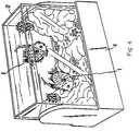
- the water tank 24 has simulated rock-shaped holding cavities 25,26 formed on the inside at the bottom half of left and right sidewalls 24a,24b.
- the rotating magnetic field devices 3 are housed in these holding cavities.
- these simulated rock-shaped holding cavities 25,26 can be formed by drawing simulated rock forms on a molded surface inside the water tank using paint, or by placing inside the tank a background member on which these simulated rocks have been drawn.
- a magnetic plate 9 having north and south poles on its ends fits into and is supported by a supporting frame 10 which is formed of a non-magnetic material.
- the supporting shafts 11 provided at both ends of the supporting frame 10 are in turn supported by a machine housing (not shown). These devices rotate the magnetic force generated from the magnetic plate 9 about the supporting shafts 11.
- Rotation of each magnetic plate 9 is carried out as follows.
- a crown gear 12 is attached to the supporting shaft 11 (Fig. 2).
- the transmission mechanism 13 that meshes with gear 12 is constructed so that the rotation is transmitted from the rotating shaft 15 of the motor 14 to a pinion 16, and then to an intermediate shaft 17 via a large-diameter gear 18.
- Pinions 19 attached at both ends of the intermediate shaft 17 mesh with a crown gear 22 on a rotating shaft 21 attached to a pinion 20 at either end. In this way, rotation of the motor 14 is reduced and transmitted thus causing rotation of magnetic plates 9.
- a simulated rock-shaped guiding and inducing portion 27 is formed so as to project out into the water tank, as shown by the solid line, in one part of the bottom portion 24c between the simulated rock-shaped holding cavities 25,26.
- corresponding supporting shafts 11 are supported in a freely rotatable manner, and a large-diameter gear 28 attached to this meshes with a pinion 19 attached midway on the intermediate shaft 17, and a magnetic plate 9 is supported on a supporting frame 10 attached to the supporting shafts 11.
- the holding cavities 7, 8, 25 and 26 are formed on the inside at the bottom half of left and right sidewalls 24a and 24b, but it is also possible to provide on the bottom surface 24c a holding cavity (not shown) that projects into the water tank in a box-like or conical shape, and to dispose a rotating magnetic field device 3 at the interior thereof.
- holding cavities 7, 8, 25 and 26 may also serve as guiding and inducing bodies that guide the swimming toys 1 at positions where the rising force of the rotating magnetic field devices 3 act.
- the embodiments described therein provide a plurality of holding cavities that project into the water tank 2 from the bottom half of the sidewalls, and disposed therein are the rotating magnetic field devices 3 that rotate about an axis of rotation which may be horizontal or somewhat inclined, and which is capable of imparting a rotating rising force to the fish.
- This construction causes the swimming toys that float or swimming toys that sink at a fixed speed to respond at a distance so as to swim into the rotating magnetic field, and also places a guiding and inducing body therebetween, which the swimming toys likewise swim and reach.
- the swimming toys are subjected primarily to an attractive rise or a repulsive rise due to the interaction between the magnet within the swimming toys and the rotating magnetic field. In this way the toy fish will swim freely much like a live fish, not only upward, horizontally, downward, and sideways from the left sidewall to the right sidewall, but also in forward and backward motions.
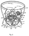
- a toy fish 101 swims freely in a generally cup-shaped water vessel or tank 102 which is supported by the base 103.
- the swimming fish 101 contains a chamber 104 which may house an airbag (not shown) for imparting buoyancy to the fish.
- a magnetic member 105 is also housed within the toy fish 101, with its magnetic poles oriented in the longitudinal axial direction of the fish.
- swimming fish toys having a given sinking speed are the most compatible with the omnidirectional upwardly-rotating magnetic field device 106 having only an upward force as described below.
- the present invention is not limited to this made alone.
- the water tank 102 is provided on its bottom surface with a conical holding projection 108 having a simulated rock form 107.
- a magnet chamber 109 is provided in the interior thereof.
- rotating shafts 110,111 and 112 are supported in the form of a regular polygon (as an equilateral triangle in this embodiment) along a transverse plane A-A that transects the holding projection 108 in an essentially horizontal manner, and magnetic plates 113,113,113 are supported on the respective rotating shafts 110,111 and 112 via supporting frames 114,114,114.
- a transmission mechanism 116 reduces rotation from the motor 115 and transfers the rotation to a large-diameter gear 117 attached to rotating shaft 110.
- a bevel gear 118 is attached at one end of the rotating shaft 110, and transfers rotation to rotating shaft 11 having attached at the corresponding end thereof another bevel gear 118 that meshes with the first bevel gear 118.
- rotation is also transferred to a rotating shaft 112 having attached at the corresponding end thereof another bevel gear 118 that meshes with the first bevel gear 118. If the number of teeth on each gear 118 is the same, the gears will all have the same rotation.
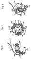
- FIGS 6 - 8 there are shown a transmission system for rotating shafts 110, 111 and 112 that supports the magnetic plates 113.
- a pulley 119 is attached to rotating shaft 110, and rotation from the motor 115 is transferred by a belt 120 to rotating shafts 111 and 112 by means of transfer wheels 121,121,121 that revolve about the periphery of supporting frames 114,114,114 for the respective rotating shafts 110,111 and 112, which are attached so as to be connected at the center of a regular polygonal shape in which each of the rotating shafts 110,111 and 112 is disposed.
- the traction springs 122,122,122 which bias the magnetic plates 113 and hold them in position.
- Figures 9 - 11 show another embodiment of a transmission system for rotating shafts 110,111 and 112 that support magnetic plates 113.
- Gears 125,125,125 which revolve on the periphery of the supporting frames 114,114,114 for the respective rotating shafts 110,111 and 112 are engaged directly with a worm gear 124 attached to the rotating shaft 123 of the motor 115.
- FIG. 5 - 11 permit the swimming toys within the water tank to swim in a free, varied, and natural manner due to the upwardly-rotating forces of the magnetic forces generated by the omnidirectional upwardly-rotating magnetic field device.
- FIG. 12 the swimming toy fish 201 swims freely in a liquid within the water tank 202 which is supported on a base 204.
- a pair of magnetic field devices 203 are disposed within the base 204 in the manner shown in this figure.
- the swimming toy fish 201 contains air chamber 205 and further comprises a magnetic member 206 which has a vertical action.
- the magnet within each fish is disposed so that both magnetic poles are oriented in the lengthwise direction.
- swimming toys having a given sinking speed are the most compatible with the rotating magnetic field device 203 which exert only an upward force.
- the invention is not limited to this arrangement.
- Water tank 202 is in the form of rectangular prism consisting of front and back sidewalls 222a,222b left and right sidewalls 222c,222d and a bottom panel 222e. The bottom of this water tank fits into a recessed mounting member 204a formed on the top surface of a base 204.
- the above-mentioned rotating magnetic field device 203 is designed so that magnetic plates 207 having north and south poles on the ends thereof are supported at given intervals on supporting frames 208 formed of a non-magnetic material, supporting shafts 209 provided on both end of these supporting frames 208 which are in turn supported on a machine frame 210, and the magnetic forces generated from the magnetic plates 207 about the axes of the supporting shafts 209 rotate upward toward the water tank 202.
- rotation of the magnetic plates 7 is achieved by a multiple-stage arrangement in which large-diameter gears 211 are attached to the supporting shafts 209, and the pinions 212 and large-diameter gears 213 that mesh with this successively mesh with a pair of intermediate gears 214.
- the last large-diameter gears 213 mesh with a pinion 217 on the rotating shaft 216 of the motor 215. In this way, the rotation of the motor 215 is reduced and transmitted to the supporting shafts 219.
- the magnetic forces of the mutually corresponding magnetic plates 217 rotate upward with respect to the water tank 202.
- Simulated rocks 218, water plants 219 and pebbles 220 are scattered about the interior of the water tank 202 (see Figure 16) in order to impart a more aesthetic appearance to the aquarium.
- These simulated rocks 18 and pebbles 20 may be "protrusion-molded" by a vacuum pack process, and then colored, although they may be made in other suitable manner.
- the magnetic plates are supported on rotating shafts which are, in turn, supported along the width on the outside of a water tank.
- the magnetic forces generated from the magnetic plates by rotation about the axes of the rotating shafts rotate upward within the water tank, as a result of which the upward rotating forces exerted by the magnetic forces generated by the magnetic plates cause the swimming toys to swim within the water tank.
- the interactions between the magnets built into the swimming toys and the rotating magnetic fields produce highly varied swimming motions.
- the rotating magnets 207 rotate in the same direction. However, if desired, these magnets may he made to rotate in opposite directions from one another by the addition of one more step down gears.
Landscapes
- Toys (AREA)
Applications Claiming Priority (6)
| Application Number | Priority Date | Filing Date | Title |
|---|---|---|---|
| JP35141/93 | 1993-06-02 | ||
| JP1993035141U JP2563993Y2 (ja) | 1993-06-02 | 1993-06-02 | 遊泳玩具装置 |
| JP15795493A JPH06343768A (ja) | 1993-06-02 | 1993-06-02 | 遊泳玩具装置 |
| JP157954/93 | 1993-06-02 | ||
| JP3514093U JP2551377Y2 (ja) | 1993-06-02 | 1993-06-02 | 遊泳玩具装置 |
| JP35140/93 | 1993-06-02 |
Publications (3)
| Publication Number | Publication Date |
|---|---|
| EP0627248A2 true EP0627248A2 (fr) | 1994-12-07 |
| EP0627248A3 EP0627248A3 (fr) | 1995-08-30 |
| EP0627248B1 EP0627248B1 (fr) | 1996-12-18 |
Family
ID=27288657
Family Applications (1)
| Application Number | Title | Priority Date | Filing Date |
|---|---|---|---|
| EP94108478A Expired - Lifetime EP0627248B1 (fr) | 1993-06-02 | 1994-06-01 | Aquarium de poissons jouets nageant ayant plusieurs poissons jouets et différentes positions d'aimants |
Country Status (3)
| Country | Link |
|---|---|
| EP (1) | EP0627248B1 (fr) |
| DE (1) | DE69401161T2 (fr) |
| DK (1) | DK0627248T3 (fr) |
Cited By (8)
| Publication number | Priority date | Publication date | Assignee | Title |
|---|---|---|---|---|
| RU2124379C1 (ru) * | 1997-12-01 | 1999-01-10 | Рощин Олег Алексеевич | Устройство для перемещения объектов, преимущественно игровых элементов игрушек |
| EP1008374A2 (fr) | 1998-12-11 | 2000-06-14 | DSLE System S.A. | Jouet magnétique animé |
| US6165036A (en) * | 1997-08-27 | 2000-12-26 | Kyosho Corporation | Water tank for wireless remote-controlled underwater toys |
| EP1157724A1 (fr) * | 2000-05-22 | 2001-11-28 | Takara Co., Ltd. | Système d'amusement pourvus d'objets nageants |
| RU2207180C1 (ru) * | 2002-04-19 | 2003-06-27 | Опарин Сергей Яковлевич | Способ создания упругой связи между двумя телами и магнитная игрушка |
| US6672250B1 (en) * | 2002-09-04 | 2004-01-06 | Thomas A. Traylor | Molded magnetic components for use in aquatic environments |
| US7297042B2 (en) * | 2003-11-11 | 2007-11-20 | Evolve Npd Limited | Magnetic toy |
| US9934613B2 (en) | 2014-04-29 | 2018-04-03 | The Florida International University Board Of Trustees | Systems for controlling a movable object |
Families Citing this family (1)
| Publication number | Priority date | Publication date | Assignee | Title |
|---|---|---|---|---|
| TWI422416B (zh) * | 2011-05-24 | 2014-01-11 | 國立暨南國際大學 | Waterborne mechanical organisms and their systems |
Family Cites Families (5)
| Publication number | Priority date | Publication date | Assignee | Title |
|---|---|---|---|---|
| DE1782654U (de) * | 1958-11-29 | 1959-02-05 | August-Wilhelm Hoewe | Spielzeugaquarium. |
| US3239956A (en) * | 1963-09-27 | 1966-03-15 | Jr Nicholas Canonica | Animated marine display |
| JPS60158884A (ja) * | 1984-01-30 | 1985-08-20 | 株式会社増田屋コ−ポレ−シヨン | 磁力線による玩具の作動装置 |
| GB2251807A (en) * | 1991-01-16 | 1992-07-22 | Chuang Chuan Tien | Magnetic fishing toy |
| JP2551373Y2 (ja) * | 1992-07-29 | 1997-10-22 | 株式会社増田屋コーポレーション | 遊泳玩具 |
-
1994
- 1994-06-01 DK DK94108478T patent/DK0627248T3/da active
- 1994-06-01 EP EP94108478A patent/EP0627248B1/fr not_active Expired - Lifetime
- 1994-06-01 DE DE1994601161 patent/DE69401161T2/de not_active Expired - Fee Related
Cited By (9)
| Publication number | Priority date | Publication date | Assignee | Title |
|---|---|---|---|---|
| US6165036A (en) * | 1997-08-27 | 2000-12-26 | Kyosho Corporation | Water tank for wireless remote-controlled underwater toys |
| RU2124379C1 (ru) * | 1997-12-01 | 1999-01-10 | Рощин Олег Алексеевич | Устройство для перемещения объектов, преимущественно игровых элементов игрушек |
| EP1008374A2 (fr) | 1998-12-11 | 2000-06-14 | DSLE System S.A. | Jouet magnétique animé |
| EP1157724A1 (fr) * | 2000-05-22 | 2001-11-28 | Takara Co., Ltd. | Système d'amusement pourvus d'objets nageants |
| US6564484B1 (en) | 2000-05-22 | 2003-05-20 | Takara Co., Ltd | Swimming element enjoying system |
| RU2207180C1 (ru) * | 2002-04-19 | 2003-06-27 | Опарин Сергей Яковлевич | Способ создания упругой связи между двумя телами и магнитная игрушка |
| US6672250B1 (en) * | 2002-09-04 | 2004-01-06 | Thomas A. Traylor | Molded magnetic components for use in aquatic environments |
| US7297042B2 (en) * | 2003-11-11 | 2007-11-20 | Evolve Npd Limited | Magnetic toy |
| US9934613B2 (en) | 2014-04-29 | 2018-04-03 | The Florida International University Board Of Trustees | Systems for controlling a movable object |
Also Published As
| Publication number | Publication date |
|---|---|
| DE69401161T2 (de) | 1997-05-15 |
| EP0627248B1 (fr) | 1996-12-18 |
| DE69401161D1 (de) | 1997-01-30 |
| EP0627248A3 (fr) | 1995-08-30 |
| DK0627248T3 (da) | 1997-05-12 |
Similar Documents
| Publication | Publication Date | Title |
|---|---|---|
| US5463826A (en) | Swimming toy fish aquarium having multiple toy fish and different magnet positions | |
| US5301444A (en) | Swimming toy fish | |
| US3239956A (en) | Animated marine display | |
| US5685096A (en) | Swimming toy fish aquarium having magnetic drive system for magnetically driving the toy fish in the aquarium | |
| EP0627248B1 (fr) | Aquarium de poissons jouets nageant ayant plusieurs poissons jouets et différentes positions d'aimants | |
| US8782934B2 (en) | Apparatus for housing artificial features and improved internal magnets for use in artificial features | |
| US6131318A (en) | Aquarium-used toy structure | |
| US5603994A (en) | Movable decoration assembly | |
| US3650056A (en) | Animated aquatic display | |
| EP0584944B1 (fr) | Poisson-jouet nageant | |
| US6263600B1 (en) | Display device | |
| AU728783B1 (en) | Swimming element enjoying system | |
| JPH06343768A (ja) | 遊泳玩具装置 | |
| JP3143881B2 (ja) | 複数尾の遊泳魚玩具 | |
| JP2563993Y2 (ja) | 遊泳玩具装置 | |
| JP2651778B2 (ja) | 複数尾の遊泳魚玩具 | |
| US2979861A (en) | Magnetic toy device | |
| US2298966A (en) | Kaleidoscope | |
| JP3042535U (ja) | 水槽玩具 | |
| JP2549243Y2 (ja) | 水槽玩具 | |
| JP2551377Y2 (ja) | 遊泳玩具装置 | |
| JP3019960U (ja) | 一般飼育観賞用水槽の遊泳玩具魚体駆動装置 | |
| JP3008343U (ja) | 水槽玩具 | |
| JP3073421U (ja) | 遊泳体鑑賞装置 | |
| JP3058228U (ja) | 水中装飾景観装置 |
Legal Events
| Date | Code | Title | Description |
|---|---|---|---|
| PUAI | Public reference made under article 153(3) epc to a published international application that has entered the european phase |
Free format text: ORIGINAL CODE: 0009012 |
|
| 17P | Request for examination filed |
Effective date: 19940601 |
|
| AK | Designated contracting states |
Kind code of ref document: A2 Designated state(s): BE DE DK FR GB IT NL SE |
|
| PUAL | Search report despatched |
Free format text: ORIGINAL CODE: 0009013 |
|
| AK | Designated contracting states |
Kind code of ref document: A3 Designated state(s): BE DE DK FR GB IT NL SE |
|
| 17Q | First examination report despatched |
Effective date: 19951023 |
|
| GRAG | Despatch of communication of intention to grant |
Free format text: ORIGINAL CODE: EPIDOS AGRA |
|
| GRAH | Despatch of communication of intention to grant a patent |
Free format text: ORIGINAL CODE: EPIDOS IGRA |
|
| GRAH | Despatch of communication of intention to grant a patent |
Free format text: ORIGINAL CODE: EPIDOS IGRA |
|
| GRAA | (expected) grant |
Free format text: ORIGINAL CODE: 0009210 |
|
| AK | Designated contracting states |
Kind code of ref document: B1 Designated state(s): BE DE DK FR GB IT NL SE |
|
| REF | Corresponds to: |
Ref document number: 69401161 Country of ref document: DE Date of ref document: 19970130 |
|
| ITF | It: translation for a ep patent filed | ||
| ET | Fr: translation filed | ||
| REG | Reference to a national code |
Ref country code: DK Ref legal event code: T3 |
|
| PLBE | No opposition filed within time limit |
Free format text: ORIGINAL CODE: 0009261 |
|
| STAA | Information on the status of an ep patent application or granted ep patent |
Free format text: STATUS: NO OPPOSITION FILED WITHIN TIME LIMIT |
|
| 26N | No opposition filed | ||
| REG | Reference to a national code |
Ref country code: GB Ref legal event code: IF02 |
|
| PGFP | Annual fee paid to national office [announced via postgrant information from national office to epo] |
Ref country code: GB Payment date: 20020508 Year of fee payment: 9 |
|
| PGFP | Annual fee paid to national office [announced via postgrant information from national office to epo] |
Ref country code: NL Payment date: 20020617 Year of fee payment: 9 Ref country code: FR Payment date: 20020617 Year of fee payment: 9 |
|
| PGFP | Annual fee paid to national office [announced via postgrant information from national office to epo] |
Ref country code: BE Payment date: 20020620 Year of fee payment: 9 Ref country code: DK Payment date: 20020620 Year of fee payment: 9 |
|
| PGFP | Annual fee paid to national office [announced via postgrant information from national office to epo] |
Ref country code: SE Payment date: 20020624 Year of fee payment: 9 |
|
| PGFP | Annual fee paid to national office [announced via postgrant information from national office to epo] |
Ref country code: DE Payment date: 20020814 Year of fee payment: 9 |
|
| PG25 | Lapsed in a contracting state [announced via postgrant information from national office to epo] |
Ref country code: GB Free format text: LAPSE BECAUSE OF NON-PAYMENT OF DUE FEES Effective date: 20030601 |
|
| PG25 | Lapsed in a contracting state [announced via postgrant information from national office to epo] |
Ref country code: SE Free format text: LAPSE BECAUSE OF NON-PAYMENT OF DUE FEES Effective date: 20030602 |
|
| PG25 | Lapsed in a contracting state [announced via postgrant information from national office to epo] |
Ref country code: DK Free format text: LAPSE BECAUSE OF NON-PAYMENT OF DUE FEES Effective date: 20030630 Ref country code: BE Free format text: LAPSE BECAUSE OF NON-PAYMENT OF DUE FEES Effective date: 20030630 |
|
| BERE | Be: lapsed |
Owner name: *HORIUCHI SHIGEYUKI Effective date: 20030630 |
|
| PG25 | Lapsed in a contracting state [announced via postgrant information from national office to epo] |
Ref country code: NL Free format text: LAPSE BECAUSE OF NON-PAYMENT OF DUE FEES Effective date: 20040101 Ref country code: DE Free format text: LAPSE BECAUSE OF NON-PAYMENT OF DUE FEES Effective date: 20040101 |
|
| GBPC | Gb: european patent ceased through non-payment of renewal fee |
Effective date: 20030601 |
|
| EUG | Se: european patent has lapsed | ||
| REG | Reference to a national code |
Ref country code: DK Ref legal event code: EBP |
|
| PG25 | Lapsed in a contracting state [announced via postgrant information from national office to epo] |
Ref country code: FR Free format text: LAPSE BECAUSE OF NON-PAYMENT OF DUE FEES Effective date: 20040227 |
|
| NLV4 | Nl: lapsed or anulled due to non-payment of the annual fee |
Effective date: 20040101 |
|
| REG | Reference to a national code |
Ref country code: FR Ref legal event code: ST |
|
| PG25 | Lapsed in a contracting state [announced via postgrant information from national office to epo] |
Ref country code: IT Free format text: LAPSE BECAUSE OF NON-PAYMENT OF DUE FEES;WARNING: LAPSES OF ITALIAN PATENTS WITH EFFECTIVE DATE BEFORE 2007 MAY HAVE OCCURRED AT ANY TIME BEFORE 2007. THE CORRECT EFFECTIVE DATE MAY BE DIFFERENT FROM THE ONE RECORDED. Effective date: 20050601 |