EP0627253A1 - Denitrierungssystem - Google Patents
Denitrierungssystem Download PDFInfo
- Publication number
- EP0627253A1 EP0627253A1 EP94108243A EP94108243A EP0627253A1 EP 0627253 A1 EP0627253 A1 EP 0627253A1 EP 94108243 A EP94108243 A EP 94108243A EP 94108243 A EP94108243 A EP 94108243A EP 0627253 A1 EP0627253 A1 EP 0627253A1
- Authority
- EP
- European Patent Office
- Prior art keywords
- oxidation
- denitrification
- inlet
- denitrification system
- humidity
- Prior art date
- Legal status (The legal status is an assumption and is not a legal conclusion. Google has not performed a legal analysis and makes no representation as to the accuracy of the status listed.)
- Granted
Links
Images




Classifications
-
- E—FIXED CONSTRUCTIONS
- E21—EARTH OR ROCK DRILLING; MINING
- E21F—SAFETY DEVICES, TRANSPORT, FILLING-UP, RESCUE, VENTILATION, OR DRAINING IN OR OF MINES OR TUNNELS
- E21F1/00—Ventilation of mines or tunnels; Distribution of ventilating currents
- E21F1/003—Ventilation of traffic tunnels
-
- B—PERFORMING OPERATIONS; TRANSPORTING
- B01—PHYSICAL OR CHEMICAL PROCESSES OR APPARATUS IN GENERAL
- B01D—SEPARATION
- B01D53/00—Separation of gases or vapours; Recovering vapours of volatile solvents from gases; Chemical or biological purification of waste gases, e.g. engine exhaust gases, smoke, fumes, flue gases, aerosols
- B01D53/34—Chemical or biological purification of waste gases
- B01D53/46—Removing components of defined structure
- B01D53/54—Nitrogen compounds
- B01D53/56—Nitrogen oxides
-
- F—MECHANICAL ENGINEERING; LIGHTING; HEATING; WEAPONS; BLASTING
- F24—HEATING; RANGES; VENTILATING
- F24F—AIR-CONDITIONING; AIR-HUMIDIFICATION; VENTILATION; USE OF AIR CURRENTS FOR SCREENING
- F24F8/00—Treatment, e.g. purification, of air supplied to human living or working spaces otherwise than by heating, cooling, humidifying or drying
- F24F8/10—Treatment, e.g. purification, of air supplied to human living or working spaces otherwise than by heating, cooling, humidifying or drying by separation, e.g. by filtering
- F24F8/15—Treatment, e.g. purification, of air supplied to human living or working spaces otherwise than by heating, cooling, humidifying or drying by separation, e.g. by filtering by chemical means
-
- F—MECHANICAL ENGINEERING; LIGHTING; HEATING; WEAPONS; BLASTING
- F24—HEATING; RANGES; VENTILATING
- F24F—AIR-CONDITIONING; AIR-HUMIDIFICATION; VENTILATION; USE OF AIR CURRENTS FOR SCREENING
- F24F8/00—Treatment, e.g. purification, of air supplied to human living or working spaces otherwise than by heating, cooling, humidifying or drying
- F24F8/10—Treatment, e.g. purification, of air supplied to human living or working spaces otherwise than by heating, cooling, humidifying or drying by separation, e.g. by filtering
- F24F8/15—Treatment, e.g. purification, of air supplied to human living or working spaces otherwise than by heating, cooling, humidifying or drying by separation, e.g. by filtering by chemical means
- F24F8/167—Treatment, e.g. purification, of air supplied to human living or working spaces otherwise than by heating, cooling, humidifying or drying by separation, e.g. by filtering by chemical means using catalytic reactions
-
- F—MECHANICAL ENGINEERING; LIGHTING; HEATING; WEAPONS; BLASTING
- F24—HEATING; RANGES; VENTILATING
- F24F—AIR-CONDITIONING; AIR-HUMIDIFICATION; VENTILATION; USE OF AIR CURRENTS FOR SCREENING
- F24F8/00—Treatment, e.g. purification, of air supplied to human living or working spaces otherwise than by heating, cooling, humidifying or drying
- F24F8/20—Treatment, e.g. purification, of air supplied to human living or working spaces otherwise than by heating, cooling, humidifying or drying by sterilisation
- F24F8/24—Treatment, e.g. purification, of air supplied to human living or working spaces otherwise than by heating, cooling, humidifying or drying by sterilisation using sterilising media
- F24F8/26—Treatment, e.g. purification, of air supplied to human living or working spaces otherwise than by heating, cooling, humidifying or drying by sterilisation using sterilising media using ozone
-
- F—MECHANICAL ENGINEERING; LIGHTING; HEATING; WEAPONS; BLASTING
- F24—HEATING; RANGES; VENTILATING
- F24F—AIR-CONDITIONING; AIR-HUMIDIFICATION; VENTILATION; USE OF AIR CURRENTS FOR SCREENING
- F24F8/00—Treatment, e.g. purification, of air supplied to human living or working spaces otherwise than by heating, cooling, humidifying or drying
- F24F8/40—Treatment, e.g. purification, of air supplied to human living or working spaces otherwise than by heating, cooling, humidifying or drying by ozonisation
-
- Y—GENERAL TAGGING OF NEW TECHNOLOGICAL DEVELOPMENTS; GENERAL TAGGING OF CROSS-SECTIONAL TECHNOLOGIES SPANNING OVER SEVERAL SECTIONS OF THE IPC; TECHNICAL SUBJECTS COVERED BY FORMER USPC CROSS-REFERENCE ART COLLECTIONS [XRACs] AND DIGESTS
- Y02—TECHNOLOGIES OR APPLICATIONS FOR MITIGATION OR ADAPTATION AGAINST CLIMATE CHANGE
- Y02A—TECHNOLOGIES FOR ADAPTATION TO CLIMATE CHANGE
- Y02A50/00—TECHNOLOGIES FOR ADAPTATION TO CLIMATE CHANGE in human health protection, e.g. against extreme weather
- Y02A50/20—Air quality improvement or preservation, e.g. vehicle emission control or emission reduction by using catalytic converters
Definitions
- the present invention relates to a denitrification system for processing exhaust gas of normal-temperature and low-concentration in automobile road tunnels or the like closed space.
- a conventional denitrification system of such type is generally configured as shown in Figs.11 and 15. The configuration will be explained with reference to the drawings.
- the NO x contained in the tunnel exhaust gas drawn by a fan 103 includes NO and NO2 as main components, of which NO is oxidized into NO2 by a high-voltage discharge ionizer 101, as shown in FIG.11.
- the NO2 obtained by oxidation and the NO2 originally existing in the NO x are absorbed by an NO2 absorbent filter 102 containing activated carbon and alkali,
- the tunnel exhaust gas 104 drawn by the fan 103 contains such components as SO2, soot and dust in addition to the nitrogen oxides (NO and NO2) as main components.
- NO and NO2 nitrogen oxides
- all the NO is oxidized into NO2 by an oxidizer 105, and NO2 is absorbed by an absorbent such as KNO2, KNO3, Ca(NO2)2 and Ca(NO3)2 in an absorbent filter 102, as seen from chemical formula 2.
- an absorbent such as KNO2, KNO3, Ca(NO2)2 and Ca(NO3)2 in an absorbent filter 102, as seen from chemical formula 2.
- a configuration for oxidation control is shown in the block diagram of FIG.16.
- the total NO amount 118 at the inlet is calculated from the NO concentration value 116 at the inlet obtained from an NO concentration meter 113 installed as a detection part at or near the inlet of the denitrification system, and from gas flow rate 117 calculated by an anemometer 114.
- a total inlet SO2 amount 124, a total inlet dust amount 126 and a total inlet humidity 128 are calculated from the output of an inlet SO2 concentration meter 120, an inlet dust concentration meter 121 and an inlet humidity meter 122, installed at detection part at or near the inlet of the denitrification system.
- the total inlet NO amount 118, the total inlet SO2 amount 124, the total inlet dust amount 126 and the total inlet humidity 128 are used to calculate and determine the oxidation amount 119 satisfying the formulae (1) and (2) described above.
- An open-loop control is employed in which the oxidation amount 119 is applied to the ionizer 101 as a control output. Whether the oxidation control is functioning properly or not is monitored by a residual NO concentration meter 129 and a post-oxidation residual O3 concentration meter 130 at a point subsequent to the oxidation process shown in FIG.15.
- This conventional denitrification system is what is called the laboratory test system which displays its denitrification performance only by the use of prepared sample gas. When the actual tunnel exhaust gas is used, therefore, such a system cannot maintain a high denitrification rate.
- the problems to encounter when the tunnel exhaust is used with the conventional denitrification system are:
- the primary object of the invention is to solve the above-mentioned problems and provide a denitrification system wherein (i) the dust which otherwise would reduce the denitrification rate is preliminarily removed, (ii) the oxidizing ability is controlled stably even when the NO concentration of the exhaust gas to be processed changes, and (iii) the system is superior in the oxidation power efficiency.
- a denitrification system which, in addition to the primary object of the denitrification system described above, does not lose in the NO2 purification ability of the NO2 absorbent filter even when the humidity of the exhaust gas at the inlet of the denitrification system decreases.
- a denitrification condition wherein optimum oxidizing condition for 100% oxidation from NO to NO2 was achieved by disrupting the equilibrium between NO and NO2 required for maintaining a high denitrification rate.
- optimum oxidizing conditions can be realized without supplying an excessive oxidizing material under the environmental conditions of humidity, dust and SO2 existing as interfering gases constantly changing in concentration.
- the denitrification system has an improved response characteristics with sharp changes of concentration at the inlet of the denitrification system.
- the denitrification system in accordance with the present invention comprises an electrostatic precipitator (hereinafter referred to as E.P.) installed in the foremost stage of the inlet of the denitrification system, an ozonizer for generating ozone required for oxidizing NO into NO2, an ozone supply nozzle installed in the stage immediately subsequent to the E.P., an agitator (the word agitator is used to include a fan) installed in the stage immediately subsequent to the ozone supply nozzle, and an NO2 absorbent filter installed in the stage immediately subsequent to the fan or the agitator.
- E.P. electrostatic precipitator
- ozonizer for generating ozone required for oxidizing NO into NO2
- an ozone supply nozzle installed in the stage immediately subsequent to the E.P.
- an agitator the word agitator is used to include a fan
- an NO2 absorbent filter installed in the stage immediately subsequent to the fan or the agitator.
- the denitrification system described above may further comprise a humidifier interposed between the ozone supply nozzle and the NO2 absorbent filter, a humidity sensor installed in the stage subsequent to the humidifier, and a humidity controller.
- the denitrification system described above may include an ozonizer for oxidizing the NO in the tunnel exhaust gas into NO2, a fan for drawing the tunnel exhaust gas, and an NO2 absorbent filter for absorbing the NO2 obtained by oxidation, whereby the oxidation is controlled by feeding back the residual O3 concentration after oxidation.
- the denitrification system according to the present invention may further include feedforward control means having the function of predicting amount of change of oxidation.
- the E.P. installed in the foremost stage of the inlet of the denitrification system removes the soot and dust, thereby preventing the reduction of denitrification rate which otherwise might be caused by the soot and dust attaching to the NO2 absorbent filter.
- the E.P. can perform a discharge oxidation function which provides a base for oxidising NO into NO2 on top of the function of dust collection.
- an ozonizer may be preferably installed for NO oxidation.
- the ozone generated by the ozonizer is mixed with the tunnel exhaust through the ozone supply nozzle.
- the ozone supply nozzle is installed in the stage immediately subsequent to the E.P. before the fan or the agitator, whereby the ozone issued from the ozone supply nozzle is prevented from being deoxidized to oxygen by the high-concentration dust.
- the issued ozone can be fully mixed with the exhaust by the agitating operation of the fan blade or the agitator. In other words, since the oxidation from NO to NO2 by ozone can be certainly performed, the NO2 obtained by oxidation can be absorbed by the NO2 absorbent filter.
- a feedback control is effected so that the humidifier performs the optimal humidification.
- this humidifier is installed in the stage before the ozone supply nozzle, ozone is supplied to the exhaust whose humidity has been increased by the humidifier.
- the humidifier therefore must be installed in the stage subsequent to the ozone supply nozzle on the one hand, and for the purpose of humidification, it must be in the pre-stage of the NO2 absorbent filter on the other hand.
- the most effective humidification is achieved by installing the humidifier between the ozone supply nozzle and the subsequent NO2 absorption filter.
- the denitrification system is configured to monitor the residual O3 after oxidation process always without being influenced by the total NO amount, total SO2 amount, total dust amount or humidity at the inlet of the system.
- the residual O3 concentration after oxidation is controlled by feedback oxidation in such a way when the residual ozone concentration is lower than a specified region, the oxidation amount of the ozonizer is increased, and vice versa, thereby to achieve a high denitrification rate.
- this system can be configured as described below, (i) The change ⁇ NO of varied NO amount during ⁇ t seconds is added to the real-time present value of total NO amount without being influenced by sharp changes in the total NO amount, total SO2 amount, total dust amount and or humidity at the inlet of the denitrification system, (ii) a base oxidation amount is calculated from the value NO + ⁇ NO (i.e., the total NO amount plus a predicted amount of change), and (iii) the base oxidation amount is corrected by the residual O3 concentration after oxidation, thereby to control the oxidation amount of the ozonizer. That is, the oxidation is controlled mainly with the feedforward control and auxiliarily with the feedback corrective control. Thus, a high denitrification rate is achieved.
- the E.P. in accordance with the invention removes dust which interferes with the oxidation, and an ozonizer easily controls amount of supplied ozone required for oxidizing the NO into NO2 through the ozone supply nozzle.
- a humidifier is added to a denitrification system, even when the exhaust gas humidity undergoes a change at the inlet of the denitrification system, the humidity is controlled so that the humidity at the inlet of the NO2 absorbent filter is within a predetermined region.
- a denitrification system provided in accordance with the present invention stably achieves a high denitrification rate.
- the invention provides a method of controlling the denitrification system comprising an oxidizer for oxidizing the NO in tunnel exhaust gas into NO2, a fan for drawing the tunnel exhaust gas, and an NO2 absorbent filter for absorbing the NO2 obtained by oxidation. And therein the oxidation is controlled by feeding back with the residual O3 concentration after oxidation, thereby providing a denitrification system with a high denitrification rate.
- means for controlling the denitrification system further comprises feedforward control means capable of tracking the oxidation stably and having the function of predicting the varied amount of the oxidation even when total NO amount, total SO2 amount, total dust amount or humidity undergoes a sudden change at inlet of the denitrification system.
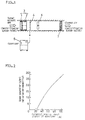
- FIG.1 is a general sectional side view showing a system configuration of a denitrification system in accordance with a first embodiment of the invention.
- FIG.2 is a graph showing an oxidation capability characteristic of an ozonizer.
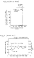
- FIG.3 is a graph showing a relation between the inlet NO concentration and denitrification rate.
- FIG.4 is a graph showing electric power efficiency characteristic for oxidation.
- FIG.5 is a sectional side view showing a system configuration of a denitrification system in accordance with a second embodiment of the invention.
- FIG.6 is a graph showing the relation between humidity and denitrification rate.
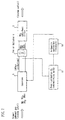
- FIG.7 is a block diagram showing a system configuration of a denitrification system in accordance with a third embodiment of the invention.
- FIG.8 is a block diagram for control operation flow of the third embodiment.
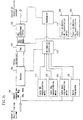
- FIG.9 shows a system configuration of a denitrification system according to a fourth embodiment of the invention.
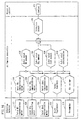
- FIG.10 is a block diagram for control operation flow of the fourth embodiment.
- FIG.11 is the general sectional side view showing the system configuration of a first conventional denitrification system.
- FIG.12 is the graph showing the relation between humidity and denitrification rate of the first conventional denitrification system.
- FIG.13 is the graph showing the characteristic of a general high-voltage discharge oxidation capability of ionizer.
- FIG.14 is the graph showing he relation between inlet NO concentration and denitrification rate.
- FIG.15 is the schematic side view with related circuit blocks of the system configuration of a second conventional denitrification system.
- FIG.16 is the block diagram showing control operation flow of the same conventional system.
- a denitrification system in accordance with this invention comprises an E.P. 3 installed in the foremost stage at the inlet of the denitrification system, an ozonizer 5 for generating ozone required for oxidizing NO into NO2, an ozone supply nozzle 4 installed in the stage immediately subsequent to the E.P. 3, a fan or an agitator 6 installed in the stage immediately subsequent to the ozone supply nozzle 4, and an NO2 absorbent filter 7 including activated carbon and at least one of the alkali materials such as NaOH, KOH, Ca(OH)2 and Ba(OH)2.
- the E.P. 3 located at the foremost stage of the inlet of the denitrification system removes the dust and therefore prevents the reduction in denitrification rate, which otherwise might be caused by the dust attaching to the NO2 absorbent filter 7. Further, the electric field intensity of the ionizer 1 in the E.P. 3 is increased to a strong field of 8.5 kV/cm, i.e., or about one and half times the electric field strength for the prior art And the voltage applied to the ioniser 1 is of negative voltage which has more oxidation effect than the positive voltage application. At the same time, the voltage applied to the collector 2 in E.P. 3 is made negative voltage application.
- the E.P. 3 has a function of discharge oxidation for making up a base for oxidizing a part of NO besides collection of the dust. (It is necessary, however, that the voltage applied to the ioniser 1 must be constant in order to secure stability of discharge oxidation.)
- an ozonizer 5 is provided in the apparatus.
- This ozonizer 5 supplies the ozone in an amount required for oxidizing NO remaining in the exhaust gas into NO2 through the ozone supply nozzle 4 by adjusting the amount by analog variable control.
- FIG.13 shows the oxidation capability characteristic of a conventional high-voltage discharge ionizer; and
- FIG.2 shows the oxidation capability characteristic of the ozonizer 5 in accordance with the embodiment under consideration.
- the ozonizer oxidation control according to the embodiment is much easier than the high-voltage discharge oxidation control in accordance with the prior art is clearly understood, by comparing the rise of the high-voltage discharge oxidation capability characteristic shown in FIG.13 with the rise of the ozonizer oxidation capability characteristic shown in FIG.2, which is a characteristic graph of one example of ozonizer. Also, since the electric power efficiency for oxidation can be improved over the conventional high-voltage discharge ionizer, the running cost of the denitrification system as a whole can be reduced.
- the ozone generated by the ozonizer is mixed with the exhaust through the ozone supply nozzle 4.
- the ozone supply nozzle 4 is required to be installed in the stage immediately subsequent to the E.P. 3 and immediately preceding the fan or the agitator 6.
- the ozone discharged from the ozone supply nozzle 4 is less reduced to oxygen by the high-concentration dust.
- the ozone discharged from the ozone supply nozzle 4 can be fully mixed with the actual gas by the agitation effect of the fan or the agitator.
- the oxidation reaction from NO to NO2 by ozone can be surely performed, and NO2 obtained by oxidation can be absorbed by the NO2 absorbent filter 7.
- Table 1 indicates that the arrangement of ozone supply nozzle 4 arranged between the E.P. 3 and the fan or the agitator 6 represents the highest denitrification rate and is most effective.
- Table 1 Installation position of ozone supply nozzle Denitrification rate (average)(%) Between electric dust collector 3 and fan or agitator 6 (embodiment 1) 72 In the stage before electric dust collector 3 70 Between fan or agitator 6 and NO2 absorption filter 102 68 (Under fixed conditions of 7000 m3/h of processed gas flow rate and 64% in inlet humidity)
- the dust causing the reduction in denitrification rate is removed by the E.P. Therefore, the oxidation is controlled by the ozonizer oxidation system, which is easy to control and highly effective on electric power efficiency for oxidation, thereby making it possible to maintain a high denitrification rate.
- the conventional denitrification system first mentioned above and the denitrification system according to the first embodiment were installed in an actual road tunnel and their denitrification performance was compared with each other.
- the result of comparison is as follows:
- FIG.14 shows the case of a conventional denitrification system.
- the oxidation control cannot smoothly follow the variation and the denitrification rate also undesirably changes,
- the reduction due to the dust attached to the NO2 absorbent filter 7 reduces the purification performance of the NO2 absorbent filter 7.
- the average value of the denitrification rate stands as low as 63%.
- the denitrification system according to the first embodiment shown in FIG.3 exhibits a stable denitrification rate with the change in NO concentration at the system inlet.
- the average denitrification rate was as high as 72%, clearly indicating an improved denitrification rate.
- the ozonizer oxidation control according to the first embodiment as compared with the high-voltage discharge ionizer control according to the prior art, is far superior in oxidation power efficiency, as indicated from the experiment shown in FIG.4.
- the configuration of the denitrification system described above thus leads to a system which maintains a high denitrification rate adapted to the actual gas.
- the system under consideration comprises a humidifier 8 interposed between the ozone supply nozzle 4 and the NO2 absorbent filter 7, a humidity sensor 9 installed in the Stage immediately preceding the humidifier 8, a humidity sensor 10 installed in the stage immediately subsequent to the humidifier, and a humidity controller 11.
- NO2 when coupled with the moisture in the exhaust or when moisture is attached on the surface of the NO2 absorbent filter 7, is easily absorbed by the porous NO2 absorbent filter 7.
- the filter of a type containing a porous activated carbon as a component which absorbs NO2 with an alkali material is greatly influenced by humidity.
- the humidity at the inlet of the NO2 absorbent filter 7 is required to be maintained within the range of approximately 60 to 90%.
- a humidification output control command 12 is issued from the humidity controller 11 to the humidifier so as to maintain the value on the humidity sensor 10 within a predetermined region. And the feedback control is affected to perform optimum humidification by the humidifier 8.
- the humidification output is intentionally increased to prevent the reduction in the performance of the NO2 absorbent filter 7, while when the inlet humidity increases the humidification output is reduced thereby suppressing the running coat for humidification.
- this humidifier 8 is installed in the stage immediately preceding the ozone supply nozzle 4, ozone is supplied to the exhaust gas increased in humidity by humidification. The ozone therefore fails to be used for oxidation for NO, and the ozone is increasingly Consumed by humidity, resulting in a reduced oxidation power efficiency.
- the humidifier 8 is required to be installed in the stage subsequent to the ozone supply nozzle 4, and also, for the purpose of humidification it should be in the pre-stage of the NO2 absorbent filter 7.
- Table 2 also indicates that the insertion of the humidifier 8 between the ozone supply nozzle 4 and the NO2 absorbent filter 7 exhibits the highest denitrification rate and is most effective.
- the inlet humidity of the NO2 absorbent filter 7 can be maintained to stay in a predetermined region (say, between 70 and 80%) by the use of the front humidity sensor 9, the rear humidity sensor 10 and the humidity controller 11. A high denitrification rate can thus be maintained.
- a conventional denitrification system and a denitrification system in accordance with the second embodiment were installed in an actual road tunnel for the purpose of comparing the denitrification performance; and the result thereof is reported hereunder.
- FIG.12 showing the case of a conventional denitrification system
- a change in humidity at the inlet of the system changes the denitrification rate, so that the average denitrification rate is as low as 54%.
- the humidity after the humidification process is so stable against the humidity change at the inlet of the system that the average value thereof is a high 81%. This apparently indicates an improved denitrification performance.
- the optimum humidification by the humidifier 8 can maintain the appropriate performance of the NO2 absorbent filter 7; thereby realizing a denitrification system of a high denitrification rate.
- a post-oxidation O3 concentration meter 13 is provided after the oxidation process to the tunnel exhaust gas.
- the residual O3 concentration value 14 is calculated by an arithmetic controller 58 for feedback controlling, based on the residual O3 concentration meter 13; and it is decided whether the residual O3 concentration is within, above, below a specified region.
- a constant oxidation amount command 16 is applied to the ozonizer 5 in its present form as an oxidation control output.
- a reduced oxidation amount command 15 is issued; when the residual O3 concentration is below the specified region, an increased oxidation amount command 17 is produced.
- NO can be completely and optimally oxidized into NO2 without being affected by the variations in the total NO amount, total SO2 amount, total dust amount or humidity at the system inlet. And this can be made maintaining a high denitrification rate by feedback oxidation control through a very simple loop by using the arithmetic controller 58.
- a denitrification system including the oxidation control means in accordance with the third embodiment was installed in a road tunnel of comparatively stable traffic volume, and the denitrification rate was measured actually, whose data was compared with that for the conventional oxidation control means.
- the result is shown in Table 3.
- the third embodiment is superior to the prior art in denitrification rate and can perform more accurate oxidation control.
- the embodiment under consideration comprises an NO concentration meter 19 at the inlet of the denitrification system, a post-oxidation O3 concentration meter 20 after the oxidation process and an anemometer 21 at the outlet of the system.
- a method of control of this system is shown in FIG.10.
- the total inlet NO amount is calculated from the inlet NO concentration meter 19 and the anemometer 21 by an arithmetic controller, which controls principally by feedforward controlling and auxiliarily by feedback controlling.
- This total inlet NO amount is passed through a delay output circuit 22 after a delay time of ⁇ t seconds.
- the amount of NO variation ⁇ NO after ⁇ t seconds is determined.
- the NO variation amount thus obtained is multiplied by a correction factor K and the resultant value is added to the total inlet NO amount.
- This is assumed to be a total NO amount 23 containing the predicted change amount at ⁇ t after the present time, and is used to determine by calculation a base oxidation amount 24 immediately.
- the residual O3 concentration value 25 is calculated by the post-oxidation O3 concentration meter 20 to decide whether the residual O3 concentration is included within, above or below the limit of the specified region.
- the oxidation control output is produced on a constant oxidation amount command 26 as at present, while when the residual O3 concentration is above the upper limit an oxidation amount reduction command 27 is issued, Also, when the residual O3 concentration is below the lower limit of the region, an oxidation amount increase command 28 is produced.
- This oxidation amount increase or decrease (or constant) command is added to the shove-mentioned base oxidation amount 24 as a correction value 29, and the resulting value is applied to the ozonizer 5 as a final oxidation amount command 30.
- NO can be completely and optimally oxidized into NO2 by a simple feedforward oxidation control by using the arithmetic controller 61 without being affected by abrupt changes in the total NO amount, total SO2 amount, total dust amount or humidity at the inlet of the denitrification system; and thereby a high denitrification rate is maintained.
- Table 4 shows the actual measurement of denitrification rate for a denitrification system comprising the oxidation control means in accordance with the fourth embodiment installed in a road tunnel subjected to sharp changes in traffic volume with time.
- the fourth embodiment has a denitrification rate improved over the prior art, and therefore is capable of more accurate oxidation control.
Landscapes
- Engineering & Computer Science (AREA)
- Chemical & Material Sciences (AREA)
- Chemical Kinetics & Catalysis (AREA)
- General Chemical & Material Sciences (AREA)
- Combustion & Propulsion (AREA)
- Mechanical Engineering (AREA)
- General Engineering & Computer Science (AREA)
- Mining & Mineral Resources (AREA)
- Life Sciences & Earth Sciences (AREA)
- General Life Sciences & Earth Sciences (AREA)
- Geochemistry & Mineralogy (AREA)
- Geology (AREA)
- Health & Medical Sciences (AREA)
- Biomedical Technology (AREA)
- Environmental & Geological Engineering (AREA)
- Analytical Chemistry (AREA)
- Oil, Petroleum & Natural Gas (AREA)
- Treating Waste Gases (AREA)
Applications Claiming Priority (6)
| Application Number | Priority Date | Filing Date | Title |
|---|---|---|---|
| JP12693893 | 1993-05-28 | ||
| JP126938/93 | 1993-05-28 | ||
| JP12693893A JP2690257B2 (ja) | 1993-05-28 | 1993-05-28 | 脱硝装置 |
| JP27199893 | 1993-10-29 | ||
| JP271998/93 | 1993-10-29 | ||
| JP27199893A JP2690262B2 (ja) | 1993-10-29 | 1993-10-29 | 脱硝装置 |
Publications (2)
| Publication Number | Publication Date |
|---|---|
| EP0627253A1 true EP0627253A1 (de) | 1994-12-07 |
| EP0627253B1 EP0627253B1 (de) | 2000-03-08 |
Family
ID=26463013
Family Applications (1)
| Application Number | Title | Priority Date | Filing Date |
|---|---|---|---|
| EP94108243A Expired - Lifetime EP0627253B1 (de) | 1993-05-28 | 1994-05-27 | Denitrierungssystem |
Country Status (3)
| Country | Link |
|---|---|
| US (1) | US5492676A (de) |
| EP (1) | EP0627253B1 (de) |
| DE (1) | DE69423257T2 (de) |
Cited By (7)
| Publication number | Priority date | Publication date | Assignee | Title |
|---|---|---|---|---|
| WO1998044237A1 (en) * | 1997-03-28 | 1998-10-08 | Vanco Dimitrov | System for absorption of the exhaust gases in a tunnel for road traffic |
| WO1999014435A1 (en) * | 1997-09-18 | 1999-03-25 | Applied Plasma Physics As | Method for controlling the amount of ionised gases and/or particles over roads, streets, open spaces or the like |
| WO1999003564A3 (en) * | 1997-07-18 | 1999-06-10 | Enviro Energy Products Inc | Method and apparatus for oxidizing no to no2 and apparatus and method for generating ozone |
| WO2001009484A3 (de) * | 1999-08-02 | 2001-08-16 | Rosenbauer Int Ag | Einrichtung und verfahren zum bekämpfen von schadensereignissen in einem tunnel |
| EP2551006A1 (de) * | 2011-07-25 | 2013-01-30 | Linde Aktiengesellschaft | Verfahren zur Entfernung von Verunreinigungen aus Gasströmen |
| CN109173662A (zh) * | 2018-09-26 | 2019-01-11 | 中国科学院过程工程研究所 | 一种分区氧化的臭氧分布器及其布置方式和用途 |
| EP3626621A1 (de) * | 2018-09-21 | 2020-03-25 | Panasonic Intellectual Property Management Co., Ltd. | Vorrichtung zur elektrostatischen zerstäubung und verfahren zur elektrostatischen zerstäubung |
Families Citing this family (19)
| Publication number | Priority date | Publication date | Assignee | Title |
|---|---|---|---|---|
| JP3022226B2 (ja) * | 1994-12-08 | 2000-03-15 | 大伸化学株式会社 | 無電解めっき法における触媒化方法 |
| US5904042A (en) * | 1997-08-28 | 1999-05-18 | Rohrbaugh; David | Diesel exhaust conditioning system |
| US6224839B1 (en) * | 2000-02-03 | 2001-05-01 | The Ohio State University | Method for the treatment of activated carbonaceous material containing alkali/alkaline earth metals for the reduction of NOx from flue gas |
| US6918389B2 (en) * | 2000-03-21 | 2005-07-19 | Fisher & Paykel Healthcare Limited | Breathing assistance apparatus |
| AU1112102A (en) | 2000-10-16 | 2002-04-29 | Fisher & Paykel Healthcare Ltd | Improvements to apparatus used for the humidification of gases in medical procedures |
| TW527209B (en) * | 2001-04-12 | 2003-04-11 | Ind Tech Res Inst | Process and apparatus for treating contaminated gas |
| US7618606B2 (en) * | 2003-02-06 | 2009-11-17 | The Ohio State University | Separation of carbon dioxide (CO2) from gas mixtures |
| US20040262241A1 (en) * | 2003-06-27 | 2004-12-30 | Jeffrey Socha | High efficiency decontamination method and apparatus for the treatment of indoor air |
| PL4049703T3 (pl) | 2004-08-20 | 2024-03-04 | Fisher & Paykel Healthcare Limited | Urządzenie do pomiaru właściwości gazów dostarczanych pacjentowi |
| US11246951B2 (en) | 2005-01-31 | 2022-02-15 | S. Edward Neister | Method and apparatus for sterilizing and disinfecting air and surfaces and protecting a zone from external microbial contamination |
| CA2600923C (en) | 2005-01-31 | 2013-04-02 | S. Edward Neister | Method and apparatus for sterilizing and disinfecting air and surfaces and protecting a zone from external microbial contamination |
| WO2006099599A2 (en) * | 2005-03-17 | 2006-09-21 | The Ohio State University | High temperature co2 capture using engineered eggshells: a route to carbon management |
| CA2860684C (en) * | 2006-09-25 | 2015-12-01 | The Ohio State University | High purity, high pressure hydrogen production with in-situ co2 and sulfur capture in a single stage reactor |
| FR2945961B1 (fr) * | 2009-05-29 | 2012-07-13 | Air Liquide | Epuration d'un gaz contenant des oxydes d'azote |
| US20110039491A1 (en) * | 2009-08-17 | 2011-02-17 | Syracuse University | Low Mixing Ventilation Jet |
| EP2852425B1 (de) | 2012-05-23 | 2017-08-09 | Fisher & Paykel Healthcare Limited | Verfahren zur strömungsweg fehlererkennung bei einer atemhilfsvorrichtung |
| JP6545589B2 (ja) | 2015-09-18 | 2019-07-17 | 岩谷産業株式会社 | オゾンガスの供給方法、およびオゾンガスの供給システム |
| CN105526649A (zh) * | 2016-01-11 | 2016-04-27 | 广州市科帮空气净化科技有限公司 | 一种公路收费站工作室用净化系统 |
| CN109611136A (zh) * | 2018-12-08 | 2019-04-12 | 南京铁道职业技术学院 | 一种铁路隧道用通风换气结构 |
Citations (5)
| Publication number | Priority date | Publication date | Assignee | Title |
|---|---|---|---|---|
| JPS5628627A (en) * | 1979-08-17 | 1981-03-20 | Mitsubishi Heavy Ind Ltd | Purifying method of dust-laden harmful gas |
| US4680040A (en) * | 1986-01-17 | 1987-07-14 | Xerox Corporation | Multipurpose filtering material |
| DE3731899A1 (de) * | 1987-09-23 | 1989-04-27 | Klaus Prof Mangold | Verfahren zum abscheiden von stickoxiden aus abgasen von feuerungsanlagen |
| JPH03233100A (ja) * | 1989-08-24 | 1991-10-17 | Agency Of Ind Science & Technol | 自動車道トンネル用換気設備 |
| JPH03275126A (ja) * | 1990-03-23 | 1991-12-05 | Kawasaki Heavy Ind Ltd | 排ガス浄化方法及び装置 |
Family Cites Families (8)
| Publication number | Priority date | Publication date | Assignee | Title |
|---|---|---|---|---|
| US3745751A (en) * | 1970-10-26 | 1973-07-17 | American Standard Inc | Sulfur dioxide collection system |
| JPS5710769B2 (de) * | 1974-06-03 | 1982-02-27 | ||
| US4551304A (en) * | 1980-10-17 | 1985-11-05 | Heinz Holter | Method of cleaning air loaded with pollutants |
| US4640825A (en) * | 1985-03-26 | 1987-02-03 | Battelle Memorial Institute | Process for simultaneous removal of SO2 and NOx from gas streams |
| JP2700182B2 (ja) * | 1989-04-17 | 1998-01-19 | 清水建設株式会社 | トンネル排ガス処理方式 |
| US5063030A (en) * | 1990-03-08 | 1991-11-05 | Sweetman Robert J | Process and apparatus for removing organic contaminants from a fluid |
| JPH0415059A (ja) * | 1990-05-09 | 1992-01-20 | Zexel Corp | 脱臭及び殺菌装置 |
| DE4132168A1 (de) * | 1991-09-27 | 1993-04-01 | Huels Chemische Werke Ag | Verfahren zur entfernung von stickoxiden aus abgasen |
-
1994
- 1994-05-27 DE DE69423257T patent/DE69423257T2/de not_active Expired - Fee Related
- 1994-05-27 EP EP94108243A patent/EP0627253B1/de not_active Expired - Lifetime
- 1994-05-27 US US08/250,241 patent/US5492676A/en not_active Expired - Fee Related
Patent Citations (5)
| Publication number | Priority date | Publication date | Assignee | Title |
|---|---|---|---|---|
| JPS5628627A (en) * | 1979-08-17 | 1981-03-20 | Mitsubishi Heavy Ind Ltd | Purifying method of dust-laden harmful gas |
| US4680040A (en) * | 1986-01-17 | 1987-07-14 | Xerox Corporation | Multipurpose filtering material |
| DE3731899A1 (de) * | 1987-09-23 | 1989-04-27 | Klaus Prof Mangold | Verfahren zum abscheiden von stickoxiden aus abgasen von feuerungsanlagen |
| JPH03233100A (ja) * | 1989-08-24 | 1991-10-17 | Agency Of Ind Science & Technol | 自動車道トンネル用換気設備 |
| JPH03275126A (ja) * | 1990-03-23 | 1991-12-05 | Kawasaki Heavy Ind Ltd | 排ガス浄化方法及び装置 |
Non-Patent Citations (3)
| Title |
|---|
| DATABASE WPI Section Ch Week 8119, Derwent World Patents Index; Class E36, AN 81-33427D * |
| DATABASE WPI Section Ch Week 9148, Derwent World Patents Index; Class E36, AN 91-349329 * |
| DATABASE WPI Section Ch Week 9204, Derwent World Patents Index; Class E36, AN 92-028593 * |
Cited By (11)
| Publication number | Priority date | Publication date | Assignee | Title |
|---|---|---|---|---|
| WO1998044237A1 (en) * | 1997-03-28 | 1998-10-08 | Vanco Dimitrov | System for absorption of the exhaust gases in a tunnel for road traffic |
| WO1999003564A3 (en) * | 1997-07-18 | 1999-06-10 | Enviro Energy Products Inc | Method and apparatus for oxidizing no to no2 and apparatus and method for generating ozone |
| WO1999014435A1 (en) * | 1997-09-18 | 1999-03-25 | Applied Plasma Physics As | Method for controlling the amount of ionised gases and/or particles over roads, streets, open spaces or the like |
| US6511258B1 (en) | 1997-09-18 | 2003-01-28 | Applied Plasma Physics As | Method for controlling the amount of ionized gases and/or particles over roads, streets, open spaces or the like |
| WO2001009484A3 (de) * | 1999-08-02 | 2001-08-16 | Rosenbauer Int Ag | Einrichtung und verfahren zum bekämpfen von schadensereignissen in einem tunnel |
| EP2551006A1 (de) * | 2011-07-25 | 2013-01-30 | Linde Aktiengesellschaft | Verfahren zur Entfernung von Verunreinigungen aus Gasströmen |
| EP3626621A1 (de) * | 2018-09-21 | 2020-03-25 | Panasonic Intellectual Property Management Co., Ltd. | Vorrichtung zur elektrostatischen zerstäubung und verfahren zur elektrostatischen zerstäubung |
| US11285499B2 (en) | 2018-09-21 | 2022-03-29 | Panasonic Intellectual Property Management Co., Ltd. | Electrostatic atomizing apparatus and electrostatic atomizing method |
| US11285500B2 (en) | 2018-09-21 | 2022-03-29 | Panasonic Intellectual Property Management Co., Ltd. | Liquid container, and electrostatic atomizing apparatus with liquid container |
| US11998941B2 (en) | 2018-09-21 | 2024-06-04 | Panasonic Intellectual Property Management Co., Ltd. | Electrostatic atomizing system, and method for fault detection in electrostatic atomizing system |
| CN109173662A (zh) * | 2018-09-26 | 2019-01-11 | 中国科学院过程工程研究所 | 一种分区氧化的臭氧分布器及其布置方式和用途 |
Also Published As
| Publication number | Publication date |
|---|---|
| DE69423257T2 (de) | 2000-07-06 |
| EP0627253B1 (de) | 2000-03-08 |
| DE69423257D1 (de) | 2000-04-13 |
| US5492676A (en) | 1996-02-20 |
Similar Documents
| Publication | Publication Date | Title |
|---|---|---|
| US5492676A (en) | Denitrification system | |
| EP0814249B1 (de) | Verfahren zur Steuerung des Abgassystems einer Brennkraftmaschine | |
| JP3150615B2 (ja) | 排煙脱硫処理における酸化制御方法 | |
| US5462485A (en) | Controlling air quality | |
| EP3673976A1 (de) | System und verfahren zur einstellung von kohlendioxid- und wasserkonzentrationen in einer umgebung | |
| CN1154901C (zh) | 用来在车辆中控制通风系统的传感器系统 | |
| EP1374977A1 (de) | Entschwefelungseinichtung sowie entschwefelungsverfahren | |
| US10919016B2 (en) | Oxidation control for improved flue gas desulfurization performance | |
| US20090169450A1 (en) | Mercury removing apparatus and mercury removing method | |
| JPS63134683A (ja) | 硝酸含有液からのNOxガス放出を低減する方法 | |
| EP0692299A1 (de) | Verfahren zum Kontrolieren von Oxydierung der Sulfite | |
| US20050230269A1 (en) | Nitrogen oxide decomposing element and nitrogen oxide decomposing apparatus including the same | |
| CA2030141C (en) | Air conditioning method and apparatus | |
| JPH11104448A (ja) | 湿式排煙脱硫装置と方法 | |
| JPH06243886A (ja) | 燃料電池の反応空気供給方法およびその装置 | |
| US20040023096A1 (en) | Fuel cell system having a filter element for purifying ambient environmental air | |
| JP2690262B2 (ja) | 脱硝装置 | |
| EP0224627A1 (de) | Verfahren zum entschwefeln von Abgas | |
| US7655330B2 (en) | Method of operating fuel cell and power supply system | |
| JP2013506241A (ja) | 硫黄酸化物汚染を考慮して燃料電池から電力を供給する方法および電源装置 | |
| JP2013513201A (ja) | 硫黄化合物汚染時に燃料電池を管理するための方法、および電源装置 | |
| CN213517051U (zh) | 一种氮氧化物转换器用转化效率测试装置 | |
| JP2000186498A (ja) | トンネル換気制御装置 | |
| JPH06292817A (ja) | Nox含有ガス浄化方法及び浄化装置 | |
| JPH06238126A (ja) | 湿式排煙脱硫装置の異常診断装置 |
Legal Events
| Date | Code | Title | Description |
|---|---|---|---|
| PUAI | Public reference made under article 153(3) epc to a published international application that has entered the european phase |
Free format text: ORIGINAL CODE: 0009012 |
|
| 17P | Request for examination filed |
Effective date: 19940527 |
|
| AK | Designated contracting states |
Kind code of ref document: A1 Designated state(s): DE FR GB NL SE |
|
| K1C1 | Correction of patent application (title page) published |
Effective date: 19941207 |
|
| RAP1 | Party data changed (applicant data changed or rights of an application transferred) |
Owner name: MATSUSHITA SEIKO CO., LTD. Owner name: MATSUSHITA ELECTRIC INDUSTRIAL CO., LTD. |
|
| 17Q | First examination report despatched |
Effective date: 19961209 |
|
| GRAG | Despatch of communication of intention to grant |
Free format text: ORIGINAL CODE: EPIDOS AGRA |
|
| GRAG | Despatch of communication of intention to grant |
Free format text: ORIGINAL CODE: EPIDOS AGRA |
|
| GRAH | Despatch of communication of intention to grant a patent |
Free format text: ORIGINAL CODE: EPIDOS IGRA |
|
| GRAH | Despatch of communication of intention to grant a patent |
Free format text: ORIGINAL CODE: EPIDOS IGRA |
|
| GRAA | (expected) grant |
Free format text: ORIGINAL CODE: 0009210 |
|
| AK | Designated contracting states |
Kind code of ref document: B1 Designated state(s): DE FR GB NL SE |
|
| REF | Corresponds to: |
Ref document number: 69423257 Country of ref document: DE Date of ref document: 20000413 |
|
| ET | Fr: translation filed | ||
| PLBE | No opposition filed within time limit |
Free format text: ORIGINAL CODE: 0009261 |
|
| STAA | Information on the status of an ep patent application or granted ep patent |
Free format text: STATUS: NO OPPOSITION FILED WITHIN TIME LIMIT |
|
| 26N | No opposition filed | ||
| REG | Reference to a national code |
Ref country code: GB Ref legal event code: IF02 |
|
| PGFP | Annual fee paid to national office [announced via postgrant information from national office to epo] |
Ref country code: SE Payment date: 20060505 Year of fee payment: 13 |
|
| PGFP | Annual fee paid to national office [announced via postgrant information from national office to epo] |
Ref country code: FR Payment date: 20060515 Year of fee payment: 13 |
|
| PGFP | Annual fee paid to national office [announced via postgrant information from national office to epo] |
Ref country code: NL Payment date: 20060517 Year of fee payment: 13 |
|
| PGFP | Annual fee paid to national office [announced via postgrant information from national office to epo] |
Ref country code: GB Payment date: 20060524 Year of fee payment: 13 |
|
| PGFP | Annual fee paid to national office [announced via postgrant information from national office to epo] |
Ref country code: DE Payment date: 20060525 Year of fee payment: 13 |
|
| EUG | Se: european patent has lapsed | ||
| GBPC | Gb: european patent ceased through non-payment of renewal fee |
Effective date: 20070527 |
|
| PG25 | Lapsed in a contracting state [announced via postgrant information from national office to epo] |
Ref country code: NL Free format text: LAPSE BECAUSE OF NON-PAYMENT OF DUE FEES Effective date: 20071201 |
|
| NLV4 | Nl: lapsed or anulled due to non-payment of the annual fee |
Effective date: 20071201 |
|
| REG | Reference to a national code |
Ref country code: FR Ref legal event code: ST Effective date: 20080131 |
|
| PG25 | Lapsed in a contracting state [announced via postgrant information from national office to epo] |
Ref country code: DE Free format text: LAPSE BECAUSE OF NON-PAYMENT OF DUE FEES Effective date: 20071201 |
|
| PG25 | Lapsed in a contracting state [announced via postgrant information from national office to epo] |
Ref country code: GB Free format text: LAPSE BECAUSE OF NON-PAYMENT OF DUE FEES Effective date: 20070527 |
|
| PG25 | Lapsed in a contracting state [announced via postgrant information from national office to epo] |
Ref country code: SE Free format text: LAPSE BECAUSE OF NON-PAYMENT OF DUE FEES Effective date: 20070528 |
|
| PG25 | Lapsed in a contracting state [announced via postgrant information from national office to epo] |
Ref country code: FR Free format text: LAPSE BECAUSE OF NON-PAYMENT OF DUE FEES Effective date: 20070531 |