EP0627276A2 - Jonction par friction - Google Patents
Jonction par friction Download PDFInfo
- Publication number
- EP0627276A2 EP0627276A2 EP94303363A EP94303363A EP0627276A2 EP 0627276 A2 EP0627276 A2 EP 0627276A2 EP 94303363 A EP94303363 A EP 94303363A EP 94303363 A EP94303363 A EP 94303363A EP 0627276 A2 EP0627276 A2 EP 0627276A2
- Authority
- EP
- European Patent Office
- Prior art keywords
- component
- enters
- joining
- components
- diameter
- Prior art date
- Legal status (The legal status is an assumption and is not a legal conclusion. Google has not performed a legal analysis and makes no representation as to the accuracy of the status listed.)
- Withdrawn
Links
Images


Classifications
-
- B—PERFORMING OPERATIONS; TRANSPORTING
- B23—MACHINE TOOLS; METAL-WORKING NOT OTHERWISE PROVIDED FOR
- B23K—SOLDERING OR UNSOLDERING; WELDING; CLADDING OR PLATING BY SOLDERING OR WELDING; CUTTING BY APPLYING HEAT LOCALLY, e.g. FLAME CUTTING; WORKING BY LASER BEAM
- B23K20/00—Non-electric welding by applying impact or other pressure, with or without the application of heat, e.g. cladding or plating
- B23K20/12—Non-electric welding by applying impact or other pressure, with or without the application of heat, e.g. cladding or plating the heat being generated by friction; Friction welding
- B23K20/129—Non-electric welding by applying impact or other pressure, with or without the application of heat, e.g. cladding or plating the heat being generated by friction; Friction welding specially adapted for particular articles or work
-
- B—PERFORMING OPERATIONS; TRANSPORTING
- B23—MACHINE TOOLS; METAL-WORKING NOT OTHERWISE PROVIDED FOR
- B23K—SOLDERING OR UNSOLDERING; WELDING; CLADDING OR PLATING BY SOLDERING OR WELDING; CUTTING BY APPLYING HEAT LOCALLY, e.g. FLAME CUTTING; WORKING BY LASER BEAM
- B23K20/00—Non-electric welding by applying impact or other pressure, with or without the application of heat, e.g. cladding or plating
- B23K20/12—Non-electric welding by applying impact or other pressure, with or without the application of heat, e.g. cladding or plating the heat being generated by friction; Friction welding
- B23K20/129—Non-electric welding by applying impact or other pressure, with or without the application of heat, e.g. cladding or plating the heat being generated by friction; Friction welding specially adapted for particular articles or work
- B23K20/1295—Welding studs
Definitions
- This invention relates to methods of friction joining materials and to a component for use in such methods.
- Friction welding is well known both for similar and for dissimilar materials where in particular, under compressive load and with suitable relative motion, the interface is heated until a plasticised layer is produced which on arrest of movement solidifies and joins the components in a solid phase bond.
- friction welding is achieved between opposing bars or tubes under a common axial load and with relative rotation.
- friction welding is obtained in a T geometry as in a stud to plate configuration where the stud is rotated and applied under load to the plate.
- an elongate first component for friction joining to a second component by urging the components together while causing relative heat generating movement between them whereby the first component displaces heated material of the second component so that a leading portion of the first component enters into the second component, the displaced material of the second component being allowed to solidify around the leading portion of the first component, the leading portion being connected to a trailing portion which does not enter the second component after joining, the penetration length of the leading portion being not less than, preferably substantially equal to, a lateral dimension of at least that part of the trailing section adjacent the second component after joining.
- This aspect of the invention leads to a particularly strong connection between the first and second components with a low electrical resistance in view of the particular relationship between the penetration length of the leading portion of the first component and the lateral dimension of the trailing section of the first component, at the surface of the second component.
- a first component for friction joining to a second component by urging the components together while causing relative heat generating movement between them whereby the first component displaces heated material of the second component so that the first component enters into the second component, the displaced material of the second component being allowed to solidify around that portion of the first component which has entered the second component, the portion of the first component which enters the second component having a plurality of re-entrant cavities or a helical groove or equivalent crevice on its surface into which material of the second component is displaced in use.
- the first component may be shaped in a cone arrangement.
- the cone is shaped on the harder material such that it is caused to penetrate into the soft material a significant distance such as a length equal to or greater than the diameter of the harder material.
- the invention also provides a degree of mechanical interlock such that the plasticised material formed between the surfaces in relative motion under compression flows into suitable re-entrant cavities or helical grooves.
- the re-entrant cavities can be provided in a variety of ways but preferably are regularly spaced, for example in the form of a saw tooth arrangement, or a rectangular groove.
- a first component for friction joining to a second component by urging the components together while causing relative heat generating movement between them whereby the first component displaces heated material of the second component so that the first component enters into the second component, the displaced material of the second component being allowed to solidify around that portion of the first component which has entered the second component, the portion of the first component which enters the second component being formed as a spigot defined by a wall whose thickness tapers away from the remainder of the body of the first member, such that during friction joining the wall of the spigot splays outwardly within the second component.
- This arrangement not only provides an increased contact area between the first and second components over the use of a conventional, straight butt joint but also provides additional mechanical strength.
- a method of friction joining first and second components in which the first component is in accordance with any of the first, second and third aspects of the invention comprises urging the components together while causing relative heat generating movement between them whereby the first component displaces heated material of the second component so that the first component enters into the second component, the displaced material of the second component being allowed to solidify around that portion of the first component which has entered the second component.
- This method can be used for joining similar materials but it is particularly suited to the joining of dissimilar materials used for electrical conduction.
- a particular example is copper and aluminium.
- a copper rod (first) component 1 of cylindrical form with a diameter "x" is friction joined to a cylindrical, aluminium (second) component 2.
- the leading end 3 of the component 1 has a conical form with the surface of the cone formed into a saw tooth pattern as shown.
- the length of the conical portion 3 is at least substantially the same "x" as the diameter of the copper component 1.
- the copper component 1 is tapered to approximately half its diameter. In use, the copper component 1 is rotated and urged against the aluminium component 2 and is thus caused to penetrate into the aluminium component or rod (as shown).
- the surface of the conical portion 3 of the copper rod 1 is serrated or grooved so that plasticised material from the aluminium flows into the re-entrant cavities so as to provide a mechanical interlock in addition to any metallurgical bonding between the materials.
- aluminium material is displaced while the copper rod 1 is substantially unchanged so that after sufficient time the conical end 3 to the copper rod is fully penetrated into the aluminium bar.
- Some aluminium is displaced forming a collar around the copper rod but this generally does not contribute significantly to electrical conduction.
- the latter may be provided with a central re-entrant cavity (not shown) which is equal to or less than the diameter of the tip of the cone on the harder material. This will be described in conjunction with the Figure 3 example.
- a cylindrical, harder material component 4 is stepped down in section at 5 to provide a relatively long probe to penetrate into the softer material 2.
- the stepped down portion is provided with re-entrant cavities or helical grooves to assist interlock. It is noted that in this case the plasticised material is further compressed by the shoulder 6 on the harder of the two components and this in turn assists the plasticised interlayer in entering the re-entrant grooves or notches.
- the probe portion 7 of the first component 8 is in the form of an inverted cone as shown in Figure 3.
- the front face of the cone may be suitably shaped or rounded as shown at 9 to assist penetration and again the shoulder 6 on the harder material allows the plasticised material from the interface to be forced into the re-entrant profile provided by the inverted cone.
- the probe portion 7 may also be provided with a saw tooth surface or grooved as in the Figures 1 and 2 examples.
- the length of the cone should be sufficient to provide a conical surface substantially greater than that of the cross-section of the harder component.
- the diameter of the conical tip is half the diameter of the rod then the surface area of the cone equates to that of the cross-section of the rod when the length of the cone is one third of the major diameter.
- the length of the cone is substantially equal to the diameter of the rod then the surface area of the cone is three times that of the cross-section of the copper rod itself. Therefore the electrical resistance presented by the interface between dissimilar metals in solid-phase bonding by the friction process is effectively reduced by increasing the cross-section to current flow.
- the larger diameter softer material of relatively greater resistivity (as in the case of aluminium to copper transition joints) may be tapered off to match the diameter of the copper after welding.
- the second component presents a flat face to the first component.
- a central bore is provided in the second component. This is shown in Figure 5 which illustrates the Figure 3 example prior to the friction joining operation. As can be seen, a central bore 10 is provided in the aluminium component 2.
- a copper rod 8 20mm in diameter is provided with an inverted cone 7 ranging from 12mm to 15mm diameter i.e. between 60% and 75% of the largest rod diameter.
- This is rotated at any convenient speed between say 1000 and 2000rpm i.e. between about 0.8 and 1.6 m/s (at 15mm diameter) surface speed and particularly between 1250 and 1750rpm such as around 1500rpm and applied to the aluminium 2 under a load of 40 to 50kN i.e. between about 0.25 and 0.3 kN/mm2, a probe length ("x") of 20mm is provided and the aluminium is pre-drilled with a 5mm diameter bore 10 extending some 17mm in depth.
- the aluminium may be of convenient conducting alloy such as 6082 (HE30) and of diameter greater than copper to equate in effective resistance per meter.
- the friction welding machine is preferably operated at a constant rate of movement or penetration up to the point where the copper is in full contact with the aluminium alloy when the rotation is arrested and the weld and plasticised material allowed to consolidate.
- the load used for frictioning may be continued during this consolidation stage. In general no additional load is required to consolidate the joint.
- Such transition joints as between copper and aluminium show an improved efficiency or lower overall resistance and increased life due to the lower operating temperature. Also any deterioration due to dis-bonding is reduced due to the mechanical interlock provided, again extending operating life.
- an intermediate conducting material may be used to increase the quality of the joint, either by reducing the resistance at the interface or increasing the operating life particularly at elevated temperatures, or both.
- the intermediate material may promote plastic flow especially in filling re-entrant cavities, interstices and the like.
- One convenient method of providing such intermediate material is as a powder or granules carried in one or the other of the two main components being joined.
- the holes can be partially filled with desired additional material in a fragmented form such as chippings.
- the copper probe portion 7 initially penetrates into the aluminium bar 2, but as the additional material is reached it forms part of the plasticised intermediate region.
- the additional material serves to modify the properties of the overall transmission joint.
- brazing alloy which can also be supplied as a soft metal plug in the drilled cavity.
- FIG. 4 A further example is illustrated in Figure 4 in which the end 12 of a copper component 11 is formed as an inverse cone or cup shape which on entering the softer, aluminium component 2 splays outwardly, as can be seen in the drawings.
- the amount of splay is 2-3mm.
- Another application of the technique according to the invention is in capping or re-surfacing electrical conductors with either the same material as the base conductor or more commonly a harder material to resist wear and tear and/or the effects of arcing due to intermittent contact.
- suitable holes are drilled in a cover plate and chamfered as desired to suit the shape of the stud used to plunge into the base material.
- the material displaced from the base serves to fill the space between the stud and the cover plate to ensure not only a good mechanical joint but also preferably a second metallurgical bond between the base material and the cover plate to give good electrical contact.
- the overall electrical connection provided avoids the fretting corrosion often found with mechanical joints especially with dissimilar materials where there is differential expansion. It is noted that the stud itself need not be a good electrical conductor since the displaced material provides the conducting path to the cover plate directly.
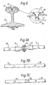
- FIG. 6 One example of the application is in heavy duty electrical engineering with sliding or arcing contact faces where wear and tear take place (Figure 6).
- a cover plate 20 is used with suitable mechanical properties for the arduous duty concerned. Good electrical connection is made between the cover plate 20 and a base conductor rail 21 using methods according to the invention.
- a plug 22 (similar to the component 1 of Figure 1 but with a helical groove 22') is plunged through the cover plate 20 into the rail 21.
- the material 23 displaced by the plug 22 serves to join the cover plate firmly to the base and in addition to provide electrical continuity between the base and cover plate.
- the stud or plug 22 can be of any suitable hard material sufficient to displace the base.
- the tip of the stud 22 can be chamfered (as shown) to assist initial displacement or a preliminary pilot hole drilled in the base or both.
- the stud can be fluted or grooved (as shown) to give a screw like action to help disperse the displaced material at the stud and around its head.
- a stainless steel rubbing plate is attached to an aluminium conductor rail.
- hard steel can be attached to conductor rail of low alloy steel or other suitable alloy.
- a copper rod 37 (Figure 7C) having an end 38 tapered to half its original diameter was joined to a 15mm diameter aluminium rod 39 using a method according to the invention.
- the tapered end 38 was plunged into the rod 39 to a depth equal to its largest diameter and all excess flash was removed.
- the overall resistance of the joint was measured as 2 ⁇ .
- the interface resistances are believed to be in the order of around 6.7 ⁇ (Example 1), 1 ⁇ (Example 2) and 0.6 ⁇ (Example 3).
- the resistance of the friction plunge joint of Figure 7C is an order of magnitude lower than the corresponding bolted connection (Figure 7A).
Landscapes
- Engineering & Computer Science (AREA)
- Mechanical Engineering (AREA)
- Pressure Welding/Diffusion-Bonding (AREA)
Applications Claiming Priority (2)
| Application Number | Priority Date | Filing Date | Title |
|---|---|---|---|
| GB9310469 | 1993-05-20 | ||
| GB939310469A GB9310469D0 (en) | 1993-05-20 | 1993-05-20 | Friction joining |
Publications (2)
| Publication Number | Publication Date |
|---|---|
| EP0627276A2 true EP0627276A2 (fr) | 1994-12-07 |
| EP0627276A3 EP0627276A3 (fr) | 1995-12-20 |
Family
ID=10735866
Family Applications (1)
| Application Number | Title | Priority Date | Filing Date |
|---|---|---|---|
| EP94303363A Withdrawn EP0627276A3 (fr) | 1993-05-20 | 1994-05-10 | Jonction par friction. |
Country Status (6)
| Country | Link |
|---|---|
| EP (1) | EP0627276A3 (fr) |
| JP (1) | JPH0747480A (fr) |
| AU (1) | AU6300994A (fr) |
| CA (1) | CA2123934A1 (fr) |
| GB (1) | GB9310469D0 (fr) |
| NO (1) | NO941885L (fr) |
Cited By (7)
| Publication number | Priority date | Publication date | Assignee | Title |
|---|---|---|---|---|
| DE19746308A1 (de) * | 1997-10-21 | 1999-04-22 | Burkhardt Prof Dr Dr Suthoff | Neuartiges Verfahren zur Herstellung von linienförmigen Schweißverbindungen mittels eines Reibbolzens |
| WO2003000455A1 (fr) * | 2001-06-21 | 2003-01-03 | Black & Decker Inc. | Procede et dispositif d'assemblage d'une ossature en acier au moyen d'une cheville de soudage par friction |
| EP1206996A3 (fr) * | 2000-11-17 | 2003-06-11 | Rolls Royce Plc | Soudage par friction |
| US6769595B2 (en) | 2000-12-20 | 2004-08-03 | Alcoa Inc. | Friction plunge riveting |
| US8020748B2 (en) | 2006-09-12 | 2011-09-20 | Toso SMD, Inc. | Sputtering target assembly and method of making same |
| DE102010046318A1 (de) * | 2010-09-23 | 2012-03-29 | Audi Ag | Fügeelement zum Fügen von wenigstens zwei aneinander liegenden Fügeteilen |
| GB2493744A (en) * | 2011-08-17 | 2013-02-20 | Messier Dowty Ltd | Improved Aircraft Landing Gear Assembly and Method of Manufacture |
Families Citing this family (3)
| Publication number | Priority date | Publication date | Assignee | Title |
|---|---|---|---|---|
| FR2869249B1 (fr) * | 2004-04-27 | 2007-06-29 | Snecma Moteurs Sa | Procede de bouchage, par soudage par friction, d'un trou d'une piece metallique, barre metallique et piece support de palier pour la mise en oeuvre du procede. |
| US9056370B1 (en) * | 2013-10-01 | 2015-06-16 | The Boeing Company | Friction stir weld plugs and methods of using thereof |
| JP7114863B2 (ja) * | 2017-07-03 | 2022-08-09 | 日本軽金属株式会社 | 回転ツール及び接合方法 |
Family Cites Families (10)
| Publication number | Priority date | Publication date | Assignee | Title |
|---|---|---|---|---|
| DE165366C (fr) * | ||||
| CH324404A (de) * | 1952-08-25 | 1957-09-30 | Anstalt Fuer Montage Technik | Zur Aufnahme in einem im Verhältnis zur Länge des eingeschossenen Verankerungsteiles dünnwandigen Körper bestimmtes Verankerungsgeschoss, das diese Wandung nicht ganz durchdringen soll |
| US3144710A (en) * | 1961-05-01 | 1964-08-18 | American Mach & Foundry | Friction sealing |
| FR2321206A1 (fr) * | 1975-08-15 | 1977-03-11 | Welding Inst | Procede de fixation d'une connexion electrique sur une structure |
| JPS59127982A (ja) * | 1983-01-14 | 1984-07-23 | Nissan Motor Co Ltd | 異種部材の摩擦圧接接合方法 |
| FR2544806A1 (fr) * | 1983-04-20 | 1984-10-26 | Studer Norbert | Procede d'assemblage de deux pieces de revolution coaxiales, de meme diametre |
| DE8312420U1 (de) * | 1983-04-27 | 1983-09-22 | Messerschmitt-Bölkow-Blohm GmbH, 8000 München | Aus zwei Teilen zusammengesetztes Drehteil aus je einem Werkstück von hoher und geringerer Festigkeit |
| DE3425079A1 (de) * | 1984-07-07 | 1986-01-30 | thomas technik gesellschaft für magnet- und verfahrenstechnik mbH, 5243 Herdorf | Mit einer welle verbundener koerper |
| GB9125978D0 (en) * | 1991-12-06 | 1992-02-05 | Welding Inst | Hot shear butt welding |
| FR2670541B1 (fr) * | 1991-12-20 | 1993-10-08 | Armand Pinet | Assemblage de deux pieces notamment tubulaires. |
-
1993
- 1993-05-20 GB GB939310469A patent/GB9310469D0/en active Pending
-
1994
- 1994-05-10 AU AU63009/94A patent/AU6300994A/en not_active Abandoned
- 1994-05-10 EP EP94303363A patent/EP0627276A3/fr not_active Withdrawn
- 1994-05-18 JP JP12710094A patent/JPH0747480A/ja not_active Withdrawn
- 1994-05-19 NO NO941885A patent/NO941885L/no unknown
- 1994-05-19 CA CA 2123934 patent/CA2123934A1/fr not_active Abandoned
Cited By (11)
| Publication number | Priority date | Publication date | Assignee | Title |
|---|---|---|---|---|
| DE19746308A1 (de) * | 1997-10-21 | 1999-04-22 | Burkhardt Prof Dr Dr Suthoff | Neuartiges Verfahren zur Herstellung von linienförmigen Schweißverbindungen mittels eines Reibbolzens |
| EP1206996A3 (fr) * | 2000-11-17 | 2003-06-11 | Rolls Royce Plc | Soudage par friction |
| GB2369793B (en) * | 2000-11-17 | 2004-09-01 | Rolls Royce Plc | Friction welding |
| US6769595B2 (en) | 2000-12-20 | 2004-08-03 | Alcoa Inc. | Friction plunge riveting |
| WO2003000455A1 (fr) * | 2001-06-21 | 2003-01-03 | Black & Decker Inc. | Procede et dispositif d'assemblage d'une ossature en acier au moyen d'une cheville de soudage par friction |
| US7165710B2 (en) | 2001-06-21 | 2007-01-23 | Black & Decker Inc. | Method and apparatus for fastening steel framing with a spin weld pin |
| US8020748B2 (en) | 2006-09-12 | 2011-09-20 | Toso SMD, Inc. | Sputtering target assembly and method of making same |
| US8235277B2 (en) | 2006-09-12 | 2012-08-07 | Tosoh Smd, Inc. | Sputtering target assembly and method of making same |
| DE102010046318A1 (de) * | 2010-09-23 | 2012-03-29 | Audi Ag | Fügeelement zum Fügen von wenigstens zwei aneinander liegenden Fügeteilen |
| GB2493744A (en) * | 2011-08-17 | 2013-02-20 | Messier Dowty Ltd | Improved Aircraft Landing Gear Assembly and Method of Manufacture |
| GB2493744B (en) * | 2011-08-17 | 2014-08-27 | Messier Dowty Ltd | Improved aircraft landing gear assembly and method of manufacture |
Also Published As
| Publication number | Publication date |
|---|---|
| AU6300994A (en) | 1994-11-24 |
| GB9310469D0 (en) | 1993-07-07 |
| NO941885D0 (no) | 1994-05-19 |
| NO941885L (no) | 1994-11-21 |
| JPH0747480A (ja) | 1995-02-21 |
| EP0627276A3 (fr) | 1995-12-20 |
| CA2123934A1 (fr) | 1994-11-21 |
Similar Documents
| Publication | Publication Date | Title |
|---|---|---|
| EP0627276A2 (fr) | Jonction par friction | |
| US1776615A (en) | Joint and method of making the same | |
| Gedeon et al. | Resistance spot welding of galvanized steel: Part II. Mechanisms of spot weld nugget formation | |
| US2387154A (en) | Method of joining bus bars | |
| Zhou et al. | Weldability of thin sheet metals during small-scale resistance spot welding using an alternating-current power supply | |
| JPH07505090A (ja) | 摩擦溶接方法 | |
| JP2004522591A (ja) | 摩擦攪拌溶接工具 | |
| CA2958509A1 (fr) | Contact a sertir | |
| JP7348413B2 (ja) | 電気エネルギー伝送継手及びその製造方法 | |
| US4577053A (en) | Ground rod | |
| WO2014019958A2 (fr) | Chalumeau pour le soudage au tungstène et au gaz inerte | |
| GB2306365A (en) | Friction plug extrusion | |
| CN88100633A (zh) | 用热塑材料制做的焊接套筒及其制造方法和制造设备 | |
| US2707826A (en) | Method of making cold welded wire joints | |
| EP3747568A1 (fr) | Raccord de fixation de rivet aveugle, procédé de fabrication d'un raccord de fixation de rivet aveugle et fixation de rivet aveugle | |
| US4279729A (en) | Anode and method of construction | |
| RU2219599C2 (ru) | Тепловыделяющий элемент, способ изготовления тепловыделяющего элемента и устройство для его осуществления | |
| WO1995024291A1 (fr) | Procede d'assemblage par friction | |
| RU2631043C1 (ru) | Неразъёмное соединение деталей замкнутого контура и способ его осуществления | |
| JPH05207708A (ja) | ロータ鉄心とロータバーの接合方法 | |
| KR20000059157A (ko) | 이종금속의 마찰용접 방법 및 그 용접모재 | |
| US4151392A (en) | Method of manufacturing electrical connector | |
| US557174A (en) | Rail bond or connection | |
| US4334122A (en) | Bimetallic electrical connector and method for making such connector | |
| EP0677419A1 (fr) | Connecteur électrique |
Legal Events
| Date | Code | Title | Description |
|---|---|---|---|
| PUAI | Public reference made under article 153(3) epc to a published international application that has entered the european phase |
Free format text: ORIGINAL CODE: 0009012 |
|
| AK | Designated contracting states |
Kind code of ref document: A2 Designated state(s): CH DE FR GB LI SE |
|
| PUAL | Search report despatched |
Free format text: ORIGINAL CODE: 0009013 |
|
| AK | Designated contracting states |
Kind code of ref document: A3 Designated state(s): CH DE FR GB LI SE |
|
| STAA | Information on the status of an ep patent application or granted ep patent |
Free format text: STATUS: THE APPLICATION IS DEEMED TO BE WITHDRAWN |
|
| 18D | Application deemed to be withdrawn |
Effective date: 19960621 |