EP0627353A2 - Direction assistée débrayable - Google Patents
Direction assistée débrayable Download PDFInfo
- Publication number
- EP0627353A2 EP0627353A2 EP94107660A EP94107660A EP0627353A2 EP 0627353 A2 EP0627353 A2 EP 0627353A2 EP 94107660 A EP94107660 A EP 94107660A EP 94107660 A EP94107660 A EP 94107660A EP 0627353 A2 EP0627353 A2 EP 0627353A2
- Authority
- EP
- European Patent Office
- Prior art keywords
- power steering
- clutch
- switchable power
- lubricating oil
- control circuit
- Prior art date
- Legal status (The legal status is an assumption and is not a legal conclusion. Google has not performed a legal analysis and makes no representation as to the accuracy of the status listed.)
- Ceased
Links
Images


Classifications
-
- F—MECHANICAL ENGINEERING; LIGHTING; HEATING; WEAPONS; BLASTING
- F04—POSITIVE - DISPLACEMENT MACHINES FOR LIQUIDS; PUMPS FOR LIQUIDS OR ELASTIC FLUIDS
- F04C—ROTARY-PISTON, OR OSCILLATING-PISTON, POSITIVE-DISPLACEMENT MACHINES FOR LIQUIDS; ROTARY-PISTON, OR OSCILLATING-PISTON, POSITIVE-DISPLACEMENT PUMPS
- F04C14/00—Control of, monitoring of, or safety arrangements for, machines, pumps or pumping installations
- F04C14/28—Safety arrangements; Monitoring
-
- B—PERFORMING OPERATIONS; TRANSPORTING
- B62—LAND VEHICLES FOR TRAVELLING OTHERWISE THAN ON RAILS
- B62D—MOTOR VEHICLES; TRAILERS
- B62D5/00—Power-assisted or power-driven steering
- B62D5/06—Power-assisted or power-driven steering fluid, i.e. using a pressurised fluid for most or all the force required for steering a vehicle
- B62D5/065—Power-assisted or power-driven steering fluid, i.e. using a pressurised fluid for most or all the force required for steering a vehicle characterised by specially adapted means for varying pressurised fluid supply based on need, e.g. on-demand, variable assist
-
- F—MECHANICAL ENGINEERING; LIGHTING; HEATING; WEAPONS; BLASTING
- F04—POSITIVE - DISPLACEMENT MACHINES FOR LIQUIDS; PUMPS FOR LIQUIDS OR ELASTIC FLUIDS
- F04C—ROTARY-PISTON, OR OSCILLATING-PISTON, POSITIVE-DISPLACEMENT MACHINES FOR LIQUIDS; ROTARY-PISTON, OR OSCILLATING-PISTON, POSITIVE-DISPLACEMENT PUMPS
- F04C15/00—Component parts, details or accessories of machines, pumps or pumping installations, not provided for in groups F04C2/00 - F04C14/00
- F04C15/0057—Driving elements, brakes, couplings, transmission specially adapted for machines or pumps
- F04C15/0061—Means for transmitting movement from the prime mover to driven parts of the pump, e.g. clutches, couplings, transmissions
Definitions
- the invention relates to a power steering system which can be switched off and which has a power steering pump which can be driven via the drive machine of a motor vehicle.
- the invention is therefore based on the object of providing a switchable power steering of the generic type in which a safe temporary switch-off of the power steering pump is possible in a simple manner and the latter does not require any additional drive.
- the power steering pump has a hydraulic clutch, preferably via an oil circuit a lubricating oil circuit of the prime mover can be actuated, an existing lubricating oil circuit for the prime mover can advantageously be used to actuate a hydraulic clutch, so that no additional drives are required for the power steering pump and it can still be put out of operation.
- a branch of the lubricating oil circuit leading to the clutch contains a solenoid valve which can be actuated via a control circuit which interacts with the steering of the motor vehicle.
- the control circuit is preferably activated by a sensor, in particular a torque sensor, which reacts to a change (actuation) in the steering of the motor vehicle.
- the sensor can be arranged at any suitable point in the area of the entire steering system of the motor vehicle.
- the torque sensor is assigned to a steering wheel of the motor vehicle, which activates the control circuit when a specific torque on the steering wheel is exceeded.
- control circuit is activated via the torque sensor in the steering wheel so that the solenoid valve opens and thus the oil pressure of the lubricating oil circuit acts on the hydraulic clutch and this disengages the power steering pump.
- the torque circuit arranged in the steering wheel activates the control circuit so that it closes the solenoid valve and at the same time vented the branch of the lubricating oil circuit leading to the hydraulic clutch, so that the hydraulic clutch immediately re-engages the power steering pump and the hydraulic power steering is thus effective.
- the clutch has at least one hydraulic cylinder which can be pressurized via the branch of the lubricating oil circuit and which is preferably required to apply a pressure dependent on a minimum speed of the drive machine to the hydraulic cylinder. This ensures that it is only necessary to start up the drive machine and thus a lubricating oil pump which interacts with the drive machine and which builds up the lubricating oil circuit before the hydraulic clutch can be actuated at all. It is very advantageous here that the lubricating oil pump is only loaded with the additional pressure for actuating the hydraulic clutch when it has built up a safe-acting lubricating oil circuit for engine lubrication.
- This minimum speed can now be selected such that, for example, the power steering pump is only disengaged only on very fast freeway journeys, where the speed, for example over 4000 rpm. lies, takes place.
- this minimum speed can also be set lower, so that the power steering pump can be disengaged even in a low-speed driving style in which the steering is not required.
- the clutch has a first clutch part which can be actuated via the hydraulic cylinder against the force of a spring and which can be brought into or out of engagement with a second constantly rotating clutch part. It is hereby very advantageously achieved that the hydraulic clutch is constantly in the engaged state when the first clutch part is not actuated via the hydraulic cylinder, and thus the power steering pump is in operation. Thus, when the hydraulic cylinder is no longer pressurized from the lubricating oil circuit, the power steering pump is automatically engaged. This immediate engagement increases safety, for example in the event of an accident, in such a way that the power steering pump is always immediately available when it is needed.
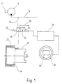
- FIG. 1 shows a drive machine 10 of a motor vehicle, not shown, which is designed, for example, as an internal combustion engine and which, among other things, drives a lubricating oil pump 12.
- a lubricating oil circuit 14 starts from the lubricating oil pump 12 and takes over the lubrication of the drive machine 10, which is not to be considered in more detail here.
- a branch 16 leads from the lubricating oil circuit 14 to a power steering pump 20 provided with a hydraulic clutch 18.
- the power steering pump 20 or the clutch 18 is driven here by a pulley 22 which is connected to the drive machine 10 by a belt (not shown).
- a solenoid valve 24 is arranged, which can be actuated via a control circuit 26.
- the solenoid valve 24 has a switching element 28 which on the one hand can connect the clutch 18 to the branch 16 and on the other hand the clutch in this exemplary embodiment 18 can connect to a connection 30 leading to a tank, not shown here.
- the switching element 28 can be switched against the force of a spring 29.
- the control circuit 26 is connected to a sensor, for example a torque sensor 34, in a steering wheel 32 of the motor vehicle.
- the arrangement shown in Figure 1 performs the following function: After starting the drive machine 10 of the motor vehicle, a pressure is built up in the lubricating oil circuit 14 via the lubricating oil pump 12 and is also applied to the solenoid valve 24 via the branch 16. At the same time, the drive pulley 10 drives the pulley 22 and, via the clutch 18 which is in the engaged state, the power steering pump 20.
- the power steering pump 20 supplies a consumer, not shown here, in particular the steering, with an oil flow or oil pressure.
- the clutch 18 In the initial state, the clutch 18 is in the engaged state and is hydraulically relieved to a tank via the switching element 28 and the connection 30.
- a low manual torque occurs on the steering wheel 32.
- This manual torque is detected by the torque sensor 34 and reported to the control circuit 26.
- the torque sensor 34 assigned to the steering wheel 32 is only exemplary. Detection of the steering of the motor vehicle Forces occurring can occur through any other sensor that can be arranged at a suitable position in the entire steering system of the motor vehicle.
- the solenoid valve 24 is actuated via the control circuit 26, so that the switching element 28 establishes a connection between the branch 16 and the clutch 18.
- the oil pressure in the lubricating oil circuit 14 and the branch 16 is so great that the clutch 18 can be actuated easily.
- the torque sensor 34 sends a corresponding signal to the control circuit 26.
- the control circuit 26 actuates immediately the solenoid valve 24, so that the switching element 28 creates a connection between the clutch 18 and the connection 30 leading to the tank by the force of the spring 29 and the clutch is hydraulically relieved.
- the clutch 18 is engaged under spring force, so that the power steering pump 20 is again connected to its drive and can supply the connected consumer with an oil flow for steering assistance.
- the arrangement of the spring 29 also represents a fail-safe, a so-called “fail safe", in that in the event of a failure of the control circuit 26 by the force of the spring 29 a connection is established between the clutch 18 and the connection 30 and thus relieves the clutch 18 and thus , as already mentioned, is engaged.
- a further failure protection is achieved in that the coupling 18 can only be uncoupled against the force of a spring, not shown in FIG. 1. If the pressure emanating from the lubricating oil pump 12 drops below a certain value, for example due to an emergency situation, the clutch 18 is engaged by the spring. In this way, it is guaranteed in any case that a steering assistance starting from the power steering pump 20 is immediately available.
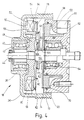
- FIG. 2 shows the power steering pump 20 with the flanged coupling 18.
- the clutch 18 has a part 36 which is connected to the pulley 22 and which accommodates a bearing 40 in an extension 38.
- the bearing 40 is supported in a bearing shell 42, which at the same time receives a shaft 44.
- the shaft 44 has a rotor 46 of the power steering pump 20 at one end.
- a rotationally symmetrical part 48 is fixedly connected to the shaft 44 and ends in a U-shaped area 50 in its outer circumference.
- the area 50 has a fixed leg 52 and a leg 54 which can be moved in the axial direction.
- the clutch 18 also has a fixed part 62 which is connected to the power steering pump 20 and through which the shaft 44 is guided in a bearing 64.
- the part 62 has a channel 66 which can be connected to the branch 18 described in FIG. 1 via the solenoid valve 24 and which opens into an annular space 68.
- a hydraulic cylinder (cylinder piston) 70 is arranged in the annular space 68 and is sealed against the part 62 via seals 72.
- the hydraulic cylinder 70 has on it
- the side 74 facing away from the power steering pump 20 has a nose-like projection 76 which is directed against a plate spring 78.
- the plate spring 78 is mounted in a guide 80 and its end 82 presses against the leg 54. Further details of the mechanical structure of the clutch 18 and the power steering pump 20 will not be discussed further here.
- the arrangement shown in Figure 2 performs the following function:
- the pulley 22 and thus the part 36 are set in rotation via a drive machine, not shown.
- the lamellae connected in the area 60 to the intermediate piece 58 rotate.
- the plate spring 78 By the force of the plate spring 78, the leg 54 is pressed in the direction of the leg 52, so that the lamellae arranged on the base 56 are pressed together in their overlap area with the lamellae arranged on the intermediate piece 58.
- the rotor 46 of the power steering pump 20 With the rotation of the shaft 44, the rotor 46 of the power steering pump 20 is set in rotation and promotes an oil flow to a connected consumer, in particular a steering system, in a manner not to be considered here.
- the hydraulic cylinder 70 is connected to the lubricating oil circuit 14 via the channel 66 and the annular space 68 outgoing pressure.
- the hydraulic cylinder 70 is moved in the axial direction counter to the power steering pump 20 and presses with its projection 76 onto the plate spring 78.
- the plate spring 78 pivots about its guide 80 and thus disengages from the leg 54.
- leg 54 is one Prestressing is eliminated by the loss of the force emanating from the plate spring 78, the pressing pressure on the lamellae arranged in an overlapping manner in the region 60, so that no more force transmission takes place between them.
- the part 36 driven by the pulley 22 continues to rotate, while the part 48 and thus the rotor 46 come to a standstill.
- the power steering pump 20 is out of operation and does not consume its energy loss.
- the channel 66 is vented via the connection 30, as already mentioned for FIG. 1, so that the hydraulic cylinder 70 is pushed back into its starting position via the plate spring 78.
- the plate spring 78 presses again against the leg 54, so that the part 48 is non-positively coupled to the part 36 in the manner already described.
- FIG. 3 shows a further variant of a coupling 18, the same parts as in FIG. 2 being provided with the same reference symbols and not being explained again here.
- the channel 66 opens into an axial bore 84 which creates a connection between the channel 66 and an L-shaped annular space 86.
- the hydraulic cylinder 70 is arranged here in the annular space 86.
- the hydraulic cylinder 70 is associated with a disk-shaped body 88 which has a nose 90 pointing in the radial direction, which bears against one end 92 of the plate spring 78.
- the leg 54 of the U-shaped region 50 has a nose-shaped projection 94, against which the plate spring 78 abuts with its end 82.
- the plate spring 78 is also assigned a holding rivet 96, with which the plate spring 78 is fastened to the coupling.
- FIG. 4 shows the coupling 18 in a further embodiment variant.
- the same parts as in Figures 2 and 3 are again provided with the same reference numerals and not explained again.
- the channel 66 opens into an annular space 98, which has a curved wall 100, which allows the oil to flow favorably onto the hydraulic cylinder 70.
- the hydraulic cylinder 70 has on its side 74 a disc 102 which is guided on a sleeve 104.
- a ring 106 which has a cantilever arm 108, is arranged on the sleeve 104 adjacent to the disk 102.
- the cantilever arm 108 has a nose-like projection 110 which bears against the end 92 of the plate spring 78.
Landscapes
- Engineering & Computer Science (AREA)
- Mechanical Engineering (AREA)
- General Engineering & Computer Science (AREA)
- Chemical & Material Sciences (AREA)
- Combustion & Propulsion (AREA)
- Transportation (AREA)
- Steering Control In Accordance With Driving Conditions (AREA)
- Power Steering Mechanism (AREA)
- Hydraulic Clutches, Magnetic Clutches, Fluid Clutches, And Fluid Joints (AREA)
Applications Claiming Priority (2)
| Application Number | Priority Date | Filing Date | Title |
|---|---|---|---|
| DE19934318933 DE4318933C1 (de) | 1993-06-03 | 1993-06-03 | Abschaltbare Servolenkung |
| DE4318933 | 1993-06-03 |
Publications (2)
| Publication Number | Publication Date |
|---|---|
| EP0627353A2 true EP0627353A2 (fr) | 1994-12-07 |
| EP0627353A3 EP0627353A3 (en) | 1995-12-06 |
Family
ID=6489841
Family Applications (1)
| Application Number | Title | Priority Date | Filing Date |
|---|---|---|---|
| EP94107660A Ceased EP0627353A3 (en) | 1993-06-03 | 1994-05-18 | Switchable power steering. |
Country Status (3)
| Country | Link |
|---|---|
| EP (1) | EP0627353A3 (fr) |
| JP (1) | JPH0752811A (fr) |
| DE (1) | DE4318933C1 (fr) |
Cited By (3)
| Publication number | Priority date | Publication date | Assignee | Title |
|---|---|---|---|---|
| GB2309950A (en) * | 1996-02-05 | 1997-08-13 | Unisia Jecs Corp | Power-assisted steering apparatus for automotive vehicle |
| FR2771067A1 (fr) * | 1997-11-14 | 1999-05-21 | Renault | Direction assistee hydraulique a centre ouvert |
| EP4438443A1 (fr) * | 2023-03-30 | 2024-10-02 | Quanxing Machining Group Co., Ltd. | Pompe de direction d'urgence avec embrayage et procédé de commande associé |
Families Citing this family (1)
| Publication number | Priority date | Publication date | Assignee | Title |
|---|---|---|---|---|
| CN104118473B (zh) * | 2014-07-14 | 2016-04-20 | 阜新德尔汽车部件股份有限公司 | 车辆动力转向用电液泵 |
Family Cites Families (4)
| Publication number | Priority date | Publication date | Assignee | Title |
|---|---|---|---|---|
| DE2260797A1 (de) * | 1972-12-13 | 1974-06-20 | Daimler Benz Ag | Regelbarer aggregate-antrieb fuer brennkraftmaschinen, insbesondere fuer kraftfahrzeug-brennkraftmaschinen |
| EP0044733B1 (fr) * | 1980-07-18 | 1985-01-23 | Nissan Motor Co., Ltd. | Système hydraulique de direction assistée pour véhicule, comportant un dispositif de pilotage de la pompe d'assistance |
| FI71698C (fi) * | 1985-01-09 | 1987-02-09 | Valmet Oy | Kraftoeverfoeringsarrangemang i en traktor. |
| DE3740097A1 (de) * | 1987-11-26 | 1989-06-08 | Gerd Drespa | System zur leistungsausnutzung von verbrennungsmotoren durch externen antrieb der nebenaggregate und deren einsatz zur energiebereitstellung |
-
1993
- 1993-06-03 DE DE19934318933 patent/DE4318933C1/de not_active Expired - Fee Related
-
1994
- 1994-05-18 EP EP94107660A patent/EP0627353A3/de not_active Ceased
- 1994-06-02 JP JP6121448A patent/JPH0752811A/ja active Pending
Cited By (5)
| Publication number | Priority date | Publication date | Assignee | Title |
|---|---|---|---|---|
| GB2309950A (en) * | 1996-02-05 | 1997-08-13 | Unisia Jecs Corp | Power-assisted steering apparatus for automotive vehicle |
| GB2309950B (en) * | 1996-02-05 | 1998-05-13 | Unisia Jecs Corp | Power assisted steering apparatus for automotive vehicle |
| US5921342A (en) * | 1996-02-05 | 1999-07-13 | Unisia Jecs Corporation | Power assisted steering apparatus for automotive vehicle |
| FR2771067A1 (fr) * | 1997-11-14 | 1999-05-21 | Renault | Direction assistee hydraulique a centre ouvert |
| EP4438443A1 (fr) * | 2023-03-30 | 2024-10-02 | Quanxing Machining Group Co., Ltd. | Pompe de direction d'urgence avec embrayage et procédé de commande associé |
Also Published As
| Publication number | Publication date |
|---|---|
| JPH0752811A (ja) | 1995-02-28 |
| EP0627353A3 (en) | 1995-12-06 |
| DE4318933C1 (de) | 1994-07-07 |
Similar Documents
| Publication | Publication Date | Title |
|---|---|---|
| DE2404580C2 (de) | Lenkgetriebe für Fahrzeuge | |
| DE2700324C2 (de) | Hydraulische Steuervorrichtung für ein selbsttätig schaltendes hydrodynamisch- mechanisches Verbundgetriebe von Kraftfahrzeugen | |
| DE3204891C2 (fr) | ||
| EP2145118B1 (fr) | Unité d'actionnement d'embrayage en fonction d'une différence couple/vitesse pour véhicules à moteur | |
| DE3854022T2 (de) | Stufenloses Getriebe. | |
| WO2018054414A1 (fr) | Système d'embrayage multiple et module hybride pour véhicule automobile | |
| EP0728265B1 (fr) | Commande hydraulique de secours pour un embrayage a friction monte entre un moteur a combustion interne et une boite de vitesses | |
| DE10314338A1 (de) | Hydrodynamischer Wandler mit Primär- und Wandlerüberbrückungskupplung | |
| EP3921562B1 (fr) | Système d'actionnement d'un frein de stationnement | |
| DE19851668A1 (de) | Radbremsvorrichtung | |
| DE2238632C2 (de) | Schlingbandfederkupplung mit Rücklaufsperre | |
| DE3433333C2 (de) | Hydraulischer Steuerkreis für ein automatisches Kraftfahrzeuggetriebe | |
| DE3026773C2 (de) | Hydraulische Retardervorrichtung im Antriebsstrang eines Fahrzeuges | |
| EP1436518B1 (fr) | Systeme d'embrayage | |
| DE68907311T2 (de) | Verzögerer. | |
| DE3245720C2 (de) | Antriebsanordnung für einen Dreh-, Schwenk- und Fahrantrieb eines Fahrzeugs, insbesondere für einen Bagger | |
| DE4335602B4 (de) | Kupplungs-Brems-Anordnung | |
| DE2911085A1 (de) | Regeleinrichtung fuer einen kompressor, insbesondere zum betrieb in kraftfahrzeugen | |
| DE3420932C2 (fr) | ||
| EP0627353A2 (fr) | Direction assistée débrayable | |
| DE2163545B2 (de) | Reibungskupplung | |
| EP0305390A1 (fr) | Commande electro-hydraulique pour boite de vitesses automatique. | |
| DE3013382A1 (de) | Kupplungs-brems-kombination mit zwei bremsen | |
| DE1780442C3 (fr) | ||
| DE1052315B (de) | Getriebe mit hydraulischer Steuereinrichtung zum Antrieb von Hubfahrzeugen |
Legal Events
| Date | Code | Title | Description |
|---|---|---|---|
| PUAI | Public reference made under article 153(3) epc to a published international application that has entered the european phase |
Free format text: ORIGINAL CODE: 0009012 |
|
| AK | Designated contracting states |
Kind code of ref document: A2 Designated state(s): DE FR GB IT |
|
| PUAL | Search report despatched |
Free format text: ORIGINAL CODE: 0009013 |
|
| AK | Designated contracting states |
Kind code of ref document: A3 Designated state(s): DE FR GB IT |
|
| 17P | Request for examination filed |
Effective date: 19951130 |
|
| 17Q | First examination report despatched |
Effective date: 19960129 |
|
| GRAG | Despatch of communication of intention to grant |
Free format text: ORIGINAL CODE: EPIDOS AGRA |
|
| STAA | Information on the status of an ep patent application or granted ep patent |
Free format text: STATUS: THE APPLICATION HAS BEEN REFUSED |
|
| 18R | Application refused |
Effective date: 19970113 |