EP0627507A1 - Machine de cardage avec chapeaux mobiles - Google Patents
Machine de cardage avec chapeaux mobiles Download PDFInfo
- Publication number
- EP0627507A1 EP0627507A1 EP94810308A EP94810308A EP0627507A1 EP 0627507 A1 EP0627507 A1 EP 0627507A1 EP 94810308 A EP94810308 A EP 94810308A EP 94810308 A EP94810308 A EP 94810308A EP 0627507 A1 EP0627507 A1 EP 0627507A1
- Authority
- EP
- European Patent Office
- Prior art keywords
- flat
- flat bar
- drive belt
- bar
- hollow profile
- Prior art date
- Legal status (The legal status is an assumption and is not a legal conclusion. Google has not performed a legal analysis and makes no representation as to the accuracy of the status listed.)
- Granted
Links
Images


Classifications
-
- D—TEXTILES; PAPER
- D01—NATURAL OR MAN-MADE THREADS OR FIBRES; SPINNING
- D01G—PRELIMINARY TREATMENT OF FIBRES, e.g. FOR SPINNING
- D01G15/00—Carding machines or accessories; Card clothing; Burr-crushing or removing arrangements associated with carding or other preliminary-treatment machines
- D01G15/02—Carding machines
- D01G15/12—Details
- D01G15/14—Constructional features of carding elements, e.g. for facilitating attachment of card clothing
- D01G15/24—Flats or like members
Definitions
- the invention relates to flat bar arrangements of a revolving flat card.
- the flat bar of a revolving flat card definitely includes a clothing receiving part which has to be connected to a drive device.
- the flat rod can comprise end heads which are to be connected both to the clothing receiving part and to the drive device.
- the invention provides a connection system between a peripheral flat bar of a revolving flat card and a flexible drive belt for the decorative bars according to the preamble of patent claim 1.
- a connection system is known for example from DE-A-3907396 (US-4955111). It is described and shown there in particular (FIG. 4) to provide the end of the cover head with a continuous hollow cylindrical bore and the drive belt with projections which engage in the corresponding bores in the cover heads.
- the cover head shows teeth with tooth gaps, into which corresponding teeth of a double toothed belt engage.
- the flat bars which are located between the flexible bend and the toothed belt, it is important that there are enough guides there.
- the flexible sheet must be deflected so that the flat bars do not fall off the toothed belt. After this deflection, the flat bars can easily be removed from the toothed belt, since they lie freely on them.
- the above device has the disadvantage that the flat bars mechanically during the deflection and partly also on the ascending and descending path of the endless movement loop of the revolving lid (by means of specially provided Means) must be managed. This means an increased, constructive effort.
- connection system for use with a cover chain is known, an end part of a fastening bolt being provided with a continuous slot, so that two webs are created.
- Each bridge has an outward approach.
- the webs are elastic so that the lugs can snap into a slot in the lid head.
- the system requires a fastener (the bolt) that must be connected to the cover chain itself.
- the arrangement has practically no advantages over conventional systems (with a screw instead of a bolt) and has not appeared in practice.
- the object of the invention in the mentioned first aspect is to improve the above-mentioned device in such a way that the flat bars are guided in a very simple and effective manner, particularly in the area of the deflection, and yet the flat bars are connected to the drive belt in an easily replaceable manner.
- This object is achieved by a connection system between a revolving flat bar of a revolving flat card and a flexible drive belt for the flat bars, after which the flat bar is clampably connected to the drive belt.
- the clampable connection is preferably a snap connection.
- the advantages of the present invention in its first aspect are in particular that no additional mechanical deflection guides are now required and a simple and practical connection of the flat bars to the drive belt is ensured during operation.
- the flat bars can be easily removed from the drive belt and replaced.
- the solution according to the invention is not available only in the known flat bars with cuboid-shaped lid heads, but also, for example, in flat bars which are provided with rod-shaped sliding bolts at their ends, for example according to EP-A-567747.
- the invention provides a flat rod which is shaped as a hollow profile and is provided with separately formed end heads.
- Such a flat bar is described, for example, in US-A-4827573, where it consists of a steel tube drawn through a profile shape.
- Solid head pieces are provided on both ends of the cover rod for attachment with a drive belt. These head pieces are connected to the flat rod either by welding or with rivets or screws so that they can be replaced when they have become unusable due to wear.
- the object of the present invention in the second aspect is to provide a connection between the flat rod and the head pieces which is simple and inexpensive to manufacture and which minimizes unnecessary local stresses between the head piece and a hollow flat bar. This object is solved by the features of claim 14.
- the invention in the second aspect has the great advantage that the connection between the head piece and the hollow flat rod is produced in a very cost-effective manner, and nevertheless allows a dimensionally stable and precise connection between these two parts.
- This type of connection is particularly advantageous if light metals, such as aluminum or the like, are used as a hollow profile for the production of flat bars. Due to the low-cost production of such flat bars, it is much more economical if the flat bars are exchanged as a whole, instead of only exchanging the head pieces or head parts.
- the revolving cover set of a card according to DE-A-3835776 comprises, for example, 106 flat bars 1, of which 41 are in the working position, that is to say in contact with the sliding guide.
- Fig. 1 is a perspective view of part of a flat bar 1 on a so-called flexible sheet 2, which serves here as a sliding guide.
- the flat bar 1 has a cavity 3 with a wall 4.
- the flat rod 1 has two reinforcing ribs 5, in which blind hole-like connecting holes 6 are provided. In these holes 6 slide pins 7 are pressed or screwed.
- the flat bar 1 runs on this flexible bolt 7 on the flexible sheet 2.
- the reinforcing ribs 5 are each provided with an upstanding edge 8, so that the clothing (not shown) can easily be applied to the flat bar 1 by flanging.
- FIG. 2 the left bolt 7a belongs to a first flat rod, the middle two bolts 7b to a second flat rod 1 (indicated by dashed lines) and the right bolt 7c to a third flat rod.
- the distance between the bolts 7b is fixed, that is to say cannot be changed, and that the distance, for example, between the bolt 7a and the right-hand bolt 7b can be changed as a function of the pitch of the drive belt 9. This distance is unimportant for the connection system as such.
- the approximately 50 mm wide and 2.5 mm thick Drive belt 9 is now provided in the region of the bolts 7b with a tooth-like projection 10 standing downward.
- This projection has the same curvature to the side of the bolts 7b as the bolts 7b.
- a relief slot 11 is provided in the central region of the projection 10. Since the projection 10 is slightly wider in the lower region than the distance between the bolts 7b, this projection 10 is clamped immovably between the two bolts 7b. Nevertheless, the flat bar can be easily detached from the toothed belt 9, since the two cams 12 of the projection 10 are pressed against one another when the flat bar 1 is pulled away. Likewise, when the flat bar is applied, the sliding bolts 7b are lightly pressed onto the drive belt 9. For this purpose, the edges of the cams 12 facing the bolts 7b are rounded, so that the projection 10 snaps into the space between the two bolts 7b without any problems.
- FIG. 3 shows a second variant of a drive or toothed belt 9.1 in connection with the flat bar according to FIG. 1.
- Two tooth-like projections 10.1 (which are designed similarly to the projection 10 in FIG. 2) encompass the two bolts 7b of the flat bar 1. There is therefore an open space between the two bolts 7b, which is slightly deflected on the gearwheel (not shown) is curved. As a result, the snap connection is somewhat looser, but still remains sufficiently stable to hold the flat bars 1 securely on the toothed belt 9.1.
- each pin 7b is surrounded on both sides by a tooth-like projection 10.2.
- the sides of the projections which are directed toward the bolts 7b are partially designed with an identical curvature as the bolts 7b.
- two such projections 10.2 clamp a bolt 7b of the Flat bars 1.
- Relief slots 11 are again provided between the cams 12 of the projections 10.2, which in this case are somewhat wider than in FIG. 2. As can be seen in FIGS. 2 to 4, the relief slots 11 are approximately the same depth as the height (or depth). the projections 10 or 10.1.
- FIG. 5 shows a fourth possibility of the connection between the drive belt 9.3 and the bolts 7b of the flat bar 1.
- two different types of projections 10.3 and 10.4 are provided, which on the one hand engage between the bolts 7b (projection 10.3) and on the other hand only comprise the right-hand bolt 7b (projection 10.4).
- the direction of movement of the drive belt 9, 9.1, 9.2 or 9.3 is unimportant, since at least one of the bolts 7b of the flat bar always remains stably clamped by the toothed belt during the deflection.
- FIGS. 6 and 6a Another variant of the clamp connection with a drive or toothed belt 9.4 is indicated in FIGS. 6 and 6a.
- the flat bar 1 is not formed here as a hollow profile but as a solid bar and is provided in the usual form with a cuboid end 13 on which a pin 14 is arranged in the center.
- the pin 14 is provided with two outwardly bent leaf springs 15 which engage in a corresponding blind hole 16 in the drive belt 9.4 (FIG. 6a).
- the blind hole 16 can be reinforced accordingly by means of a metal sleeve or the like. To further improve the snap connection, corresponding slots or grooves can also be provided in the metal sleeve. This also has a clamping connection between the flat rod 1 and the drive belt 9.4, the is still easy to solve.
- leaf springs 15 can also be provided in the blind hole 16, so that the pin 14 is clamped by the leaf springs 15. Corresponding slots in pin 14 could also be provided to reinforce the clamping. Alternatively, an annular groove can also be milled in the pin 14 or in the blind hole 16. Instead of leaf springs 15, spring rings or a rubber spring in the form of a rubber ring can also be provided in a groove either in the pin 14 or in the blind hole 16.
- FIGS. 6 and 6a show a further variant of the clamp or snap connection according to FIGS. 6 and 6a.
- the cuboid end 13 of the flat bar is provided there with a through bore 17 which is rounded or chamfered at the top and bottom.
- the projection 10.5 is similar to the projections described with reference to FIGS. 1 to 5. Again, the cams 12 are rounded off at the edges pointing outwards, so that a safe "engagement and disengagement" is ensured.
- only one blind hole could be provided in the cuboid end 13, in which case the projection 10.5 shown in the clamped state is always under elastic tension, i.e. the cams 12 are pressed against one another at their ends and the slot 11 has a tapered configuration.
- the protrusions 10 can be reinforced with glass fibers or the like so that they become even more resistant.
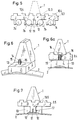
- a flat bar 31 is shown with a back part 32 and a clothing receiving part 33.
- a sawtooth-like set (not shown here) clamped, for which purpose two projections 34 are provided with obliquely inwardly extending holding surfaces 35.
- Head pieces 36 are attached to the outer ends of the cover rod 31, only one of which is visible in the figure.
- the head piece 36 also has a threaded bore 37.
- FIG. 8 also shows that recesses or guides 39 are provided on the inner wall 38 of the back part 32 and extend in the longitudinal direction of the flat bar 31.
- the head piece 36 now consists of a head part 40 and an insertion part 41.
- the insertion part 41 is designed such that it is guided between the recesses 39 and the bottom region 42 of the clothing receiving part 33 with more or less play.
- the rectangular cross-section of the insertion part 41 is in the region of the sides and the underside by a fold of a few millimeters less than the rectangular cross-section of the head part 40. This results in a type of stop or shoulders in order to position the head part 36 exactly with respect to the flat bar 31 .
- Fig. 10 is a cross section through the flat bar 31 with the head piece 36 of FIG. 8 in a vertical plane to a recess or a groove 43 in Fig. 9, before establishing the connection between the insertion part 41 of the head piece 36 and the Hollow flat rod 31.
- the rectangular recesses or guides 39 can be seen, which correspond to the height of the insertion part 41 pushed into the cover rod 31 (see FIG. 8).
- These recesses or guides 39 like the entire profile shape - extend over the entire length of the flat bar 31.
- two of the rectangular recesses or grooves 43 are provided on each side, extending from the upper edge to approximately the middle of the insertion part 41 extend.
- These recesses or grooves 43 have rectangular (sharp) edges 44 there, as do the lateral incisions of the grooves 43.
- punches 45 are provided in order to press the wall 38 of the back part 32 in the region of the recesses 39 against the insertion part 41 (indicated by two arrows). These punches 45 are simultaneously pressed into the predetermined areas of the wall of the flat bar 31 using a pressing device (not indicated here) - that is to say exactly opposite the rectangular recesses or grooves 43 - so that the pressing forces are uniformly distributed on both sides to the wall 38 and to the insertion part 41 is made.
- the length of the insertion part 41 is chosen so that tilting of the head piece 36 is prevented.
- the underside of the head part 40 serves as a sliding surface on the flexible arch of the card, and a torque is generated on the head piece 36 by the chain or belt drive.
- connection 46 This now creates a positive connection 46, as is clearly visible in FIG. 11.
- the insertion part 41 is held by the wall 38, which has been pressed into the area of the sharp edges 44 and the lateral, sharp edges of the grooves 43 by bending or stamping with the punches 45.
- the insertion part 41 is guided on the upper side through the rectangular recesses or guides 39 and through the bottom region 42 of the clothing receiving part 33 without play and on the other hand is fixed by the four connections 46.
- the wall thickness of the back part 32 in the area of the connection 46 is somewhat less than the usual wall thickness, which is in the range from 1 to 3 mm and is preferably approximately 2 mm. This prevents the sharp, rectangular edges 44 from tearing or causing slight breaks. Furthermore, this also makes connection 46 easier to manufacture. This creates a very stable and inexpensive connection between the head piece 36 and the hollow flat rod 31.
- the recesses or grooves 43 can also be provided with rounded edges, which is particularly the case when embossing into the insertion part 41.
- the recesses 43 do not necessarily have to be rectangular, but the same function can be achieved if they have a round shape.
- the punches 45 naturally also have a correspondingly round shape, so that the material of the wall 42 is pressed into the recesses 39 in a form-fitting manner.
- the width of the clothing receiving part or foot part 33 of the flat bar 31 is denoted by "a", the height of the flat bar 31 by “h”, the minimum width of the back part 32 by “b” and the maximum width by “c”.
- the back part 32 can be almost rectangular over the entire height, and does not necessarily have to have a roof-shaped tapering part, as in the above-mentioned US-A-4827573, in order to have the required bending stiffness and torsional strength.
- the cover rod 31 with the profile shape shown in FIG. 10 is pulled when a steel tube is used, but if aluminum is used, it is pressed through a suitable profile shape (so-called extrusion). With the metals steel and aluminum, the flat bars are manufactured by so-called cold forming. These forming processes are known per se and are therefore not described further here. It is understood from the above description that the recesses 39 in the wall of the flat bar 31 basically only have to match the grooves 43 in the insertion part 41 in order to connect the connections 46 to manufacture.
- the head piece 36 itself is preferably made of cast iron, but can also be made of another stable metal. It should be noted here that the underside of the head part 40 should be hard enough to prevent unnecessary and rapid wear.
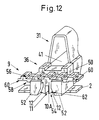
- Figure 12 shows the preferred embodiment based on a combination of the first aspect with the second aspect of the invention.
- a head piece 36 again comprises an insertion part 41.
- the head piece 36 is also provided with a sliding part 50 which is guided along the flexible sheet 2 in the working position of the flat bar and when a rail (not shown) runs back.
- the slide section 50 is provided with two attachments 52 and the two attachments 52 together form a receiving opening 54.
- the flat bar 31 is unchanged from the embodiment according to FIG. 8 - it is therefore only partially (schematically) shown in FIG. 12 and will not be repeated described in connection with Fig. 12.
- the drive belt 9 is formed as a toothed belt.
- the teeth on the "inner surface” 56 of the belt ie on the surface 56 facing inward of the closed path from the circumferential path) cooperate with drive wheels (not shown).
- Recesses 60 are provided in pairs on the "outer surface” 58 of the belt, which faces the flexible sheet 2 in the working position of the flat bars, the recesses 60 each receiving an attachment 52.
- the belt 9 has between the cutouts 60 of each pair a protrusion 10A formed integrally with the belt and constituting a connecting element according to this invention.
- the projection 10A is received in the receiving opening 54 between the attachments 52.
- the projection has a slot 11, whereby two "legs" are formed, each of which is provided with a cam 12 in the foot area.
- the attachments 52 each have an inclined surface 62 in order to be able to better accommodate and hold the cams 12.
- the legs can be pressed together elastically in order to form a snap connection with the head part 36 of the flat bar 31.
- connection that is created between the projection 10A and the attachments 52 is strong enough on the one hand to hold the lid rod on the belt (even when it is no longer guided through the arch 2) and to transmit the drive forces, and on the other hand through an operator can be (manually) released without special tools. Since no additional (loose) elements are necessary, the manufacturing costs can be kept low and the assembly / disassembly can be carried out efficiently.
- the material pairing of the sliding part of the flat bar / sliding guide of the bow can be optimally adapted and the production of the body receiving the flat bar from the flat bar can nevertheless be carried out as inexpensively as possible, with the strength and weight of this body being optimally selected.
- the projecting connecting element is provided on the belt and the receiving part on the rod. This is not absolutely necessary, cf. 6, but preferred because it will be relatively difficult to provide a through hole in the belt, so that a projecting connector can extend through the belt without disturbing the drive system (not shown).
Landscapes
- Engineering & Computer Science (AREA)
- Textile Engineering (AREA)
- Preliminary Treatment Of Fibers (AREA)
Applications Claiming Priority (6)
| Application Number | Priority Date | Filing Date | Title |
|---|---|---|---|
| CH165093 | 1993-06-03 | ||
| CH1650/93 | 1993-06-03 | ||
| CH165093 | 1993-06-03 | ||
| CH248893 | 1993-08-20 | ||
| CH2488/93 | 1993-08-20 | ||
| CH248893 | 1993-08-20 |
Publications (3)
| Publication Number | Publication Date |
|---|---|
| EP0627507A1 true EP0627507A1 (fr) | 1994-12-07 |
| EP0627507B1 EP0627507B1 (fr) | 1998-04-01 |
| EP0627507B2 EP0627507B2 (fr) | 2003-08-27 |
Family
ID=25688268
Family Applications (1)
| Application Number | Title | Priority Date | Filing Date |
|---|---|---|---|
| EP94810308A Expired - Lifetime EP0627507B2 (fr) | 1993-06-03 | 1994-05-27 | Machine de cardage avec chapeaux mobiles |
Country Status (3)
| Country | Link |
|---|---|
| US (1) | US5542154A (fr) |
| EP (1) | EP0627507B2 (fr) |
| DE (1) | DE59405557D1 (fr) |
Cited By (8)
| Publication number | Priority date | Publication date | Assignee | Title |
|---|---|---|---|---|
| DE19534617A1 (de) * | 1994-10-24 | 1996-04-25 | Rieter Ag Maschf | Deckelantriebssystem |
| EP0753610A1 (fr) * | 1995-07-14 | 1997-01-15 | Maschinenfabrik Rieter Ag | Carde à chapeaux mobiles |
| EP0794272A1 (fr) * | 1996-03-04 | 1997-09-10 | F.LLi Marzoli & C. S.p.A. | Dispositif pour guider et assembler le chapeau glissant avec la courroie de commande dans une carde à chapeaux |
| EP0794271A1 (fr) * | 1996-03-04 | 1997-09-10 | F.LLi Marzoli & C. S.p.A. | Carde à chapeaux avec courroie dentée de commande et guidage supérieur pour les chapeaux |
| WO2007071087A1 (fr) * | 2005-12-21 | 2007-06-28 | Maschinenfabrik Rieter Ag | Barre de chapeau pour carde |
| WO2008046479A1 (fr) * | 2006-10-19 | 2008-04-24 | Oerlikon Textile Gmbh & Co. Kg | Dispositif à chapeaux tournants pour une carde |
| DE102006049342A1 (de) * | 2006-10-19 | 2008-04-24 | Oerlikon Textile Gmbh & Co. Kg | Wanderdeckelaggregat für eine Karde |
| DE102012006557A1 (de) * | 2012-04-02 | 2013-10-02 | Trützschler GmbH & Co Kommanditgesellschaft | Deckelstab für eine Karde, der einen Tragkörper mit einem Garnituraufnahmeteil und eine Rückenteil aufweist |
Families Citing this family (15)
| Publication number | Priority date | Publication date | Assignee | Title |
|---|---|---|---|---|
| IT1273727B (it) * | 1994-07-22 | 1997-07-09 | Marzoli & C Spa | Cappello strisciante perfezionato per dispositivi di cardatura e sistema per la sua guida e trascinamento |
| DE59804953D1 (de) | 1997-02-24 | 2002-09-05 | Rieter Ag Maschf | Hochleistungskarde |
| DE59806797D1 (de) * | 1997-09-12 | 2003-02-06 | Rieter Ag Maschf | Kardendeckel |
| DE19825317B4 (de) * | 1998-06-05 | 2010-01-14 | TRüTZSCHLER GMBH & CO. KG | Vorrichtung an einer Karde mit wanderndem Deckel aus mit Garnitur versehenen Deckelstäben |
| DE59914337D1 (de) * | 1998-09-09 | 2007-06-21 | Rieter Ag Maschf | Schleifen von Garnituren |
| US6269522B1 (en) * | 1998-11-24 | 2001-08-07 | Graf & Cie Ag | Method of operating a card and a card flat for carrying out the method |
| IT1319759B1 (it) * | 2000-12-28 | 2003-11-03 | Marzoli Spa | Sistema di guida e trascinamento dei cappelli mobili in una carda acappelli |
| IT1319761B1 (it) * | 2000-12-28 | 2003-11-03 | Marzoli Spa | Dispositivo di pulizia delle guide per i cappelli mobili in una cardaa cappelli |
| WO2002068739A1 (fr) * | 2001-02-24 | 2002-09-06 | Maschinenfabrik Rieter Ag | Pince pour bandes de garniture |
| EP1270777B1 (fr) | 2001-06-21 | 2005-09-21 | Maschinenfabrik Rieter Ag | Assemblage par emboîtement vérouillé entre chapeau de carde et courroie d'entraînement |
| DE10216067A1 (de) * | 2002-04-11 | 2003-10-23 | Rieter Ag Maschf | Deckelendkopf aus Polymerwerkstoff |
| EP1697569B1 (fr) * | 2003-06-03 | 2008-01-16 | Maschinenfabrik Rieter Ag | Surface d'appui et element d'appui |
| DE10358257B4 (de) * | 2003-12-11 | 2015-03-12 | Trützschler GmbH & Co Kommanditgesellschaft | Deckelstab für eine Karde, der einen Tragkörper mit einem Garnituraufnahmeteil aufweist, bei dem dem Tragkörper zwei Endkopfteile zugeordnet sind und Verfahren zu seiner Herstellung |
| EP2026294B1 (fr) * | 2006-04-04 | 2013-03-20 | Glory Ltd. | Machine de reception/distribution de pieces de monnaie |
| DE102019109233A1 (de) * | 2019-04-09 | 2020-10-15 | TRüTZSCHLER GMBH & CO. KG | Deckelstab für eine Karde |
Citations (7)
| Publication number | Priority date | Publication date | Assignee | Title |
|---|---|---|---|---|
| DE384195C (de) * | 1922-10-14 | 1923-11-08 | Eberhard Baltz Dipl Ing | Deckel fuer Krempel |
| DE409319C (de) * | 1923-08-05 | 1925-02-03 | Werke Akt Ges Deutsche | Deckel fuer Krempeln |
| GB870424A (en) * | 1959-02-05 | 1961-06-14 | Schubert & Salzer Maschinen | Improvements in driving means for carding engine flats |
| EP0144184A1 (fr) * | 1983-11-23 | 1985-06-12 | Carding Specialists (Canada) Limited | Cardes |
| US4827573A (en) * | 1985-02-15 | 1989-05-09 | Hans Kuehl | Top bar |
| DE3814412A1 (de) * | 1988-04-28 | 1989-11-09 | Truetzschler & Co | Deckelstab fuer karden |
| WO1992014873A1 (fr) * | 1991-02-13 | 1992-09-03 | Carclo Engineering Group Plc | Chapeaux tournants pour machines a carder |
Family Cites Families (6)
| Publication number | Priority date | Publication date | Assignee | Title |
|---|---|---|---|---|
| GB1353735A (en) † | 1970-07-07 | 1974-05-22 | Carding Spec Canada | Carding means |
| DE3907396C2 (de) * | 1988-09-24 | 1998-07-16 | Truetzschler Gmbh & Co Kg | Vorrichtung an einer Karde mit wanderndem Deckel aus mit Garnitur versehenen Deckelstäben |
| IT8921641A0 (it) * | 1988-09-24 | 1989-09-06 | Truetzschler & Co | Dispositivo su una carda con cappello mobile fatto di sbarra provviste di guarnizioni. |
| DE3835776A1 (de) * | 1988-10-20 | 1990-04-26 | Rieter Ag Maschf | Karde mit modularer unterteilung der kardierzonen |
| DE4304148B4 (de) * | 1992-04-30 | 2008-03-13 | TRüTZSCHLER GMBH & CO. KG | Deckelstab für eine Karde |
| DE9218036U1 (de) † | 1992-04-30 | 1993-06-24 | Trützschler GmbH & Co KG, 4050 Mönchengladbach | Deckelstab für eine Karde |
-
1994
- 1994-05-27 DE DE59405557T patent/DE59405557D1/de not_active Expired - Fee Related
- 1994-05-27 EP EP94810308A patent/EP0627507B2/fr not_active Expired - Lifetime
- 1994-06-02 US US08/253,255 patent/US5542154A/en not_active Expired - Lifetime
Patent Citations (7)
| Publication number | Priority date | Publication date | Assignee | Title |
|---|---|---|---|---|
| DE384195C (de) * | 1922-10-14 | 1923-11-08 | Eberhard Baltz Dipl Ing | Deckel fuer Krempel |
| DE409319C (de) * | 1923-08-05 | 1925-02-03 | Werke Akt Ges Deutsche | Deckel fuer Krempeln |
| GB870424A (en) * | 1959-02-05 | 1961-06-14 | Schubert & Salzer Maschinen | Improvements in driving means for carding engine flats |
| EP0144184A1 (fr) * | 1983-11-23 | 1985-06-12 | Carding Specialists (Canada) Limited | Cardes |
| US4827573A (en) * | 1985-02-15 | 1989-05-09 | Hans Kuehl | Top bar |
| DE3814412A1 (de) * | 1988-04-28 | 1989-11-09 | Truetzschler & Co | Deckelstab fuer karden |
| WO1992014873A1 (fr) * | 1991-02-13 | 1992-09-03 | Carclo Engineering Group Plc | Chapeaux tournants pour machines a carder |
Cited By (13)
| Publication number | Priority date | Publication date | Assignee | Title |
|---|---|---|---|---|
| DE19534617A1 (de) * | 1994-10-24 | 1996-04-25 | Rieter Ag Maschf | Deckelantriebssystem |
| EP0753610A1 (fr) * | 1995-07-14 | 1997-01-15 | Maschinenfabrik Rieter Ag | Carde à chapeaux mobiles |
| US5956811A (en) * | 1995-07-14 | 1999-09-28 | Rieter Machine Works, Ltd. | Revolving flat card |
| EP0794271A1 (fr) * | 1996-03-04 | 1997-09-10 | F.LLi Marzoli & C. S.p.A. | Carde à chapeaux avec courroie dentée de commande et guidage supérieur pour les chapeaux |
| US5745955A (en) * | 1996-03-04 | 1998-05-05 | F.Lli Marzoli & C. S.P.A. | Flat card with toothed belt drive and upper guide for the flats |
| US5749126A (en) * | 1996-03-04 | 1998-05-12 | F.Lli Marzoli & C. S.P.A. | Device for guiding and coupling the sliding flat with the drive belt in a flat card |
| EP0794272A1 (fr) * | 1996-03-04 | 1997-09-10 | F.LLi Marzoli & C. S.p.A. | Dispositif pour guider et assembler le chapeau glissant avec la courroie de commande dans une carde à chapeaux |
| WO2007071087A1 (fr) * | 2005-12-21 | 2007-06-28 | Maschinenfabrik Rieter Ag | Barre de chapeau pour carde |
| WO2008046479A1 (fr) * | 2006-10-19 | 2008-04-24 | Oerlikon Textile Gmbh & Co. Kg | Dispositif à chapeaux tournants pour une carde |
| DE102006049342A1 (de) * | 2006-10-19 | 2008-04-24 | Oerlikon Textile Gmbh & Co. Kg | Wanderdeckelaggregat für eine Karde |
| DE102006049341A1 (de) * | 2006-10-19 | 2008-04-24 | Oerlikon Textile Gmbh & Co. Kg | Wanderdeckelaggregat für eine Karde |
| WO2008046480A1 (fr) * | 2006-10-19 | 2008-04-24 | Oerlikon Textile Gmbh & Co. Kg | Dispositif à chapeaux tournants pour une carde |
| DE102012006557A1 (de) * | 2012-04-02 | 2013-10-02 | Trützschler GmbH & Co Kommanditgesellschaft | Deckelstab für eine Karde, der einen Tragkörper mit einem Garnituraufnahmeteil und eine Rückenteil aufweist |
Also Published As
| Publication number | Publication date |
|---|---|
| DE59405557D1 (de) | 1998-05-07 |
| EP0627507B2 (fr) | 2003-08-27 |
| EP0627507B1 (fr) | 1998-04-01 |
| US5542154A (en) | 1996-08-06 |
Similar Documents
| Publication | Publication Date | Title |
|---|---|---|
| EP0627507B1 (fr) | Machine de cardage avec chapeaux mobiles | |
| DE68905200T2 (de) | Plattenlocher. | |
| DE2112257A1 (de) | Auswechselbarer Zahn | |
| DE4005369C2 (de) | Schließeinrichtung an einer Fahrzeugtür | |
| WO2007014746A1 (fr) | Unite d'assemblage pour extremites libres de moyen de traction | |
| DE3724354C2 (fr) | ||
| EP3771847A1 (fr) | Attache de courroie et courroie | |
| DE19923487B4 (de) | Widerlager mit Formteil zum Befestigen von Betätigungszügen | |
| CH639705A5 (de) | Loesbare verbindung zwischen einem webschaft und einer steigplatine. | |
| DE102016101466B4 (de) | Fahrradbremse | |
| EP3445998B1 (fr) | Maillon de chaîne pour chaîne porte-câbles et chaîne porte-câbles | |
| EP0130138B1 (fr) | Elément de chaîne à maillons ronds | |
| EP0937214B1 (fr) | Dispositif de fixation avec un maillon et une unite de fixation pour lignes | |
| DE2056723A1 (de) | Türschild oder Rosette | |
| DE1775034B1 (de) | Loesbare nutfederverbindung zur halterung streifen und platten foermiger bauteile insbesondere fuer abstreichleisten an papiermaschinen | |
| EP0753610B1 (fr) | Carde à chapeaux mobiles | |
| DE3139735A1 (de) | Kabelfuehrungskette | |
| DE19504038C2 (de) | Gerüst | |
| DE2723551B2 (de) | Gleisstopfpickel | |
| EP0791759A1 (fr) | Boulon à connexion rapide | |
| DE112017000014B4 (de) | Endbefestigung für einen Zahnriemen sowie Verfahren zum Befestigen eines Endes eines Zahnriemens | |
| DE19733023C1 (de) | Gestell, insbesondere für Möbel, aus lösbar durch einen Verbinder miteinander kuppelbaren Profilstangen | |
| DE9015597U1 (de) | Stangenverschluß mit lösbarer Stangenverbindung | |
| DE3037655C2 (fr) | ||
| DE820672C (de) | Einstellbarer Lenker |
Legal Events
| Date | Code | Title | Description |
|---|---|---|---|
| PUAI | Public reference made under article 153(3) epc to a published international application that has entered the european phase |
Free format text: ORIGINAL CODE: 0009012 |
|
| AK | Designated contracting states |
Kind code of ref document: A1 Designated state(s): CH DE GB IT LI |
|
| 17P | Request for examination filed |
Effective date: 19941006 |
|
| 17Q | First examination report despatched |
Effective date: 19951002 |
|
| GRAG | Despatch of communication of intention to grant |
Free format text: ORIGINAL CODE: EPIDOS AGRA |
|
| GRAG | Despatch of communication of intention to grant |
Free format text: ORIGINAL CODE: EPIDOS AGRA |
|
| GRAH | Despatch of communication of intention to grant a patent |
Free format text: ORIGINAL CODE: EPIDOS IGRA |
|
| GRAH | Despatch of communication of intention to grant a patent |
Free format text: ORIGINAL CODE: EPIDOS IGRA |
|
| GRAA | (expected) grant |
Free format text: ORIGINAL CODE: 0009210 |
|
| AK | Designated contracting states |
Kind code of ref document: B1 Designated state(s): CH DE GB IT LI |
|
| REG | Reference to a national code |
Ref country code: CH Ref legal event code: EP |
|
| REF | Corresponds to: |
Ref document number: 59405557 Country of ref document: DE Date of ref document: 19980507 |
|
| ITF | It: translation for a ep patent filed | ||
| PG25 | Lapsed in a contracting state [announced via postgrant information from national office to epo] |
Ref country code: LI Free format text: LAPSE BECAUSE OF NON-PAYMENT OF DUE FEES Effective date: 19980531 Ref country code: CH Free format text: LAPSE BECAUSE OF NON-PAYMENT OF DUE FEES Effective date: 19980531 |
|
| GBT | Gb: translation of ep patent filed (gb section 77(6)(a)/1977) |
Effective date: 19980511 |
|
| PLBI | Opposition filed |
Free format text: ORIGINAL CODE: 0009260 |
|
| REG | Reference to a national code |
Ref country code: CH Ref legal event code: PL |
|
| PLBF | Reply of patent proprietor to notice(s) of opposition |
Free format text: ORIGINAL CODE: EPIDOS OBSO |
|
| 26 | Opposition filed |
Opponent name: TRUETZSCHLER GMBH & CO. KG Effective date: 19981221 |
|
| PLBF | Reply of patent proprietor to notice(s) of opposition |
Free format text: ORIGINAL CODE: EPIDOS OBSO |
|
| PLBF | Reply of patent proprietor to notice(s) of opposition |
Free format text: ORIGINAL CODE: EPIDOS OBSO |
|
| PLBF | Reply of patent proprietor to notice(s) of opposition |
Free format text: ORIGINAL CODE: EPIDOS OBSO |
|
| PLBO | Opposition rejected |
Free format text: ORIGINAL CODE: EPIDOS REJO |
|
| APAC | Appeal dossier modified |
Free format text: ORIGINAL CODE: EPIDOS NOAPO |
|
| APAE | Appeal reference modified |
Free format text: ORIGINAL CODE: EPIDOS REFNO |
|
| APAC | Appeal dossier modified |
Free format text: ORIGINAL CODE: EPIDOS NOAPO |
|
| PGFP | Annual fee paid to national office [announced via postgrant information from national office to epo] |
Ref country code: GB Payment date: 20010423 Year of fee payment: 8 |
|
| REG | Reference to a national code |
Ref country code: GB Ref legal event code: IF02 |
|
| PG25 | Lapsed in a contracting state [announced via postgrant information from national office to epo] |
Ref country code: GB Free format text: LAPSE BECAUSE OF NON-PAYMENT OF DUE FEES Effective date: 20020527 |
|
| GBPC | Gb: european patent ceased through non-payment of renewal fee |
Effective date: 20020527 |
|
| APAC | Appeal dossier modified |
Free format text: ORIGINAL CODE: EPIDOS NOAPO |
|
| PLAW | Interlocutory decision in opposition |
Free format text: ORIGINAL CODE: EPIDOS IDOP |
|
| PUAH | Patent maintained in amended form |
Free format text: ORIGINAL CODE: 0009272 |
|
| STAA | Information on the status of an ep patent application or granted ep patent |
Free format text: STATUS: PATENT MAINTAINED AS AMENDED |
|
| 27A | Patent maintained in amended form |
Effective date: 20030827 |
|
| AK | Designated contracting states |
Designated state(s): CH DE GB IT LI |
|
| EN | Fr: translation not filed | ||
| PGFP | Annual fee paid to national office [announced via postgrant information from national office to epo] |
Ref country code: DE Payment date: 20050520 Year of fee payment: 12 |
|
| APAH | Appeal reference modified |
Free format text: ORIGINAL CODE: EPIDOSCREFNO |
|
| PGFP | Annual fee paid to national office [announced via postgrant information from national office to epo] |
Ref country code: IT Payment date: 20060531 Year of fee payment: 13 |
|
| PG25 | Lapsed in a contracting state [announced via postgrant information from national office to epo] |
Ref country code: DE Free format text: LAPSE BECAUSE OF NON-PAYMENT OF DUE FEES Effective date: 20061201 |
|
| PG25 | Lapsed in a contracting state [announced via postgrant information from national office to epo] |
Ref country code: IT Free format text: LAPSE BECAUSE OF NON-PAYMENT OF DUE FEES Effective date: 20070527 |