EP0627696A2 - Appareil de détection de vecteurs de mouvement d'image - Google Patents
Appareil de détection de vecteurs de mouvement d'image Download PDFInfo
- Publication number
- EP0627696A2 EP0627696A2 EP19940108519 EP94108519A EP0627696A2 EP 0627696 A2 EP0627696 A2 EP 0627696A2 EP 19940108519 EP19940108519 EP 19940108519 EP 94108519 A EP94108519 A EP 94108519A EP 0627696 A2 EP0627696 A2 EP 0627696A2
- Authority
- EP
- European Patent Office
- Prior art keywords
- fourier transform
- output
- discrete fourier
- motion vector
- circuit
- Prior art date
- Legal status (The legal status is an assumption and is not a legal conclusion. Google has not performed a legal analysis and makes no representation as to the accuracy of the status listed.)
- Granted
Links
Images




Classifications
-
- G—PHYSICS
- G06—COMPUTING OR CALCULATING; COUNTING
- G06T—IMAGE DATA PROCESSING OR GENERATION, IN GENERAL
- G06T7/00—Image analysis
- G06T7/20—Analysis of motion
- G06T7/262—Analysis of motion using transform domain methods, e.g. Fourier domain methods
Definitions
- the present invention relates to a motion vector detecting method in image signal processing.
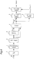
- Fig. 8 is a block diagram of a conventional apparatus detecting motion vectors in a frequency area.
- a discrete Fourier transform means 81 applies a discrete Fourier transformation to an input video signal 800.
- a memory 82 stores one frame of data.
- a divider 83 takes as inputs the outputs from the discrete Fourier transform means 81 and the memory 82, and divides the values for each sampling point.
- a judge circuit 84 takes the output of the divider 83 as its input, and determines the presence of a motion vector in the divider 83 output; if a motion vector is present, the judge circuit 84 then determines the magnitude and direction of the vector.
- Fig. 9 is used to describe motion vector detection apparatus operation.
- Image frame 92 is the frame at time (n+1).
- the difference between n and (n+1) expresses the time interval of one frame to the next frame.
- the signal level of the image at time (n+1) at position x is expressed as g(x).
- a Fourier transform result 93 is obtained by the discrete Fourier transform means 81 applying a discrete Fourier transformation to one image frame 91 at time n.
- Equation 1 is the definition when x is a continuous variable. While x is a discrete value in a digital system, the characteristics of the equation is essentially the same whether x is a continuous or discrete variable, and x is therefore treated as a continuous variable for simplicity. Because the output signal also becomes a discrete value when the input signal is Fourier transformed (depending on the discrete Fourier transform method), ⁇ in equation 1 is also a discrete variable, but can be similarly treated as a continuous variable for the reasons described above.
- the Fourier transform output G( ⁇ ) is expressed by equation 2 similarly to equation 1.
- G( ⁇ ) ⁇ g(x)e -j ⁇ x dx [2]
- the one image frame 91 at time n is referred to as the "previous frame”
- the one image frame 92 at time (n+1) as the "current frame.”
- the output of the memory 82 expresses the Fourier transform result 93 (Fig. 9), i.e., F( ⁇ ), with the previous frame
- the output of the discrete Fourier transform means 81 expresses the Fourier transform result 94 with the current frame, i.e., G( ⁇ ).
- the discrete Fourier transform means 81 (Fig. 8) Fourier transforms the input video signal 800 to obtain the data of the frequency area.
- the input video signal 800 converted to frequency area data is then input to the memory 82, which stores one screen of data.
- the output from memory 82 is the data for the one frame preceding the signal input to the memory 82.
- the discrete Fourier transform output of the current frame (time n+1) is thus equivalent to G( ⁇ )
- the output from the memory 82 is equivalent to the discrete Fourier transform output F( ⁇ ) of the previous frame (time n).
- the divider 83 then divides the output of the memory 82 by the output of the discrete Fourier transform means 81, and outputs the quotient G( ⁇ )/F( ⁇ ).
- the divider output G( ⁇ )/F( ⁇ ) is defined as shown in equation 5, and can be expressed as a simple exponential function.
- a is a two-dimensional vector in a real area (x plane).
- G( ⁇ )/F( ⁇ ) e -j ⁇ a [5]
- the judge circuit 84 detects motion vector a based on this information. Specifically, the judge circuit 84 calculates the motion vector based on the output from divider 83, and determines this to be the motion vector between the previous frame 91 and the current frame 92. The judge circuit 84 calculates the motion vectors as described below, for example.
- Parameter a expressing the position at which this peak appears can be nothing other the amount of parallel displacement assumed in equation 3.
- the motion vector quantity is expressed by the distance (magnitude) and direction from the origin to point a. This is how the judge circuit 84 detects motion vectors.
- the object of the invention is to provide a motion vector detection apparatus whereby motion vectors can be calculated with good precision using few calculations.
- the motion vector detection apparatus of the invention comprises a subsampling means for time-base sampling an input video signal; a discrete Fourier transform means for applying a discrete Fourier transform to the output of the subsampling means; a storage means for storing a one screen equivalent of the output from the discrete Fourier transform means; a divider; an inverse discrete Fourier transform means; and a first evaluation means.
- the subsampling means time-base samples the input video signal
- the discrete Fourier transform means discrete Fourier transforms the subsampled data to convert the real area to frequency area data.
- the data for these frequency areas in the previous and current frames is then divided by the divider by retrieving the discrete Fourier transform output obtained from the previous frame from the storage means to divide the previous frame data with the discrete Fourier transform output for the current frame.
- An inverse Fourier transformation is then applied by the inverse discrete Fourier transform means to the divider output, and reflected to the real area.
- the output of this inverse discrete Fourier transform means contains the motion vector information of the current frame as seen from the previous frame.
- the output of the inverse discrete Fourier transform means has a peak at a certain position in the real area equivalent to the motion vector.
- the first evaluation means monitors this real area data to determine whether the current frame is a moving area relative to the previous frame, and outputs the motion vector when it is determined to be a moving area.
- the number of sampling points is less than before subsampling because the discrete Fourier transform is applied after subsampling. If subsampling is doubled, the number of sampling points is reduced to 1/4 the number before subsampling. If subsampling is tripled, the number of sampling points is reduced to 1/9. As a result, the number of calculations required during the discrete Fourier transform operation can reduced. The required storage capacity is also reduced, and the number of points calculated by the divider is also reduced. In addition, the number of operations required for the inverse discrete Fourier transform is also reduced.
- a motion vector detection apparatus for obtaining motion vectors with good precision by means of fewer calculations can be provided by expressing the motion vector magnitude as a phase component by dividing the frequency areas of the previous and current frames, applying an inverse Fourier transform by an inverse discrete Fourier transform means, and evaluating the output therefrom by means of a subsampling means for time-base sampling the input video signal, a discrete Fourier transform means for applying a discrete Fourier transform, and a storage means for storing one screen of data output from the discrete Fourier transform means.
- this motion vector detection apparatus comprises a subsampling circuit 1, a discrete Fourier transform circuit 2, a memory 3 storing the output of the discrete Fourier transform circuit 2, a divider 4, an inverse discrete Fourier transform circuit 5, and a first evaluation circuit 6 for detecting motion vectors from the output of the inverse discrete Fourier transform circuit 5.
- the input video signal 12 is input to the subsampling circuit 1 for time-base sampling to reduce the number of pixels in the input data.
- the output from the subsampling circuit 1 is input to the discrete Fourier transform circuit 2 whereby a discrete Fourier transform is applied.
- the output from the discrete Fourier transform circuit 2 is then input to the memory 3 and to the divider 4.
- the memory 3 thus stores one screen of data.
- the output from the memory 3 is equivalent to the Fourier transformation result F( ⁇ ) from the previous frame
- the output of the discrete Fourier transform circuit 2 is equivalent to the Fourier transformation result G( ⁇ ) from the current frame.
- the output of the divider 4 is therefore G( ⁇ )/F( ⁇ ).
- the output of the inverse discrete Fourier transform circuit 5 is input to the first evaluation circuit 6. If there is a delta function peak at any single point in plane x, the distance and direction of that point from the origin expresses the amount of parallel displacement of the current frame from the previous frame.
- the high frequency component is reflected to the low frequency component by subsampling.
- the low frequency components and high frequency components are mixed together in the image data, and separation becomes impossible.
- the objective is not to reproduce the source image from this data but to determine the phase change from this data.
- the phase change will be the same whether or not the high frequency component is reflected.
- reflecting the high frequency component by subsampling theoretically has no effect on motion vector detection in this method.
- the output G( ⁇ ) of the discrete Fourier transform circuit 2 is as shown in equation 8.
- F( ⁇ ) which is the Fourier transform of f(x) according to this embodiment, will be defined by equation 13 if the Fourier transformation result of f1(x) is F1( ⁇ ) and the Fourier transformation result of f2(x) is F2( ⁇ ).
- the Fourier transform result G( ⁇ ) of the next frame g(x) is defined by equation 14.
- the output G( ⁇ )/F( ⁇ ) of the divider 4 will be as shown in equation 15 derived from equations 13 and 14.
- G( ⁇ )/F( ⁇ ) ⁇ e -j ⁇ a F1( ⁇ )+e -j ⁇ b F2( ⁇ ) ⁇ / ⁇ F1( ⁇ )+F2( ⁇ ) ⁇ [15]
- Fig. 2 is used to describe the meaning of equation 15 on a complex plane.
- 201 represents F1( ⁇ ) projected to a complex plane divided into real and imaginary parts; 202 is a similar projection of F2( ⁇ ); 203 is F1( ⁇ ) + F2( ⁇ ), i.e., F( ⁇ ), and is the denominator of equation 15; 211 is F1( ⁇ ) with the phase rotated - ⁇ a and the absolute value held constant, and is equivalent to the first part of the numerator in equation 15; 212 is F2( ⁇ ) with the phase rotated - ⁇ b, and is equivalent to the second part of the numerator in equation 15; 213 is the sum of 211 and 212, and is equivalent to G( ⁇ ), i.e., the numerator of equation 15.
- phase components a and b When phase components a and b are equal, the output from divider 4 will clearly be a simple exponential function as shown by equation 15, and the output of the inverse discrete Fourier transform circuit 5 will be a single peak. Because equal a and b phase components indicate displacement in the same direction, it is correct for a single peak to be output at this time. It is assumed here that a and b are approximately equal and not necessarily exactly equal. In this case the phase of the vector 213 expressing the numerator of equation 15 differs from the vector 203 representing the denominator, but the absolute values thereof are approximately equal. Because this is therefore not a simple exponential function, it is expected to have some effect on the inverse Fourier transform, but a delta function peak can be expected. In either case, it is clear that whether a peak results or not is dependent upon the similarity between a and b.
- the first evaluation circuit 6 operates to calculate this precise amount of displacement using the output from the inverse discrete Fourier transform circuit 5.
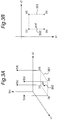
- the peak is predicted to be in area 301, but the peak point is not on a sampling point.
- weighted averaging is here applied to the four points around the position believed to be the peak, but an equivalent effect can be obtained using a number of points other than four.
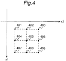
- Fig. 4 shows another case in which weighted averaging is applied to nine sampling points 401 - 409. While equation 16 obtains the weighted average of four points to obtain x0, the same concept applied in equation 16 is used to calculate the weighted average of the nine points 401 - 409 and obtain x0. Note that the reliability of the result is increased by further increasing the number of points referenced in the calculation.
- the motion vector quantity can be obtained structurally with fewer calculations.
- this motion vector detection apparatus comprises a subsampling circuit 1, a discrete Fourier transform circuit 2, a memory 3 storing the output of the discrete Fourier transform circuit 2, a divider 4, an inverse discrete Fourier transform circuit 5, and a first evaluation circuit 6 for detecting motion vectors from the output of the inverse discrete Fourier transform circuit 5 as in the first embodiment above.
- This second embodiment differs from the first in the insertion of a low pass filter 7 before the subsampling circuit 1.
- this motion vector detection apparatus is described below.
- the high frequency component of the input video signal 12 is first removed by the low pass filter 7.
- the input signal which has now been reduced to a low frequency component signal, is then input to the subsampling circuit 1.
- the low pass filter 7 operates to cut out the high frequency component so that there is no frequency reflection after subsampling in the next stage. Operation after the subsampling circuit 1 is the same as in the first embodiment above, and the end result is motion vector detection.
- the high frequency component of the image is lost by providing the low pass filter 7
- the high frequency component is normally used to reproduce image detail, and is not as important as the low frequency component when the overall image is moving.
- eliminating the high frequency component poses no problem because the objective is not image reproduction.
- motion vectors can be detected with greater accuracy in this embodiment than in the first embodiment.
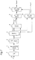
- this motion vector detection apparatus comprises a low pass filter 7, a subsampling circuit 1, a discrete Fourier transform circuit 2, a memory 3 storing the output of the discrete Fourier transform circuit 2, a divider 4, and an inverse discrete Fourier transform circuit 5 as in the second embodiment in Fig. 5 above.
- This third embodiment differs from the second in that the output of the divider 4 is input to an absolute value calculation circuit 8, and a second evaluation circuit 9 detecting the motion vectors from the outputs of the absolute value calculation circuit 8 and the inverse discrete Fourier transform circuit 5 is used in place of the first evaluation circuit.
- the input video signal 12 is input to the low pass filter 7, which passes only the low frequency component, and the subsampling circuit 1 then reduces the number of sampling points.
- the output of the subsampling circuit 1 is input to the discrete Fourier transform circuit 2, which converts the signal to frequency area data by a discrete Fourier transform operation.
- the memory 3 stores the output of the discrete Fourier transform circuit 2 temporarily and outputs the data from the previous input video frame.
- the divider 4 divides the output from the previous frame and the Fourier transform output of the current frame. Operation to this point is the same as in the second embodiment above.
- the output of the divider 4 is thus G( ⁇ )/F( ⁇ ).
- the output of the divider 4 is converted by a discrete inverse Fourier transform operation by the inverse discrete Fourier transform circuit 5, and is also input to the absolute value calculation circuit 8.
- the absolute value calculation circuit 8 obtains the absolute value of each ⁇ value, i.e., calculates
- the second evaluation circuit 9 therefore outputs the motion vectors based on the output from the inverse discrete Fourier transform circuit 5. Conversely, when most of the output values from the absolute value calculation circuit 8 are not 1, it is meaningless to detect the motion vectors, and even if there is some peak in the output from the inverse discrete Fourier transform circuit 5, the second evaluation circuit 9 operates to not output the motion vector.
- the absolute value calculation circuit 8 counts the number of input division results within the range 1 +/- ⁇ (where ⁇ is a positive value); when the total count exceeds a predetermined threshold value,
- the third embodiment of the invention knows based on the output from the absolute value calculation circuit 8 whether there is actually a motion vector, and the second evaluation circuit 9 therefore operates to not output a wrong evaluation result for false peaks accidentally output by the inverse discrete Fourier transform circuit 5.
- the absolute value calculation circuit 8 used in the third embodiment above uses the fact that
- 0 [19] for all ⁇ when the image is a still image or is moving in one direction. Therefore, if
- Fig. 7 is a block diagram of a motion vector detection apparatus in which a difference calculation circuit is used in place of the absolute value calculation circuit 8 of the third embodiment.
- this motion vector detection apparatus comprises a low pass filter 7, a subsampling circuit 1, a discrete Fourier transform circuit 2, a memory 3 storing the output of the discrete Fourier transform circuit 2, a divider 4, and an inverse discrete Fourier transform circuit 5 as in the third embodiment in Fig. 6 above.
- This embodiment differs from the third embodiment in that the absolute value calculation circuit 8 is replaced by a difference calculation circuit 10, which takes inputs from the memory 3 and the discrete Fourier transform circuit 2, and a third evaluation circuit 11 is used in place of the second evaluation circuit 9.
- This third evaluation circuit 11 operates on the outputs from the inverse discrete Fourier transform circuit 5 and the difference calculation circuit 10.
- the input video signal 12 is input to the low pass filter 7 for bandwidth limiting to prevent reflection at the next subsampling stage.
- the bandwidth limited data is input to the subsampling circuit for subsampling, and the discrete Fourier transform of the current frame and the discrete Fourier transform of the previous frame are divided by the divider 4 as in the second embodiment.
- the difference calculation circuit 10 obtains the absolute values of the temporarily stored output of the memory 3 and the output of the discrete Fourier transform circuit 2, and then obtains the difference of the absolute values. Specifically, the output of the difference calculation circuit 10 expresses the value
- the third evaluation circuit 11 adds the outputs of the difference calculation circuit 10 for all ⁇ . When the result is less than a predetermined threshold value,
- the screen information can be obtained and the motion vector detected by performing a difference calculation instead of the absolute value calculation of the third embodiment, and integrating the difference values for ⁇ .
- the third embodiment it is determined whether
- the quotient is not within the threshold value of 1 during evaluation of a given ⁇ , this number is not counted even when the quotient is offset only slightly from the threshold value in the third embodiment.
- the adverse effects of the third embodiment caused by a value coincidentally exceeding the threshold value or coincidentally less than the threshold value are avoided because the difference calculation results are integrated one at a time.
Landscapes
- Engineering & Computer Science (AREA)
- Physics & Mathematics (AREA)
- Mathematical Physics (AREA)
- Multimedia (AREA)
- Computer Vision & Pattern Recognition (AREA)
- General Physics & Mathematics (AREA)
- Theoretical Computer Science (AREA)
- Compression Or Coding Systems Of Tv Signals (AREA)
- Image Analysis (AREA)
- Color Television Systems (AREA)
Applications Claiming Priority (3)
| Application Number | Priority Date | Filing Date | Title |
|---|---|---|---|
| JP13347693A JPH06350997A (ja) | 1993-06-03 | 1993-06-03 | 動きベクトル検出装置 |
| JP133476/93 | 1993-06-03 | ||
| JP13347693 | 1993-06-03 |
Publications (3)
| Publication Number | Publication Date |
|---|---|
| EP0627696A2 true EP0627696A2 (fr) | 1994-12-07 |
| EP0627696A3 EP0627696A3 (fr) | 1996-04-17 |
| EP0627696B1 EP0627696B1 (fr) | 2001-04-11 |
Family
ID=15105675
Family Applications (1)
| Application Number | Title | Priority Date | Filing Date |
|---|---|---|---|
| EP19940108519 Expired - Lifetime EP0627696B1 (fr) | 1993-06-03 | 1994-06-03 | Appareil de détection de vecteurs de mouvement d'image |
Country Status (3)
| Country | Link |
|---|---|
| EP (1) | EP0627696B1 (fr) |
| JP (1) | JPH06350997A (fr) |
| DE (1) | DE69427050T2 (fr) |
Cited By (6)
| Publication number | Priority date | Publication date | Assignee | Title |
|---|---|---|---|---|
| WO1997004588A1 (fr) * | 1995-07-21 | 1997-02-06 | Innovision Limited | Traitement par correlation ameliore pour l'estimation du mouvement |
| WO1997023844A1 (fr) * | 1995-12-21 | 1997-07-03 | Philips Electronics N.V. | Attenuation directionnelle et adaptative de bruit |
| RU2243591C1 (ru) * | 2003-05-05 | 2004-12-27 | Федеральное государственное унитарное предприятие "Государственный научно-исследовательский институт авиационных систем" | Способ получения изображения объекта |
| CN103985140A (zh) * | 2014-05-22 | 2014-08-13 | 中国人民解放军国防科学技术大学 | 一种基于频域处理的抗噪运动目标检测方法 |
| CN104112283A (zh) * | 2014-07-30 | 2014-10-22 | 成都金本华科技股份有限公司 | 一种面向通用航空视频监视的动目标的快速测向系统及方法 |
| US10411716B2 (en) * | 2016-06-06 | 2019-09-10 | Richwave Technology Corp. | Subsampling motion detector for detecting motion of object under measurement |
Families Citing this family (1)
| Publication number | Priority date | Publication date | Assignee | Title |
|---|---|---|---|---|
| WO2009090735A1 (fr) * | 2008-01-16 | 2009-07-23 | Hitachi, Ltd. | Procédé et dispositif de détection de vecteur de mouvement, procédé de commande de panneau d'affichage plasma, et dispositif d'affichage plasma |
Citations (1)
| Publication number | Priority date | Publication date | Assignee | Title |
|---|---|---|---|---|
| EP0368747A1 (fr) | 1988-11-10 | 1990-05-16 | Thomson-Csf | Procédé d'estimation du mouvement d'au moins une cible dans une suite d'images, et dispositif pour la mise en oeuvre de ce procédé |
Family Cites Families (1)
| Publication number | Priority date | Publication date | Assignee | Title |
|---|---|---|---|---|
| US5111511A (en) * | 1988-06-24 | 1992-05-05 | Matsushita Electric Industrial Co., Ltd. | Image motion vector detecting apparatus |
-
1993
- 1993-06-03 JP JP13347693A patent/JPH06350997A/ja active Pending
-
1994
- 1994-06-03 DE DE69427050T patent/DE69427050T2/de not_active Expired - Fee Related
- 1994-06-03 EP EP19940108519 patent/EP0627696B1/fr not_active Expired - Lifetime
Patent Citations (1)
| Publication number | Priority date | Publication date | Assignee | Title |
|---|---|---|---|---|
| EP0368747A1 (fr) | 1988-11-10 | 1990-05-16 | Thomson-Csf | Procédé d'estimation du mouvement d'au moins une cible dans une suite d'images, et dispositif pour la mise en oeuvre de ce procédé |
Cited By (10)
| Publication number | Priority date | Publication date | Assignee | Title |
|---|---|---|---|---|
| WO1997004588A1 (fr) * | 1995-07-21 | 1997-02-06 | Innovision Limited | Traitement par correlation ameliore pour l'estimation du mouvement |
| US6057892A (en) * | 1995-07-21 | 2000-05-02 | Innovision, Plc. | Correlation processing for motion estimation |
| WO1997023844A1 (fr) * | 1995-12-21 | 1997-07-03 | Philips Electronics N.V. | Attenuation directionnelle et adaptative de bruit |
| US6049623A (en) * | 1995-12-21 | 2000-04-11 | U.S. Philips Corporation | Directional adaptive noise reduction |
| RU2243591C1 (ru) * | 2003-05-05 | 2004-12-27 | Федеральное государственное унитарное предприятие "Государственный научно-исследовательский институт авиационных систем" | Способ получения изображения объекта |
| CN103985140A (zh) * | 2014-05-22 | 2014-08-13 | 中国人民解放军国防科学技术大学 | 一种基于频域处理的抗噪运动目标检测方法 |
| CN103985140B (zh) * | 2014-05-22 | 2015-06-03 | 中国人民解放军国防科学技术大学 | 一种基于频域处理的抗噪运动目标检测方法 |
| CN104112283A (zh) * | 2014-07-30 | 2014-10-22 | 成都金本华科技股份有限公司 | 一种面向通用航空视频监视的动目标的快速测向系统及方法 |
| US10411716B2 (en) * | 2016-06-06 | 2019-09-10 | Richwave Technology Corp. | Subsampling motion detector for detecting motion of object under measurement |
| US10530369B2 (en) | 2016-06-06 | 2020-01-07 | Richwave Technology Corp. | Subsampling motion detector for detecting motion of object under measurement |
Also Published As
| Publication number | Publication date |
|---|---|
| JPH06350997A (ja) | 1994-12-22 |
| EP0627696B1 (fr) | 2001-04-11 |
| DE69427050T2 (de) | 2001-08-02 |
| EP0627696A3 (fr) | 1996-04-17 |
| DE69427050D1 (de) | 2001-05-17 |
Similar Documents
| Publication | Publication Date | Title |
|---|---|---|
| Lewis | Fast template matching | |
| US6252974B1 (en) | Method and apparatus for depth modelling and providing depth information of moving objects | |
| US5369599A (en) | Signal metric estimator | |
| EP0686942B1 (fr) | Méthode de concordance et mesure de disparité stéréo | |
| EP1153365B1 (fr) | Procede et appareil d'extraction de texture d'image | |
| EP1233374B1 (fr) | Dispositif et procédé d'extraction d'objets par mise en correspondence des charactéristiques dans des régions d'images segmentées | |
| US6192161B1 (en) | Method and apparatus for adaptive filter tap selection according to a class | |
| US9179092B2 (en) | System and method producing high definition video from low definition video | |
| EP1400924B1 (fr) | Appareil pour créer une image pseudo-tridimensionelle | |
| US6456660B1 (en) | Device and method of detecting motion vectors | |
| US20090316990A1 (en) | Object recognition device, object recognition method, program for object recognition method, and recording medium having recorded thereon program for object recognition method | |
| KR20010033552A (ko) | 비디오 시퀀스의 변환 검출 | |
| JPH01500238A (ja) | テレビジョン画像における運動の測定方法及び装置 | |
| EP0806866A2 (fr) | Dispositif d'évaluation et méthode utilisable dans un appareil de détection de vecteurs de mouvement | |
| KR950023051A (ko) | 영상 시퀀스에서의 장면 변화 검출 방법 및 장치 | |
| US20090136092A1 (en) | Object boundary accurate motion detection using hierarchical block splitting and motion segmentation | |
| JPH11509386A (ja) | 動作推定の相関処理の改良 | |
| KR20190080737A (ko) | 영상을 처리하는 방법, 장치 및 컴퓨터 프로그램 제품 | |
| EP0627696A2 (fr) | Appareil de détection de vecteurs de mouvement d'image | |
| EP1222614B1 (fr) | Procede et appareil permettant de choisir des valeurs de classe de facon adaptative en fonction d'une classification multiple | |
| Ting et al. | Edge preserving interpolation of digital images using fuzzy inference | |
| Vernon | Decoupling Fourier components of dynamic image sequences: a theory of signal separation, image segmentation, and optical flow estimation | |
| US6307979B1 (en) | Classified adaptive error recovery method and apparatus | |
| Yang et al. | Motion blur detecting by support vector machine | |
| US7006569B1 (en) | Digital video processing method and apparatus thereof |
Legal Events
| Date | Code | Title | Description |
|---|---|---|---|
| PUAI | Public reference made under article 153(3) epc to a published international application that has entered the european phase |
Free format text: ORIGINAL CODE: 0009012 |
|
| 17P | Request for examination filed |
Effective date: 19940603 |
|
| AK | Designated contracting states |
Kind code of ref document: A2 Designated state(s): DE FR GB NL |
|
| PUAL | Search report despatched |
Free format text: ORIGINAL CODE: 0009013 |
|
| AK | Designated contracting states |
Kind code of ref document: A3 Designated state(s): DE FR GB NL |
|
| 17Q | First examination report despatched |
Effective date: 19990330 |
|
| RIC1 | Information provided on ipc code assigned before grant |
Free format text: 7G 06T 7/20 A |
|
| GRAG | Despatch of communication of intention to grant |
Free format text: ORIGINAL CODE: EPIDOS AGRA |
|
| GRAG | Despatch of communication of intention to grant |
Free format text: ORIGINAL CODE: EPIDOS AGRA |
|
| GRAH | Despatch of communication of intention to grant a patent |
Free format text: ORIGINAL CODE: EPIDOS IGRA |
|
| GRAH | Despatch of communication of intention to grant a patent |
Free format text: ORIGINAL CODE: EPIDOS IGRA |
|
| GRAA | (expected) grant |
Free format text: ORIGINAL CODE: 0009210 |
|
| AK | Designated contracting states |
Kind code of ref document: B1 Designated state(s): DE FR GB NL |
|
| PG25 | Lapsed in a contracting state [announced via postgrant information from national office to epo] |
Ref country code: NL Free format text: LAPSE BECAUSE OF FAILURE TO SUBMIT A TRANSLATION OF THE DESCRIPTION OR TO PAY THE FEE WITHIN THE PRESCRIBED TIME-LIMIT Effective date: 20010411 |
|
| REF | Corresponds to: |
Ref document number: 69427050 Country of ref document: DE Date of ref document: 20010517 |
|
| ET | Fr: translation filed | ||
| NLV1 | Nl: lapsed or annulled due to failure to fulfill the requirements of art. 29p and 29m of the patents act | ||
| REG | Reference to a national code |
Ref country code: GB Ref legal event code: IF02 |
|
| PLBE | No opposition filed within time limit |
Free format text: ORIGINAL CODE: 0009261 |
|
| STAA | Information on the status of an ep patent application or granted ep patent |
Free format text: STATUS: NO OPPOSITION FILED WITHIN TIME LIMIT |
|
| 26N | No opposition filed | ||
| PGFP | Annual fee paid to national office [announced via postgrant information from national office to epo] |
Ref country code: DE Payment date: 20070531 Year of fee payment: 14 |
|
| PGFP | Annual fee paid to national office [announced via postgrant information from national office to epo] |
Ref country code: GB Payment date: 20070530 Year of fee payment: 14 |
|
| PGFP | Annual fee paid to national office [announced via postgrant information from national office to epo] |
Ref country code: FR Payment date: 20070608 Year of fee payment: 14 |
|
| GBPC | Gb: european patent ceased through non-payment of renewal fee |
Effective date: 20080603 |
|
| REG | Reference to a national code |
Ref country code: FR Ref legal event code: ST Effective date: 20090228 |
|
| PG25 | Lapsed in a contracting state [announced via postgrant information from national office to epo] |
Ref country code: DE Free format text: LAPSE BECAUSE OF NON-PAYMENT OF DUE FEES Effective date: 20090101 |
|
| PG25 | Lapsed in a contracting state [announced via postgrant information from national office to epo] |
Ref country code: GB Free format text: LAPSE BECAUSE OF NON-PAYMENT OF DUE FEES Effective date: 20080603 |
|
| PG25 | Lapsed in a contracting state [announced via postgrant information from national office to epo] |
Ref country code: FR Free format text: LAPSE BECAUSE OF NON-PAYMENT OF DUE FEES Effective date: 20080630 |