EP0627751A1 - Lastschalter mit doppelter Lichtbogenverlängerung zum Auslösen von Stromen mit grosse Gleichstromkomponente - Google Patents
Lastschalter mit doppelter Lichtbogenverlängerung zum Auslösen von Stromen mit grosse Gleichstromkomponente Download PDFInfo
- Publication number
- EP0627751A1 EP0627751A1 EP94401207A EP94401207A EP0627751A1 EP 0627751 A1 EP0627751 A1 EP 0627751A1 EP 94401207 A EP94401207 A EP 94401207A EP 94401207 A EP94401207 A EP 94401207A EP 0627751 A1 EP0627751 A1 EP 0627751A1
- Authority
- EP
- European Patent Office
- Prior art keywords
- contact
- arc
- current
- tube
- fixed
- Prior art date
- Legal status (The legal status is an assumption and is not a legal conclusion. Google has not performed a legal analysis and makes no representation as to the accuracy of the status listed.)
- Withdrawn
Links
- 238000007664 blowing Methods 0.000 claims abstract description 13
- 238000009413 insulation Methods 0.000 claims abstract 2
- 239000002184 metal Substances 0.000 claims description 9
- 239000011324 bead Substances 0.000 claims description 8
- 230000000694 effects Effects 0.000 claims description 6
- 238000010891 electric arc Methods 0.000 claims description 3
- 229910001092 metal group alloy Inorganic materials 0.000 claims description 3
- 229910018503 SF6 Inorganic materials 0.000 description 5
- SFZCNBIFKDRMGX-UHFFFAOYSA-N sulfur hexafluoride Chemical compound FS(F)(F)(F)(F)F SFZCNBIFKDRMGX-UHFFFAOYSA-N 0.000 description 5
- 229960000909 sulfur hexafluoride Drugs 0.000 description 5
- 239000007789 gas Substances 0.000 description 4
- IJGRMHOSHXDMSA-UHFFFAOYSA-N Atomic nitrogen Chemical compound N#N IJGRMHOSHXDMSA-UHFFFAOYSA-N 0.000 description 2
- 239000004809 Teflon Substances 0.000 description 2
- 229920006362 Teflon® Polymers 0.000 description 2
- 230000007423 decrease Effects 0.000 description 2
- 239000011810 insulating material Substances 0.000 description 2
- 230000006978 adaptation Effects 0.000 description 1
- 229910045601 alloy Inorganic materials 0.000 description 1
- 239000000956 alloy Substances 0.000 description 1
- 239000000919 ceramic Substances 0.000 description 1
- 230000003111 delayed effect Effects 0.000 description 1
- 238000010586 diagram Methods 0.000 description 1
- 230000008034 disappearance Effects 0.000 description 1
- 230000004907 flux Effects 0.000 description 1
- 230000006698 induction Effects 0.000 description 1
- 230000008018 melting Effects 0.000 description 1
- 238000002844 melting Methods 0.000 description 1
- 230000004048 modification Effects 0.000 description 1
- 238000012986 modification Methods 0.000 description 1
- 229910052757 nitrogen Inorganic materials 0.000 description 1
- 238000000926 separation method Methods 0.000 description 1
- WFKWXMTUELFFGS-UHFFFAOYSA-N tungsten Chemical compound [W] WFKWXMTUELFFGS-UHFFFAOYSA-N 0.000 description 1
Images


Classifications
-
- H—ELECTRICITY
- H01—ELECTRIC ELEMENTS
- H01H—ELECTRIC SWITCHES; RELAYS; SELECTORS; EMERGENCY PROTECTIVE DEVICES
- H01H33/00—High-tension or heavy-current switches with arc-extinguishing or arc-preventing means
- H01H33/02—Details
- H01H33/04—Means for extinguishing or preventing arc between current-carrying parts
- H01H33/18—Means for extinguishing or preventing arc between current-carrying parts using blow-out magnet
-
- H—ELECTRICITY
- H01—ELECTRIC ELEMENTS
- H01H—ELECTRIC SWITCHES; RELAYS; SELECTORS; EMERGENCY PROTECTIVE DEVICES
- H01H33/00—High-tension or heavy-current switches with arc-extinguishing or arc-preventing means
- H01H33/006—High-tension or heavy-current switches with arc-extinguishing or arc-preventing means adapted for interrupting fault currents with delayed zero crossings
-
- H—ELECTRICITY
- H01—ELECTRIC ELEMENTS
- H01H—ELECTRIC SWITCHES; RELAYS; SELECTORS; EMERGENCY PROTECTIVE DEVICES
- H01H33/00—High-tension or heavy-current switches with arc-extinguishing or arc-preventing means
- H01H33/70—Switches with separate means for directing, obtaining, or increasing flow of arc-extinguishing fluid
- H01H33/88—Switches with separate means for directing, obtaining, or increasing flow of arc-extinguishing fluid the flow of arc-extinguishing fluid being produced or increased by movement of pistons or other pressure-producing parts
- H01H33/90—Switches with separate means for directing, obtaining, or increasing flow of arc-extinguishing fluid the flow of arc-extinguishing fluid being produced or increased by movement of pistons or other pressure-producing parts this movement being effected by or in conjunction with the contact-operating mechanism
- H01H33/91—Switches with separate means for directing, obtaining, or increasing flow of arc-extinguishing fluid the flow of arc-extinguishing fluid being produced or increased by movement of pistons or other pressure-producing parts this movement being effected by or in conjunction with the contact-operating mechanism the arc-extinguishing fluid being air or gas
Definitions
- the present invention relates to the breaking of currents with a large DC component, which is encountered, for example, in high-voltage alternating networks with series compensation, when certain types of faults appear.
- the presence of the DC component can cause the current to pass through zero for several periods. It is therefore difficult to cut off the power using conventional sulfur hexafluoride (SF6) circuit breakers.
- SF6 sulfur hexafluoride
- An object of the present invention is to provide a circuit breaker capable of creating a high arc voltage, using the SF6 circuit breakers existing on the market, with a minor modification and at low cost;
- the basic idea is to configure the arcing contacts so that the current crosses them, in at least part of their length, in the opposite direction to the arcing current. In this way, on each of these contacts, a current loop is created, which, under Lenz's law, tends to enlarge, so that the roots of the arc are pushed away from the ends of the contacts. arc.
- the arc is thus doubly elongated which, as explained above, promotes the disappearance of the DC component of the current.
- the invention thus relates to a circuit breaker as described in the claims.
- the oscillogram of FIG. 1 shows the fault current with the delayed current passing through zero.
- the arc To advance the zero crossing of the current, the arc must therefore be extended to the maximum possible as soon as the arcing contacts are separated.
- Figure 2 is a schematic view in axial section of a breaking chamber of a pole of a conventional circuit breaker, shown in the tripped position. It comprises an envelope 1, made of insulating material such as ceramic, closed by two metal flanges 2 and 3 carrying sockets 2A and 3A. The volume 4 thus delimited is filled with a gas with good dielectric properties such as sulfur hexafluoride SF6 or nitrogen, under a pressure of a few hectopascals.
- a gas with good dielectric properties such as sulfur hexafluoride SF6 or nitrogen, under a pressure of a few hectopascals.
- a fixed assembly Inside the envelope are arranged a fixed assembly and a movable assembly.
- the fixed assembly comprises metal arms 5 mechanically and electrically connected to the flange 2 and supporting a contact 6 for the passage of the permanent current and an arcing contact 7.
- Contact 6 is a tube; the contact 7 is also tubular and will be described in detail with reference to FIG. 3.
- the mobile assembly comprises a cylinder 9, one end of which carries a metal crown 10; the cylinder is connected to an insulating rod 11 which passes tightly through the flange 3 and which is connected to a control not shown.
- the ring 10 carries contact fingers 12 for the passage of the permanent current and which cooperate, when the circuit breaker is closed, with the tube 6.
- the fingers 12 are protected by a corona hood 12A fixed to the cylinder 9.
- the crown 10 carries a blowing nozzle 17 preferably made of insulating material.
- the piston 18, the crown 10 and the cylinder 9 define a blowing volume V.
- the crown 10 carries holes 10A to allow the gas of volume V, compressed during an opening operation of the circuit breaker, to escape through the nozzle to blow the arc.
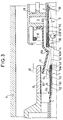
- Figure 3 shows the specific constitution of the arcing contacts, allowing the arc to be extended twice.
- the fixed arcing contact generally designated by the reference 7, comprises two coaxial tubular metal portions 50 and 51, separated by an insulating layer 52, for example made of Teflon.
- the portions 50 and 51 are joined at their end by a metal tip 49 made of an alloy resistant to the effects of the electric arc, for example based on tunstene (wolfram).
- the tubular portion 51 is intended to cooperate with the fingers 14 of the movable assembly. It is terminated at the end opposite to the end piece by an annular bead 54.
- the tubular portion 50 is coated internally, over a certain length, from the end piece 49, by an insulating layer 53, for example made of teflon.
- the tube carrying the fingers of the movable arcing contact consists of two coaxial metal portions 57 and 60, isolated from each other by an insulating layer 59, and joined to a end by a tip 56 made of metal alloy resistant to the effects of electric arc.
- the layer 57 is terminated, at its end opposite the end piece 56, by an annular bead 58.
- the main fingers 12 are supported on the metal tube 6
- the arcing fingers 14 are supported on the metal tube 51.
- the arc moves from the fingers 14 to the nozzle 56, especially if the current is in the downward phase A of current reduction (see Fig. 1).
- the current in the arc is of opposite direction to the current in the zone 57A of the tube 57.
- the loop effect (law of the maximum induction flux or Lenz's law) tends to move the root of the arc 62A along the interior surface of the tube 57 to the bead 58.
- the blowing of the gas pushes the root of the arc 62B of the nozzle 49 towards the external end region 51A of the tube 51.
- the current in 51A is of direction opposite that of arc 62B; the loop effect pushes the root of the arc along the outer surface of the tube 51 to the bead 54, especially if the current is in the downward phase A or in the downward phase B.
- This current has an intensity of several millirs of amperes.
- the insulating layer 53 prevents the arc from catching on the interior surface of the tube 50.
- an insulating layer 55 is placed on the interior surface of this tube.
- the double elongation of the arc, on the fixed side and on the movable side, makes it possible to obtain a large arc voltage which, by its intrinsic resistance, makes it easier for the DC component to decrease, to force a zero crossing, either by t1, or in t2, depending on the value of the current and the duration of the arc.
- the invention makes it possible, by means of an inexpensive adaptation of existing circuit breakers, to obtain a device perfectly suited to breaking currents with a large DC component.
Landscapes
- Circuit Breakers (AREA)
Applications Claiming Priority (2)
| Application Number | Priority Date | Filing Date | Title |
|---|---|---|---|
| FR9306661A FR2706073B1 (fr) | 1993-06-03 | 1993-06-03 | Disjoncteur à double allongement d'arc pour la coupure des courants à grande composante continue. |
| FR9306661 | 1993-06-03 |
Publications (1)
| Publication Number | Publication Date |
|---|---|
| EP0627751A1 true EP0627751A1 (de) | 1994-12-07 |
Family
ID=9447727
Family Applications (1)
| Application Number | Title | Priority Date | Filing Date |
|---|---|---|---|
| EP94401207A Withdrawn EP0627751A1 (de) | 1993-06-03 | 1994-06-01 | Lastschalter mit doppelter Lichtbogenverlängerung zum Auslösen von Stromen mit grosse Gleichstromkomponente |
Country Status (2)
| Country | Link |
|---|---|
| EP (1) | EP0627751A1 (de) |
| FR (1) | FR2706073B1 (de) |
Citations (4)
| Publication number | Priority date | Publication date | Assignee | Title |
|---|---|---|---|---|
| DE7617505U1 (de) * | 1976-05-28 | 1980-02-07 | Siemens Ag, 1000 Berlin Und 8000 Muenchen | Kontaktanordnung fur Druckgasschalter |
| EP0039523A1 (de) * | 1980-05-07 | 1981-11-11 | BBC Aktiengesellschaft Brown, Boveri & Cie. | Hochspannungsleistungsschalter |
| DE9016830U1 (de) * | 1990-12-10 | 1991-02-28 | Siemens AG, 8000 München | Hochspannungs-Leistungsschalter |
| FR2681724A1 (fr) * | 1991-09-24 | 1993-03-26 | Alsthom Gec | Disjoncteur haute tension a grande tension d'arc. |
-
1993
- 1993-06-03 FR FR9306661A patent/FR2706073B1/fr not_active Expired - Fee Related
-
1994
- 1994-06-01 EP EP94401207A patent/EP0627751A1/de not_active Withdrawn
Patent Citations (4)
| Publication number | Priority date | Publication date | Assignee | Title |
|---|---|---|---|---|
| DE7617505U1 (de) * | 1976-05-28 | 1980-02-07 | Siemens Ag, 1000 Berlin Und 8000 Muenchen | Kontaktanordnung fur Druckgasschalter |
| EP0039523A1 (de) * | 1980-05-07 | 1981-11-11 | BBC Aktiengesellschaft Brown, Boveri & Cie. | Hochspannungsleistungsschalter |
| DE9016830U1 (de) * | 1990-12-10 | 1991-02-28 | Siemens AG, 8000 München | Hochspannungs-Leistungsschalter |
| FR2681724A1 (fr) * | 1991-09-24 | 1993-03-26 | Alsthom Gec | Disjoncteur haute tension a grande tension d'arc. |
Also Published As
| Publication number | Publication date |
|---|---|
| FR2706073B1 (fr) | 1995-07-07 |
| FR2706073A1 (fr) | 1994-12-09 |
Similar Documents
| Publication | Publication Date | Title |
|---|---|---|
| EP0577530B1 (de) | Selbst-gebläsener Schalter oder Lastschalter | |
| CA2037119C (fr) | Disjoncteur a coupure assistee par varistance | |
| CA1176289A (fr) | Disjoncteur a gaz comprime muni de resistances d'ouverture et de fermeture | |
| EP0441292A1 (de) | Mittelspannungsschalter mit Selbstbeblasung | |
| EP0461629A1 (de) | Leistungsschalter mit eingebautem Varistor | |
| CA2206950C (fr) | Disjoncteur a haute tension avec insertion de resistance a la fermeture. | |
| EP0240397A1 (de) | Selbstbeblasender elektrischer Lastschalter mit rotierendem Lichtbogen | |
| EP0759629B1 (de) | Lastschalter mit Einschaltwiderstand und Einfügungsvorrichtung | |
| CA2017127C (fr) | Disjoncteur a moyenne tension a courant nominal eleve | |
| EP0785562B1 (de) | Lastschalter mit Kontakten mit Doppelbewegung | |
| EP0536039A1 (de) | Ultra-Hochspannungsschalter | |
| EP0627751A1 (de) | Lastschalter mit doppelter Lichtbogenverlängerung zum Auslösen von Stromen mit grosse Gleichstromkomponente | |
| CA2041234C (fr) | Disjoncteur a haute tension a arc serie | |
| EP0450567B1 (de) | Hoch- oder Mittelspannungs-Schalter mit aufeinanderstossenden Lichtbogenkontakten | |
| FR2679375A1 (fr) | Contact pour disjoncteur. | |
| FR2711269A1 (fr) | Disjoncteur à haute tension capable de couper des courants de défaut à passage par zéro retardé. | |
| FR2944911A1 (fr) | Interrupteur-sectionneur electrique rotatif de moyenne et haute tension a resistance | |
| FR2683937A1 (fr) | Disjoncteur hybride pour la coupure des courants a grande composante continue. | |
| FR2711013A1 (fr) | Disjoncteur à grande tension d'arc. | |
| FR2658949A1 (fr) | Disjoncteur a coupure assistee par varistance. | |
| EP0823721B1 (de) | Selbstbeblasender elektrischer Lastschalter mit rotierendem Lichtbogen | |
| FR2709019A1 (fr) | Disjoncteur à insertion de résistance d'ouverture par arcs multiples. | |
| EP0398116B1 (de) | Mittelspannungsschalter mit Selbstbeblasung | |
| FR2657459A1 (fr) | Disjoncteur a haute tension a resistance de fermeture. | |
| FR2737937A1 (fr) | Disjoncteur a double mouvement avec resistance de fermeture |
Legal Events
| Date | Code | Title | Description |
|---|---|---|---|
| PUAI | Public reference made under article 153(3) epc to a published international application that has entered the european phase |
Free format text: ORIGINAL CODE: 0009012 |
|
| AK | Designated contracting states |
Kind code of ref document: A1 Designated state(s): AT CH DE ES FR GB IT LI SE |
|
| 17P | Request for examination filed |
Effective date: 19950513 |
|
| 17Q | First examination report despatched |
Effective date: 19960325 |
|
| GRAG | Despatch of communication of intention to grant |
Free format text: ORIGINAL CODE: EPIDOS AGRA |
|
| GRAH | Despatch of communication of intention to grant a patent |
Free format text: ORIGINAL CODE: EPIDOS IGRA |
|
| STAA | Information on the status of an ep patent application or granted ep patent |
Free format text: STATUS: THE APPLICATION IS DEEMED TO BE WITHDRAWN |
|
| 18D | Application deemed to be withdrawn |
Effective date: 19970118 |