EP0627773B1 - Fil supraconducteur d'oxyde et appareil supraconducteur utilisant ce fil - Google Patents
Fil supraconducteur d'oxyde et appareil supraconducteur utilisant ce fil Download PDFInfo
- Publication number
- EP0627773B1 EP0627773B1 EP94107489A EP94107489A EP0627773B1 EP 0627773 B1 EP0627773 B1 EP 0627773B1 EP 94107489 A EP94107489 A EP 94107489A EP 94107489 A EP94107489 A EP 94107489A EP 0627773 B1 EP0627773 B1 EP 0627773B1
- Authority
- EP
- European Patent Office
- Prior art keywords
- superconducting
- wire
- oxides
- oxide
- conductor
- Prior art date
- Legal status (The legal status is an assumption and is not a legal conclusion. Google has not performed a legal analysis and makes no representation as to the accuracy of the status listed.)
- Revoked
Links
- 239000000463 material Substances 0.000 claims description 104
- 239000002887 superconductor Substances 0.000 claims description 57
- 239000004020 conductor Substances 0.000 claims description 55
- BQCADISMDOOEFD-UHFFFAOYSA-N Silver Chemical compound [Ag] BQCADISMDOOEFD-UHFFFAOYSA-N 0.000 claims description 49
- 229910052709 silver Inorganic materials 0.000 claims description 46
- 239000004332 silver Substances 0.000 claims description 46
- 239000002245 particle Substances 0.000 claims description 20
- 239000002131 composite material Substances 0.000 claims description 18
- PNEYBMLMFCGWSK-UHFFFAOYSA-N Alumina Chemical class [O-2].[O-2].[O-2].[Al+3].[Al+3] PNEYBMLMFCGWSK-UHFFFAOYSA-N 0.000 claims description 12
- 229910001316 Ag alloy Inorganic materials 0.000 claims description 11
- RVTZCBVAJQQJTK-UHFFFAOYSA-N oxygen(2-);zirconium(4+) Chemical class [O-2].[O-2].[Zr+4] RVTZCBVAJQQJTK-UHFFFAOYSA-N 0.000 claims description 9
- 229910001928 zirconium oxide Inorganic materials 0.000 claims description 9
- 235000012245 magnesium oxide Nutrition 0.000 claims description 5
- AXZKOIWUVFPNLO-UHFFFAOYSA-N magnesium;oxygen(2-) Chemical class [O-2].[Mg+2] AXZKOIWUVFPNLO-UHFFFAOYSA-N 0.000 claims description 5
- SOQBVABWOPYFQZ-UHFFFAOYSA-N oxygen(2-);titanium(4+) Chemical class [O-2].[O-2].[Ti+4] SOQBVABWOPYFQZ-UHFFFAOYSA-N 0.000 claims description 4
- RUDFQVOCFDJEEF-UHFFFAOYSA-N oxygen(2-);yttrium(3+) Chemical class [O-2].[O-2].[O-2].[Y+3].[Y+3] RUDFQVOCFDJEEF-UHFFFAOYSA-N 0.000 claims description 4
- OGIDPMRJRNCKJF-UHFFFAOYSA-N titanium oxide Inorganic materials [Ti]=O OGIDPMRJRNCKJF-UHFFFAOYSA-N 0.000 claims description 4
- 238000004804 winding Methods 0.000 claims description 4
- 229910000765 intermetallic Inorganic materials 0.000 claims description 3
- 229910052751 metal Inorganic materials 0.000 claims description 3
- 238000004146 energy storage Methods 0.000 claims description 2
- 239000002184 metal Substances 0.000 claims description 2
- 229910044991 metal oxide Inorganic materials 0.000 claims 6
- 150000004706 metal oxides Chemical class 0.000 claims 5
- 238000002844 melting Methods 0.000 claims 2
- 230000008018 melting Effects 0.000 claims 2
- 238000001816 cooling Methods 0.000 claims 1
- 239000010949 copper Substances 0.000 description 49
- 238000000034 method Methods 0.000 description 39
- 239000000843 powder Substances 0.000 description 30
- 238000012360 testing method Methods 0.000 description 25
- IJGRMHOSHXDMSA-UHFFFAOYSA-N Atomic nitrogen Chemical compound N#N IJGRMHOSHXDMSA-UHFFFAOYSA-N 0.000 description 20
- 239000002994 raw material Substances 0.000 description 20
- 239000007788 liquid Substances 0.000 description 15
- PCHJSUWPFVWCPO-UHFFFAOYSA-N gold Chemical compound [Au] PCHJSUWPFVWCPO-UHFFFAOYSA-N 0.000 description 12
- 229910052737 gold Inorganic materials 0.000 description 12
- 239000010931 gold Substances 0.000 description 12
- 238000010438 heat treatment Methods 0.000 description 12
- 239000000203 mixture Substances 0.000 description 11
- 229910052757 nitrogen Inorganic materials 0.000 description 10
- 238000003825 pressing Methods 0.000 description 10
- 239000001307 helium Substances 0.000 description 8
- 229910052734 helium Inorganic materials 0.000 description 8
- SWQJXJOGLNCZEY-UHFFFAOYSA-N helium atom Chemical compound [He] SWQJXJOGLNCZEY-UHFFFAOYSA-N 0.000 description 8
- 238000004519 manufacturing process Methods 0.000 description 8
- ODINCKMPIJJUCX-UHFFFAOYSA-N Calcium oxide Chemical compound [Ca]=O ODINCKMPIJJUCX-UHFFFAOYSA-N 0.000 description 6
- 235000012255 calcium oxide Nutrition 0.000 description 6
- 239000000292 calcium oxide Substances 0.000 description 6
- 150000001768 cations Chemical class 0.000 description 6
- RYGMFSIKBFXOCR-UHFFFAOYSA-N Copper Chemical compound [Cu] RYGMFSIKBFXOCR-UHFFFAOYSA-N 0.000 description 5
- 229910052802 copper Inorganic materials 0.000 description 5
- 239000013078 crystal Substances 0.000 description 5
- 239000002243 precursor Substances 0.000 description 5
- 239000000126 substance Substances 0.000 description 5
- 229910002480 Cu-O Inorganic materials 0.000 description 4
- 239000000654 additive Substances 0.000 description 4
- 230000000996 additive effect Effects 0.000 description 4
- 239000000956 alloy Substances 0.000 description 4
- QVQLCTNNEUAWMS-UHFFFAOYSA-N barium oxide Chemical compound [Ba]=O QVQLCTNNEUAWMS-UHFFFAOYSA-N 0.000 description 4
- 239000011248 coating agent Substances 0.000 description 4
- 238000000576 coating method Methods 0.000 description 4
- 238000005551 mechanical alloying Methods 0.000 description 4
- 238000005096 rolling process Methods 0.000 description 4
- MYMOFIZGZYHOMD-UHFFFAOYSA-N Dioxygen Chemical compound O=O MYMOFIZGZYHOMD-UHFFFAOYSA-N 0.000 description 3
- 229910045601 alloy Inorganic materials 0.000 description 3
- QVGXLLKOCUKJST-UHFFFAOYSA-N atomic oxygen Chemical compound [O] QVGXLLKOCUKJST-UHFFFAOYSA-N 0.000 description 3
- 150000001875 compounds Chemical class 0.000 description 3
- 239000002826 coolant Substances 0.000 description 3
- 238000013461 design Methods 0.000 description 3
- 238000011161 development Methods 0.000 description 3
- 238000002149 energy-dispersive X-ray emission spectroscopy Methods 0.000 description 3
- 239000007789 gas Substances 0.000 description 3
- 238000005259 measurement Methods 0.000 description 3
- 239000001301 oxygen Substances 0.000 description 3
- 229910052760 oxygen Inorganic materials 0.000 description 3
- 239000000523 sample Substances 0.000 description 3
- 238000005245 sintering Methods 0.000 description 3
- 241000907788 Cordia gerascanthus Species 0.000 description 2
- 229920002430 Fibre-reinforced plastic Polymers 0.000 description 2
- MUBZPKHOEPUJKR-UHFFFAOYSA-N Oxalic acid Chemical compound OC(=O)C(O)=O MUBZPKHOEPUJKR-UHFFFAOYSA-N 0.000 description 2
- 238000002441 X-ray diffraction Methods 0.000 description 2
- 238000004458 analytical method Methods 0.000 description 2
- 238000001354 calcination Methods 0.000 description 2
- 238000005253 cladding Methods 0.000 description 2
- 238000000975 co-precipitation Methods 0.000 description 2
- 230000003247 decreasing effect Effects 0.000 description 2
- 238000005516 engineering process Methods 0.000 description 2
- 239000011151 fibre-reinforced plastic Substances 0.000 description 2
- 239000011810 insulating material Substances 0.000 description 2
- 239000011812 mixed powder Substances 0.000 description 2
- 230000003647 oxidation Effects 0.000 description 2
- 238000007254 oxidation reaction Methods 0.000 description 2
- WKMKTIVRRLOHAJ-UHFFFAOYSA-N oxygen(2-);thallium(1+) Chemical compound [O-2].[Tl+].[Tl+] WKMKTIVRRLOHAJ-UHFFFAOYSA-N 0.000 description 2
- 230000000149 penetrating effect Effects 0.000 description 2
- 238000000634 powder X-ray diffraction Methods 0.000 description 2
- 239000011802 pulverized particle Substances 0.000 description 2
- 229910052761 rare earth metal Inorganic materials 0.000 description 2
- -1 strontia Chemical compound 0.000 description 2
- VEALVRVVWBQVSL-UHFFFAOYSA-N strontium titanate Chemical compound [Sr+2].[O-][Ti]([O-])=O VEALVRVVWBQVSL-UHFFFAOYSA-N 0.000 description 2
- 229910003438 thallium oxide Inorganic materials 0.000 description 2
- 239000010936 titanium Substances 0.000 description 2
- ZOKXTWBITQBERF-UHFFFAOYSA-N Molybdenum Chemical compound [Mo] ZOKXTWBITQBERF-UHFFFAOYSA-N 0.000 description 1
- 238000005275 alloying Methods 0.000 description 1
- 230000005540 biological transmission Effects 0.000 description 1
- 239000003518 caustics Substances 0.000 description 1
- IYRDVAUFQZOLSB-UHFFFAOYSA-N copper iron Chemical group [Fe].[Cu] IYRDVAUFQZOLSB-UHFFFAOYSA-N 0.000 description 1
- 238000000151 deposition Methods 0.000 description 1
- 239000006185 dispersion Substances 0.000 description 1
- 238000007606 doctor blade method Methods 0.000 description 1
- 230000020169 heat generation Effects 0.000 description 1
- 239000007769 metal material Substances 0.000 description 1
- 229910052750 molybdenum Inorganic materials 0.000 description 1
- 239000011733 molybdenum Substances 0.000 description 1
- 229910000476 molybdenum oxide Inorganic materials 0.000 description 1
- PQQKPALAQIIWST-UHFFFAOYSA-N oxomolybdenum Chemical compound [Mo]=O PQQKPALAQIIWST-UHFFFAOYSA-N 0.000 description 1
- 238000007750 plasma spraying Methods 0.000 description 1
- 238000010791 quenching Methods 0.000 description 1
- 230000000171 quenching effect Effects 0.000 description 1
- 150000003839 salts Chemical class 0.000 description 1
- 238000005118 spray pyrolysis Methods 0.000 description 1
- 239000003381 stabilizer Substances 0.000 description 1
- 238000003860 storage Methods 0.000 description 1
- 230000002194 synthesizing effect Effects 0.000 description 1
- 239000010409 thin film Substances 0.000 description 1
- 238000003466 welding Methods 0.000 description 1
- 238000005491 wire drawing Methods 0.000 description 1
Images
Classifications
-
- H—ELECTRICITY
- H10—SEMICONDUCTOR DEVICES; ELECTRIC SOLID-STATE DEVICES NOT OTHERWISE PROVIDED FOR
- H10N—ELECTRIC SOLID-STATE DEVICES NOT OTHERWISE PROVIDED FOR
- H10N60/00—Superconducting devices
- H10N60/20—Permanent superconducting devices
- H10N60/203—Permanent superconducting devices comprising high-Tc ceramic materials
Definitions
- the present invention relates to superconducting wire using oxide superconductors, especially, relates to superconducting coils, superconducting current leads, and superconducting cables having preferable degree of uniformity in magnetic field and stability, and superconducting apparatus using same.
- Oxide superconductors have been extensively investigated since the discovery of Y 1 Ba 2 Cu 3 O 7- ⁇ (M. K. Wu, J. R. Ashburn, C. T. Torng, Y. Q. Wand and C. W. Chu: Phys. Rev. Letter, 58 (1987) 908) having a critical temperature higher than a liquid nitrogen temperature with the discovery of (La/Ba) 2 Cu 1 O 4- ⁇ as a starting point, because realization of superconductor applied apparatus operable at the liquid nitrogen temperature can be expected.
- Bi 2 Sr 2 Ca 1 Cu 2 O 8- ⁇ ⁇ Bi 2 Sr 2 Ca 2 Cu 3 O 10- ⁇ are superconductors having a critical temperature of about 80 K and about 105 K, respectively, (H. Maeda, Y. Tanaka, M. Fukutomi, and T. Asano: Jpn. J. Appl. Phys., 27, (1988) L209), Tl 2 Ba 2 Ca 1 Cu 2 O 8- ⁇ ⁇ Tl 2 Ba 2 Ca 2 Cu 3 O 10- ⁇ are superconductors having a critical temperature of about 110 K and about 125 K, respectively, (Z. Z. Sheng and A. M.
- Tl 1 Sr 2 Ca 1 Cu 2 O 7- ⁇ ⁇ Tl 1 Sr 2 Ca 2 Cu 3 O 9- ⁇ are superconductors having a critical temperature of about 75 K and about 100 K, respectively, (S. Matsuda, S. Takeuchi, A. Soeta, T. Suzuki, T. Kamo: Jpn. J. Appl. Phys., 27 (1988) 2062).
- Each of all the above superconductors has a superconducting phase having a critical temperature higher than a liquid nitrogen temperature, and since then, material development for improving characteristics of the materials have been continued in order to obtain materials having a high critical temperature, high chemical stability, and a single phase obtainable easily by synthesizing derivatives of which a part of composition is replaced with various elements.
- gold, silver, or their alloy materials are used as the sheath material or base plate material in view of electrochemical equilibrium because the oxide superconducting material becomes partly a molten condition in a heat treatment process, shows characteristics of a caustic molten salt, and corrodes ordinary metallic conductor material such as copper-iron group.
- gold or silver is selected as materials for sheaths and base plates in view of a chemical equilibrium.
- gold and silver do not satisfy requirements for a practical material of wire in characteristics such as a preferable mechanical strength of the conductor, a low thermal conductivity, and a wide design selection range in electric resistance under a normal conducting state.
- such wire is required as the one which has a characteristics as of a stabilized material with sufficiently low electric resistance as for sheath material or base plate material, and a sufficient rigidity for enduring electromagnetic force at winding the wire for forming a coil or at operation.
- a mechanically strong current lead having a small heat absorbing property such sheath material or base plate material is required as the one which has a small thermal conductivity and a preferable mechanical strength.
- sheath material or base plate material having a preferable high electric resistance is required.
- a method of increasing hardness before sintering heat treatment of sheath material for an oxide superconducting wire, increasing a packed density of the superconducting powder, and increasing a critical current density of the superconducting wire after the sintering heat treatment is disclosed in JP-A-03-166 348 (1991), wherein the silver sheath material contains molybdenum oxide particles produced by internal oxidation of molybdenum particles.
- the present invention relates to superconducting wire using oxide superconductors, and objects of the present invention are to provide sheath material and base plate material having a large mechanical strength, a low thermal conductivity, and a wide design selection range in electric resistance under a normal conducting state, composite superconducting wire therewith, and superconducting coils, superconducting current leads, permanent current switches, and superconducting cables all of which have an uniform magnetic field and a preferable stability respectively, and superconducting apparatus using thereof.
- a composite oxide superconducting wire being composed of at least a structure having a conductor core made of an oxide superconducting material of which circumferential surface was coated with any of gold, silver or silver alloys
- a superconducting wire having a large mechanical strength, a low thermal conductivity, and a wide design selection range in electric resistance under a normal conducting state can be obtained by composing any of the gold, the silver, or the silver alloys for coating the circumferential surface of the conductor core in a manner wherein oxides of the group as claimed in claim 1 are dispersed in the gold, the silver, or the silver alloys.
- a wire drawing manufacturing method using a metallic sheath is taken as an example.
- an oxide superconductor or its precursor is pulverized, and filled into a metallic pipe.
- the metallic pipe is drawn to a wire having a designated diameter by a drawing bench or a swaging machine.
- the above drawing process has both functions to form a designated shape of the wire and to increase a density of the pulverized oxide superconductor filled in a sheath.
- Aimed wire can be obtained by composing a composite with at least one of the above described wire, winding the composite in a coil shape, or fabricating in a lead shape or a cable shape depending on its using object, and subsequently adding a heat treatment for crystallizing or sintering.
- a method for forming a wire is not restricted to the above described method, but other methods such as, for example, a method for forming a tape shape wire by pressure welding of green sheets prepared on a metallic base plate by a spray-pyrolysis, a laser deposition method, a plasma spraying method, or a doctor blade method is effective. Even in this case, adding a pressing operation in the manufacturing process of wire in order to increase a critical current density of wire is preferable.
- the sheath materials and the base plate materials used in the above described essential manufacturing process are most important subject matters of the present invention.
- Feature of the present invention is in a structure wherein said oxide materials mentioned in claim 1 are dispersed in any of gold, silver, or their alloys, i.e. aluminum oxides, zirconium oxides, magnesium oxides, yttrium oxides, titanium oxides, and composite oxides of these compounds are said oxide materials to be dispersed.
- the first method is a so-called mechanically alloying method wherein pulverized particles of metallic material such as gold or silver and pulverized particles of the above described oxide material are strongly mixed mechanically by a mixer such as a ball mill.
- a so-called internal oxidation method wherein metallic elements of the oxide in metallic state are added to the gold or the silver as a precursor of the dispersed oxide, mixed mechanically, and then oxidized to form dispersed oxide, is also effective.
- the metallic powder including the dispersed oxide obtained by the above described method is manufactured into a pipe or a plate by cold work or hot work, and are used as a sheath material or a base plate material.
- Additive amount of the dispersed oxide varies depends on a kind of the dispersed oxide, but, a characteristics such as hardness and strength of the material is mainly determined by particle sizes and an average distance between the dispersed particles of the dispersed oxide material.
- the average diameter of the dispersed particles is preferably utmost 1000 nm.
- an additive amount of the oxide is taken as 1-0.1 % by weight and diameters of the dispersed oxide particles are taken as 100-20 nm, the average distance between the dispersed particles is in a range of 1000-100 nm, and aimed characteristics such as hardness and strength of the object material can be obtained.
- a condition which makes it possible to obtain a desired electric resistance and a thermal conductivity can be determined by using the additive amount of the oxide as a parameter rather than dispersing the oxide having a smaller diameter than previous one.
- a material is required as a preferably effective conductor having a strong mechanical strength without decreasing an electric resistance and a thermal conductivity remarkably, the requirement can be satisfied by making diameter of the additive oxide particles smaller than previous one and dispersing the particles homogeneously.
- the sheath material has relatively small electric resistance, and accordingly, achieving a role as a stabilizer for a conventional superconducting coil can be expected.
- superconducting materials composing superconducting wire there is no special restriction if the superconducting materials have a critical temperature higher than critical temperatures of conventional metallic or intermetallic compound superconducting wire.
- representative oxide superconducting materials having critical temperatures higher than a liquid nitrogen temperature the following materials and their derivatives are effective; Y 1 Ba 2 Cu 3 O 7- ⁇ , Bi 2 Sr 2 Ca 1 Cu 2 O 8- ⁇ , Bi 2 Sr 2 Ca 2 Cu 3 O 10- ⁇ , Tl 2 Ba 2 Ca 1 Cu 2 O 8- ⁇ , Tl 2 Ba 2 Ca 2 Cu 3 O 10- ⁇ , Tl 2 Sr 2 Ca 1 Cu 2 O 8- ⁇ , TlSr 2 Ca 2 Cu 3 O 9- ⁇
- Bi 2 Sr 2 Ca 1 Cu 2 O 8- ⁇ , Bi 2 Sr 2 Ca 2 Cu 3 O 10- ⁇ , and their derivatives, or their mixtures are preferable for use.
- a superconductor is obtained by filling the oxide superconductor powder or its precursor powder directly into an oxide dispersed silver pipe fabricated in accordance with the above described method and drawing the pipe.
- a most simple example of the conductor structure is the one which is obtained by arranging an oxide dispersed silver sheath at outer periphery surface of a superconductor core.
- the above example shows a single conductor structure, but the same structure can be selected easily for a multiconductor cable.
- a structure can be suggested as the one wherein an oxide superconductor according to the present invention is used as a conductor core, a single conductor cable is manufactured by filling the conductor core into a sheath which is made of silver or a silver alloy having at least one of dispersed oxide particles selected from a group of aluminum oxides, zirconium oxides, magnesium oxides, yttrium oxides, titanium oxides, and their composite oxides such as strontium titanate and drawing the sheath to a wire, and a plurality of the single conductor cables are bundled and inserted into the above sheath further, and drawn again to a wire.
- a conductor having the above described structure can be used.
- a coaxial cable structure can be exemplified.
- the coaxial cable structure having a conductor portion of oxide superconductor at center of the cross section as a core, a sheath material portion of silver or a silver alloy having at least one of dispersed oxide particles selected from a group of aluminum oxides, zirconium oxides, magnesium oxides, yttrium oxides, titanium oxides, and their composite oxides such as strontium titanate at outer periphery of the conductor portion, an insulating material layer at outer periphery of the sheath material portion, an oxide superconductor portion at outer periphery of the insulating material layer, and again the sheath material portion at outer periphery of the oxide superconductor portion, all of which are arranged in a concentric manner, can be proposed.
- the conductor manufactured in a desired structure as explained above is fabricated, further, in a form of leads, cables, or superconducting coils, and subsequently, a heat treatment for connecting the superconductor particles so as to realize electrically strong junction is performed. It is a so-called wind-and-react method. However, when deformation of the conductor is small, for example, such as utmost 0.5 %, a so-called react-and-wind method wherein the superconductor particles are previously connected by the heat treatment, and then the conductor having electrically strong junction is fabricated in a form of leads, cables, or superconducting coils can be used. The above heat treatment is performed in order to enhance characteristics of the superconductor.
- a condition for the heat treatment varies depending on materials, but generally, an atmosphere for the heat treatment is specified.
- a low oxygen partial pressure condition for example 7 % O 2
- a high oxygen partial pressure condition is preferable as a final heat treatment condition, and, for example, a pure oxygen condition is selected.
- the present invention has a feature that the reinforced materials for the sheath relating to the present invention are hardly effected by the atmosphere of the heat treatment.
- a conductor having a preferable large mechanical strength can be provided by using an oxide superconducting wire wherein an oxide superconducting material is used as a core, silver or a silver alloy is coated above outer periphery of the core to form a structure, and a plurality of the structure are composed to form a composite oxide superconducting wire, characterized in that the silver or the silver alloy coating material includes dispersed oxides mentioned above.
- one of features of the present invention is a capability of selecting a sheath material having both a relatively small thermal conductivity and a small electric conductivity or a sheath material having both a relatively large thermal conductivity and a large electric conductivity by controlling particle sizes, degree of dispersion, and an amount of the oxide particles added to the silver or the silver alloy coating material.
- a superconducting magnet is sometimes composed in a form of multiple cylinders depending on its using object. Composing the form of multiple cylinders is an effective method when a generated magnetic field strength is large. For instance, it is effective in a case when outer cylindrical coils are composed of superconductors having a relatively small upper critical magnetic field, of which manufacturing method is relatively simple or low cost, and as for inner cylindrical coils, conductors having a high upper critical magnetic field, of which manufacturing method is even if expensive or complicated, must be selected.
- an all superconducting magnet such as the one exceeding 18 T is formed in a multiple cylindrical coils, and its inner coils can be realized by wire using Bi 2 Sr 2 Ca 1 Cu 2 O 8- ⁇ , or Bi 2 Sr 2 Ca 2 Cu 3 O 10- ⁇ superconductor, but, at the present, wire using silver sheaths has only insufficient mechanical strength, and can not endure an electromagnetic force added to the inner cylindrical coils.
- silver containing about 3 % of dispersed materials such as calcia, strontia, baria, or oxides of rare earth elements having a small diameter less than 100 nm (1000 ⁇ ) for example is used as the sheath material, the sheath material is a preferably good conductor as functions as a stabilized material, and wire having a sufficient mechanical strength for enduring the electromagnetic force can be obtained.
- a sheath material having both a sufficient mechanical strength and a small thermal conductivity is desired.
- the apparatus When a large amount of energy is stored by charging into a superconducting coil such as a superconducting magnet energy storage apparatus (SMES), the apparatus is essentially composed of mainly a superconducting coil and a permanent switch.
- the coil and the switch are installed sometimes in separated cryostats, respectively, on account of necessity to flow a large current even to the permanent switch.
- less electric resistance loss at a cable connecting the superconducting coil and the switch is desired in order to decrease energy loss at storage.
- the superconductor relating to the present invention can effectively be used.
- silver containing materials such as calcia, strontia, baria, or oxides of rare earth elements more than 10 % in a dispersed degree to give a sufficiently low thermal conductivity can be used as a sheath material.
- a raw material prepared by an oxalate coprecipitation method so as to be Ba 1.6 Sr 0.4 Ca 2.0 Cu 3.0 O ⁇ in a cation ratio is previously calcined in air at 650 °C for 15 hours, and subsequently the raw material is pulverized by a crusher for 30 minutes. At this time, a necessary amount of thallium oxide for making the cation ratio of the raw material to be Tl 2.0 Ba 1.6 Sr 0.4 Ca 2.0 Cu 3.0 O ⁇ is previously added to the raw material. Powder of the raw material obtained as described above is calcined in an aluminum oxides crucible with a lid in air at 750 °C for 15 hours.
- Main component of the obtained powder was revealed as Tl 2 Ba 2 Ca 1 Cu 2 O 8- ⁇ by powder X-ray diffraction analysis.
- the powder included a material containing Sr-Ca-Cu-O of which crystal structure was unable to be determined, CaO, SrO and others.
- the above calcined material was again pulverized by a crusher for about 30 minutes so that its average diameter became a several micrometers, and obtained powder was used as the raw material for a superconducting wire.
- the above raw material powder of the superconducting wire is filled in a pipe, 4.5 mm inner diameter and 6.0 mm outer diameter, one end of which is closed, made from silver wherein 10 % by weight zirconium oxide having a diameter of 80 nm (800 ⁇ ) is dispersed by a mechanical alloying method.
- a pipe 4.5 mm inner diameter and 6.0 mm outer diameter, one end of which is closed, made from silver wherein 10 % by weight zirconium oxide having a diameter of 80 nm (800 ⁇ ) is dispersed by a mechanical alloying method.
- an open end is closed, and the pipe is drawn to a wire by a drawing bench with a drafting ratio of about 20 %.
- the worked pipe is annealed in air at 350-400 °C after each drawing operation of two or three times drawings, and finally a wire of 0.7 mm in diameter is obtained.
- a test piece 4 cm long is cut out from the obtained wire, and is fabricated to a flatten shape by being pressed with a pressing machine of 19.6 MPa (20 t/cm 2 ).
- the flatten test piece is calcined in a crucible with a lid in air at 830 °C for 20 hours.
- the obtained test piece is pressed again with the pressing machine of 19.6 MPa (20 t/cm 2 ), and calcined again in a crucible with a lid in air at 830 °C for 20 hours.
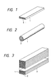
- a structure of the obtained wire test piece is illustrated schematically in FIG. 1.
- the oxide superconductor core 2 has a tape shape structure cladded with a silver sheath 1 containing dispersed zirconium oxide therein.
- a critical temperature Tc and a critical current density Jc of the test piece obtained by repeating the above pressing and calcining four times were determined by a resistivity measurement using a standard four probe method at 77 K under no outer magnetic field, and it was revealed that Tc and Jc were 115 K and 30000 A/cm 2 , respectively.
- a composition of the superconductor forming the core of the wire test piece prepared by the same method as described above was analyzed by an ICP method, and it was revealed that chemical composition of the test piece was Tl 1.68 Ba 1.58 Sr 0.41 Ca 1.98 Cu 3.0 O ⁇ .
- a raw material powder of the wire prepared by the same method as that of the embodiment 1 was made into a wire using a silver pipe, 4.5 mm inner diameter and 6.0 mm outer diameter, including dispersed magnesium oxides particles having a crystal grain size of about 110 nm (1100 ⁇ ) by the same method as the embodiment 1. That is, after the above raw material powder is filled in the silver pipe, an open end of the pipe is closed, and the pipe is drawn to a wire by a drawing bench with a drafting ratio of about 20 %. The worked pipe is annealed in air at 350-400 °C after each drawing operation of two or three times drawings, and finally a wire of 0.7 mm in diameter is obtained.
- a test piece 4 cm long is cut out from the obtained wire, and is fabricated to a flatten shape by being pressed with a pressing machine of 19.6 MPa (20 t/cm 2 ).
- the flatten test piece is calcined in a crucible with a lid in air at 830 °C for 20 hours.
- the obtained test piece is pressed again with the pressing machine of 19.6 MPa (20 t/cm 2 ), and calcined again in a crucible with a lid in air at 830 °C for 20 hours.
- a critical temperature Tc and a critical current density Jc of the test piece obtained by repeating the above pressing and calcining four times were determined by a resistivity measurement using standard four probe method at 77 K under no outer magnetic field, and it was revealed that Tc and Jc were 113 K and 24000 A/cm 2 , respectively.
- a composition of the superconductor forming the core of the wire test piece prepared by the same method as described above was analyzed by an ICP method, and it was revealed that chemical composition of the test piece was Tl 1.71 Ba 1.62 Sr 0.38 Ca 1.96 Cu 3.0 O ⁇ .
- Necessary amounts of composing oxides such as SrO, CaO, and CuO for obtaining a cation ratio of Bi 2 Sr 2 Ca 1 Cu 2 O 8- ⁇ are mixed and pulverized by a crusher for 30 minutes.
- the obtained mixed powder is calcined in an aluminum oxides crucible in air at 800 °C for 20 hours.
- the obtained powder was analyzed by an X-ray diffraction analysis, and it was revealed that a main component of the powder was Bi 2 Sr 2 Ca 1 Cu 2 O 8- ⁇ .
- the powder included a material containing Sr-Ca-Cu-O of which crystal structure was unable to be determined, Bi 2 Sr 2 Cu 1 O ⁇ and others.
- the above calcined material was pulverized by a crusher for about 30 minutes so that its average diameter became a several micrometers, and obtained powder was used as the raw material for a superconducting wire.
- the above raw material powder of the superconducting wire is filled in a pipe, 4.5 mm inner diameter and 6.0 mm outer diameter, one end of which is closed, made from silver wherein 15 % by weight aluminum oxides having a diameter of 260 nm (2600 ⁇ ) is dispersed by a mechanical alloying method.
- a pipe 4.5 mm inner diameter and 6.0 mm outer diameter, one end of which is closed, made from silver wherein 15 % by weight aluminum oxides having a diameter of 260 nm (2600 ⁇ ) is dispersed by a mechanical alloying method.
- an open end is closed, and the pipe is drawn to a wire by a drawing bench with a drafting ratio of about 20 %.
- the worked pipe is annealed in air at 350-400 °C after each drawing operation of two or three times drawings, and finally a wire of 0.7 mm in diameter is obtained.
- a test piece 4 cm long is cut out from the obtained wire, and is put into an aluminum oxides crucible.
- the oxide superconductor Bi 2 Sr 2 Ca 1 Cu 2 O 8- ⁇ 2 forms a core, and wire having a circular cross sectional structure is formed with a cladding made of a silver sheath 1 containing dispersed aluminum oxides therein.
- a critical temperature Tc and a critical current at 4.2 K of the obtained test piece were determined by a resistivity measurement using standard four probe method. It was revealed that Tc and the critical current were 84 K and 115 A, respectively.
- a composition of the superconductor forming the core of the wire test piece prepared by the same method as described above was analyzed by an ICP method, and it was revealed that chemical composition of the test piece was Bi 1.98 Sr 2.01 Ca 0.98 Cu 2 O 8- ⁇ .
- a raw material prepared by an oxalate coprecipitation method so as to be Ba 1.6 Sr 0.4 Ca 2.0 Cu 3.0 O ⁇ in a cation ratio is previously calcined in air at 650 °C for 15 hours, and subsequently the raw material is pulverized by a crusher for 30 minutes. At this time, a necessary amount of thallium oxide for making the cation ratio of the raw material to be Tl 2.0 Ba 1.6 Sr 0.4 Ca 2.0 Cu 3.0 O ⁇ is previously added to the raw material. Powder of the raw material obtained as described above is calcined in an aluminum oxides crucible with a lid in air at 750 °C for 15 hours.
- Main component of the obtained powder was revealed as Tl 2 Ba 2 Ca 1 Cu 2 O 8- ⁇ by powder X-ray diffraction analysis.
- the powder included a material containing Sr-Ca-Cu-O of which crystal structure was unable to be determined, CaO, SrO and others.
- the above calcined material was again pulverized by a crusher for about 30 minutes so that its average diameter became a several micrometers, and obtained powder was used as the raw material for a superconducting wire.
- the above raw material powder of the superconducting wire is filled in a pipe, 6.0 mm inner diameter and 8.0 mm outer diameter, one end of which is closed, made from silver wherein 20 % by weight zirconium oxide having a diameter of 380 nm (3800 ⁇ ) is dispersed by a mechanical alloying method.
- a pipe 6.0 mm inner diameter and 8.0 mm outer diameter, one end of which is closed, made from silver wherein 20 % by weight zirconium oxide having a diameter of 380 nm (3800 ⁇ ) is dispersed by a mechanical alloying method.
- an open end is closed, and the pipe is drawn to a wire by a drawing bench with a drafting ratio of about 20 %.
- the worked pipe is annealed in air at 350-400 °C after each drawing operation of two or three times drawings, and finally a wire of 1.2 mm in diameter is obtained.
- the obtained wire is further manufactured to a tape shape of about 0.7 mm thick and about 6 mm wide by a rolling mill having rollers of 100 mm in diameter, and 20 test pieces of 110 mm long are cut out from the tape shaped wire.
- Each of the 20 test pieces is pressed by a pressing machine of 19.6 MPa (20 t/cm 2 ) to form a flatten shape of about 0.25 mm thick.
- the obtained 20 flatten shape test pieces are stacked and press-welded with a pressure of about 1.96 MPa (2 t/cm 2 ) to form a rectangular cross section.
- the obtained conductor having a rectangular cross section of about 9 mm wide and about 4.7 mm thick is annealed in air at 830 °C for 30 hours.
- the obtained conductor is pressed again with a pressure of about 1.96 MPa (2 t/cm 2 ), and annealed in pure oxygen at 830 °C for 30 hours.
- a cross sectional structure of the obtained conductor is illustrated schematically in FIG. 3.
- the conductor is composed with 20 elementary wires 3 in each of which the oxide superconductor Tl 2.0 Ba 1.6 Sr 0.4 Ca 2.0 Cu 3.0 O ⁇ 2 is used as a core which is coated with a silver sheath 1 containing dispersed zirconium oxide therein.
- Current leads made of copper mesh are respectively connected to each of both ends of the obtained conductor, and voltage terminals made of silver wire were attached at middle portion of the conductor with intervals of respective 30 mm.
- the obtained conductor was fixed to a holder made of fiber reinforced plastic and installed in a cryostat, and a critical current was measured with cooled with liquid nitrogen. The critical current was 630 A.
- Necessary amounts of composing oxides such as SrO, CaO, and CuO for obtaining a cation ratio of Bi 2 Sr 2 Ca 2 Cu 3 O 10- ⁇ are mixed and pulverized by a crusher for 30 minutes.
- the obtained mixed powder is calcined in an aluminum oxides crucible in air at 790 °C for 20 hours.
- the obtained powder was analyzed by an X-ray diffraction analysis, and it was revealed that a main component of the powder was Bi 2 Sr 2 Ca 1 Cu 2 O 8- ⁇ . According to an observation by a scanning electron microscope and an energy dispersive X-ray analysis, the powder included a material containing Sr-Ca-Cu-O of which crystal structure was unable to be determined, SrO and others.
- the above calcined material was pulverized by a crusher for about 30 minutes so that its average diameter became a several micrometers, and obtained powder was used as the raw material for superconducting wire.
- the above raw material powder of the superconducting wire is filled in a pipe, 4.5 mm inner diameter and 6.0 mm outer diameter, one end of which is closed, made from silver wherein 35 % by weight zirconium oxides having a diameter of 260 nm(2600 ⁇ ) is dispersed by a mechanical alloying method. After the filling, an open end is closed, and the pipe is drawn to a wire by a drawing bench with a drafting ratio of about 20 %.
- the worked pipe is annealed in air at 350-400 °C after each drawing operation of two or three times drawings, and finally a wire of 1.2 mm in diameter is obtained.
- the obtained wire is further manufactured to a tape shape of about 0.7 mm thick and about 6 mm wide by a rolling mill having a roll of 100 mm in diameter, and 20 test pieces of 110 mm long are cut out from the tape shaped wire.
- Each of the 20 test pieces is pressed by a pressing machine of 19.6 MPa (20 t/cm 2 ) to form a flatten shape of about 0.25 mm thick.
- the obtained 20 flatten shape test pieces are stacked and press-welded with a pressure of about 1.96 MPa (2 t/cm 2 ) to form a rectangular cross section.
- the obtained conductor having a rectangular cross section of about 9.1 mm wide and about 4.5 mm thick is annealed in air at 800 °C for 15 hours.
- the obtained conductor is pressed again with a pressure of about 1.96 MPa (2 t/cm 2 ), and annealed in air at 830 °C for 40 hours.
- the obtained conductor is pressed again with a pressure of about 1.96 MPa (2 t/cm 2 ), and annealed in air at 845 °C for 40 hours.
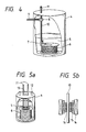
- the conductor obtained in the embodiment 4 was connected to a superconducting coil 6 of 1 T using a NbTi superconducting wire shown in FIG. 4 in a cryostat 4 at a portion for connecting outer power source as for an oxide superconducting current lead 10 via a lead connecting terminal 7.
- the connecting portion of the oxide current lead and the coil is immersed in liquid helium 5, upper portion of the lead is connected with copper lead 11 at a thermal anchor 8 having an inlet for liquid nitrogen 9, and the connecting portion of the oxide current lead 10 and the copper lead 11 is cooled by liquid nitrogen.
- the copper current lead portion has a structure which is cooled by helium gas generated in the cryostat and exhausted outside through a helium gas guide pipe.
- Penetrating heat calibrated to that of 200 A current flows which is estimated from a generated amount of helium gas at power off was about 0.4 W/kA, and penetrating heat at actually 200 A current flows was as small as about 0.55 W/kA. It could be explained that because the oxide superconducting current lead in the cryostat operated in a superconducting condition, and resistance heat generation hardly occurred.
- FIG. 5a illustrates an embodiment of multistructural type super strong magnetic field magnet.
- a superconducting coil 6 is installed in a cryostat 4 cooled with liquid helium 5, and a test port 13 is provided inside of an inner coil 16.
- a coolant inlet 12 is provided at upper portion of the cryostat, and coolant is supplied through the inlet.
- the superconducting coil is excited by being supplied with power from outside through a current lead 11.
- FIG 5b is a schematic illustration indicating a composition of a coil using an oxide superconducting wire relating to the present invention.
- the superconducting coil is composed with three layers, that is, an outer layer coil 14 is a coil using NbTi alloy type superconductor, a middle layer coil is a coil 15 using (Nb/Ti) 3 Sn compound type superconductor, and an inner layer coil is a coil using a circular cross sectional superconductor prepared by the same method as that of the embodiment 3 having Bi 2 Sr 2 Ca 1 Cu 2 O 8- ⁇ superconductor as a core and a silver sheath containing dispersed aluminum oxides therein as a coating.
- a critical current density of the Bi 2 Sr 2 Ca 1 Cu 2 O 8- ⁇ superconductor at a liquid helium temperature in a magnetic field exceeding 18 T is larger than that of conventional NbTi alloy type superconductor and (Nb/Ti) 3 Sn compound type superconductor, and accordingly a larger magnetic field than magnetic fields generated by the above other superconductors can be generated.
- a conductor having preferable mechanical strength, and preferably controlled electric conductivity and thermal conductivity to arbitrary ranges corresponding to its use object can be composed.
- an advantage in improving mechanical strength of the conductors is remarkable, and chemically stable materials can be obtained in accordance with the present invention.
Landscapes
- Chemical & Material Sciences (AREA)
- Engineering & Computer Science (AREA)
- Ceramic Engineering (AREA)
- Superconductors And Manufacturing Methods Therefor (AREA)
- Inorganic Compounds Of Heavy Metals (AREA)
- Physical Vapour Deposition (AREA)
- Containers, Films, And Cooling For Superconductive Devices (AREA)
Claims (13)
- Fil supraconducteur en oxyde, comprenantune âme conductrice (2) en oxyde supraconducteur, etune gaine métallique (1) en métal conducteur, dans laquelle des oxydes métalliques non-supraconducteurs sont dispersés, formée sur le pourtour de ladite âme conductrice (2).caractérisé en ce que
lesdits oxydes métalliques non-supraconducteurs comprennent au moins un oxyde choisi dans un groupe d'oxydes d'aluminium, d'oxydes de zirconium, d'oxydes de magnésium, d'oxydes d'yttrium, d'oxydes de titane et d'oxydes complexes desdits oxydes, et en ce que la résistance à la traction du fil supraconducteur en oxyde est au moins de 98,1 N/mm2 (10 kgf/mm2). - Fil supraconducteur en oxyde selon la revendication 1, dans lequel
lesdits oxydes métalliques non-supraconducteurs ont respectivement un point de fusion supérieur au point de fusion de la gaine métallique (1). - Fil supraconducteur en oxyde selon la revendication 1, dans lequel
lesdits oxydes métalliques non-supraconducteurs sont chimiquement inactifs avec l'oxyde supraconducteur constituant l'âme conductrice (2). - Fil supraconducteur en oxyde selon la revendication 1, dans lequel
les particules desdits oxydes métalliques non-supraconducteurs mesurent au maximum 1000 nm. - Fil supraconducteur en oxyde selon la revendication 1, dans lequel ladite gaine métallique (1) est en argent ou en alliage d'argent.
- Fil supraconducteur en oxyde selon la revendication 5, dans lequel lesdites particules dispersées d'oxydes métalliques ou d'oxydes complexes mesurent en moyenne au maximum 1000 nm.
- Fil supraconducteur en oxyde selon la revendication 1, comprenant une pluralité de fils élémentaires ayant une âme conductrice (2) en oxyde supraconducteur, chaque fil élémentaire ayant une gaine métallique (1) en argent ou en alliage d'argent formée sur le pourtour de ladite âme conductrice (2), et
ladite gaine métallique (1) selon la revendication 1 est formée sur le pourtour de ladite pluralité de fils élémentaires. - Bobine supraconductrice, comprenantune âme conductrice (2) en oxyde supraconducteur, etun fil supraconducteur ayant une gaine (1) selon les revendications 1 et 5 formée sur le pourtour de ladite âme conductrice (2), etune canette pour enrouler ledit fil supraconducteur.
- Bobine supraconductrice composite, comprenantune pluralité de bobines-blocs (14, 15, 16) réalisées séparément sous une forme cylindrique coaxiale, dans lequelau moins une (16) desdites bobines est une âme conductrice en oxyde supraconducteur, et le pourtour de ladite âme conductrice est revêtu d'une gaine (1) selon les revendications 1 et 5.
- Bobine supraconductrice composite selon la revendication 9,dans lequel le pourtour de ladite âme conductrice est revêtu d'une gaine composite constituée d'au moins deux types de matières de gainage, etau moins une desdites matières de gainage est celle revendiquée dans les revendications 1 et 5.
- Bobine supraconductrice composite selon la revendication 10, dans laquelle
les bobines-blocs (14, 15) autres que la bobine conductrice (16) sont en matière supraconductrice du groupe des métaux ou du groupe des composés intermétalliques. - Dispositif supraconducteur, comprenantune bobine supraconductrice (6) en oxyde supraconducteur,un cryostat (4) pour refroidir ladite bobine supraconductrice (6),un conducteur (10) de courant pour fournir de l'extérieur de l'électricité à ladite bobine supraconductrice (6), etune ancre thermique (8) pour maintenir une partie spécifiée dudit conducteur (10) de courant à une température spécifiée,caractériséen ce qu'il comporte une âme conductrice (2) composée dudit oxyde supraconducteur au niveau d'une partie située plus bas que ladite partie spécifiée dudit conducteur (10) de courant maintenu à ladite température spécifiée dans ledit cryostat (4), etun conducteur constitué par une gaine en matière composite (1)selon les revendications 1 et 5.
- Système de stockage d'énergie, comprenantun dispositif de stockage d'énergie comprenant une bobine supraconductrice, etun dispositif d'entrée/sortie d'énergie pour fournir/extraire une énergie électrique audit/dudit dispositif de stockage d'énergie,caractérisé parla formation d'une âme conductrice (2) avec un supraconducteur ayant une température critique supérieure à la température critique d'un supraconducteur utilisé dans ledit système, la formation d'un conducteur composite avec une matière de gainage en argent ou en alliages d'argent sous le pourtour de ladite âme conductrice, etla liaison électrique de ladite âme conductrice (2) avec ledit conducteur composite par un câble à l'aide d'un fil supraconducteur composé de ladite matière de gainage (1) selon les revendications 1 et 5.
Applications Claiming Priority (2)
| Application Number | Priority Date | Filing Date | Title |
|---|---|---|---|
| JP114366/93 | 1993-05-17 | ||
| JP5114366A JPH06325630A (ja) | 1993-05-17 | 1993-05-17 | 酸化物超電導線材及び超電導装置 |
Publications (2)
| Publication Number | Publication Date |
|---|---|
| EP0627773A1 EP0627773A1 (fr) | 1994-12-07 |
| EP0627773B1 true EP0627773B1 (fr) | 1997-03-12 |
Family
ID=14635921
Family Applications (1)
| Application Number | Title | Priority Date | Filing Date |
|---|---|---|---|
| EP94107489A Revoked EP0627773B1 (fr) | 1993-05-17 | 1994-05-13 | Fil supraconducteur d'oxyde et appareil supraconducteur utilisant ce fil |
Country Status (4)
| Country | Link |
|---|---|
| US (1) | US5625332A (fr) |
| EP (1) | EP0627773B1 (fr) |
| JP (1) | JPH06325630A (fr) |
| DE (1) | DE69401992T2 (fr) |
Families Citing this family (30)
| Publication number | Priority date | Publication date | Assignee | Title |
|---|---|---|---|---|
| EP0740314A1 (fr) * | 1995-04-27 | 1996-10-30 | Hitachi, Ltd. | Système magnétique supraconducteur |
| IT1276679B1 (it) * | 1995-06-08 | 1997-11-03 | Pirelli Cavi S P A Ora Pirelli | Procedimento per la produzione di un nastro superconduttore multifilamentare ed elemento conduttore elettrico comprendente |
| JP3386942B2 (ja) * | 1995-10-30 | 2003-03-17 | 株式会社日立製作所 | 酸化物超電導コイル及びその製造方法 |
| JPH1041125A (ja) * | 1996-05-13 | 1998-02-13 | Sumitomo Electric Ind Ltd | 超電導コイル |
| US6397454B1 (en) | 1996-09-26 | 2002-06-04 | American Superconductor Corp. | Decoupling of superconducting elements in high temperature superconducting composites |
| US6305070B1 (en) | 1996-10-15 | 2001-10-23 | American Superconductor Corporation | Performance of oxide dispersion strengthened superconductor composites |
| US5880068A (en) * | 1996-10-18 | 1999-03-09 | American Superconductor, Inc. | High-temperature superconductor lead |
| WO1999007003A1 (fr) * | 1997-08-01 | 1999-02-11 | Eurus Technologies, Inc. | Supraconducteur a haute temperature et procede de fabrication et d'utilisation de celui-ci |
| KR100498972B1 (ko) | 1997-08-05 | 2005-07-01 | 피렐리 카비 에 시스테미 소시에떼 퍼 아찌오니 | 고온 초전도 케이블과 그의 제조 방법 |
| US6762673B1 (en) | 1998-02-10 | 2004-07-13 | American Superconductor Corp. | Current limiting composite material |
| US6188921B1 (en) | 1998-02-10 | 2001-02-13 | American Superconductor Corporation | Superconducting composite with high sheath resistivity |
| GB9805646D0 (en) * | 1998-03-18 | 1998-05-13 | Bicc Plc | Superconducting tapes |
| JP2000277322A (ja) * | 1999-03-26 | 2000-10-06 | Toshiba Corp | 高温超電導コイル、これを用いた高温超電導マグネットおよび高温超電導マグネットシステム |
| JP3489525B2 (ja) * | 2000-02-22 | 2004-01-19 | 住友電気工業株式会社 | 超電導線材およびその製造方法 |
| US7275301B2 (en) * | 2001-01-30 | 2007-10-02 | Shahin Pourrahimi | Method for reinforcing superconducting coils with high-strength materials |
| JP2002270422A (ja) * | 2001-03-08 | 2002-09-20 | Toshiba Corp | 超電導装置および超電導装置の冷却システム |
| DE10201322B4 (de) * | 2002-01-15 | 2004-05-06 | Siemens Ag | Schalteinrichtung der Supraleitungstechnik |
| FR2874451B1 (fr) * | 2004-08-17 | 2006-10-20 | Nexans Sa | Conducteur composite a brins multifilamentaires supraconducteurs |
| JP4774494B2 (ja) * | 2005-01-14 | 2011-09-14 | 成卓 岩熊 | 超電導コイル |
| GB2444090A (en) * | 2006-11-24 | 2008-05-28 | David Peter Lee | Elecrical conductor |
| US7572980B2 (en) * | 2007-01-26 | 2009-08-11 | Ford Global Technologies, Llc | Copper conductor with anodized aluminum dielectric layer |
| JP4790661B2 (ja) * | 2007-05-11 | 2011-10-12 | 公益財団法人鉄道総合技術研究所 | 磁気浮上式鉄道車両用超電導磁石 |
| US7935885B2 (en) * | 2008-07-11 | 2011-05-03 | Ford Global Technologies, Llc | Insulated assembly of insulated electric conductors |
| US9035448B2 (en) * | 2012-06-29 | 2015-05-19 | Materion Corporation | Semiconductor packages having metal composite base plates |
| JP5998110B2 (ja) * | 2013-08-02 | 2016-09-28 | Ckd株式会社 | 電磁コイル、電磁コイルの製造方法、及び電磁アクチュエータ |
| JP6360288B2 (ja) | 2013-09-04 | 2018-07-18 | Ckd株式会社 | 電磁コイルの冷却構造、及び電磁アクチュエータ |
| US9852831B2 (en) * | 2013-11-15 | 2017-12-26 | Hitachi, Ltd. | Superconducting magnet |
| JP6352791B2 (ja) | 2014-12-11 | 2018-07-04 | Ckd株式会社 | コイル用シート、コイル、及びコイルの製造方法 |
| JP6247629B2 (ja) | 2014-12-11 | 2017-12-13 | Ckd株式会社 | コイル用シートの製造方法、及びコイルの製造方法 |
| JP7582616B2 (ja) * | 2021-03-23 | 2024-11-13 | 東芝エネルギーシステムズ株式会社 | 超電導コイル装置、超電導加速器および粒子線治療装置 |
Family Cites Families (5)
| Publication number | Priority date | Publication date | Assignee | Title |
|---|---|---|---|---|
| DE3885961D1 (de) * | 1987-07-24 | 1994-01-13 | Asea Brown Boveri | Verfahren zur Herstellung eines ummantelten Drahtes aus einem keramischen Hochtemperatur-Supraleiter. |
| DE3731266A1 (de) * | 1987-09-17 | 1989-04-06 | Kernforschungsz Karlsruhe | Huellmaterial fuer supraleitende draehte |
| EP0358779B1 (fr) * | 1988-02-26 | 1993-04-14 | Mitsubishi Materials Corporation | Fil supraconducteur de grande resistance et cable presentant une densite elevee de courant, et procede de production |
| JPH03166348A (ja) * | 1989-07-22 | 1991-07-18 | Keiichiro Yoshida | 酸化物超電導粉末用銀シース及び製造法並びに酸化物超電導材 |
| US5384307A (en) * | 1991-11-04 | 1995-01-24 | General Electric Company | Oxide superconductor tape having silver alloy sheath with increased hardness |
-
1993
- 1993-05-17 JP JP5114366A patent/JPH06325630A/ja active Pending
-
1994
- 1994-05-10 US US08/240,314 patent/US5625332A/en not_active Expired - Fee Related
- 1994-05-13 EP EP94107489A patent/EP0627773B1/fr not_active Revoked
- 1994-05-13 DE DE69401992T patent/DE69401992T2/de not_active Revoked
Also Published As
| Publication number | Publication date |
|---|---|
| EP0627773A1 (fr) | 1994-12-07 |
| DE69401992T2 (de) | 1997-06-26 |
| JPH06325630A (ja) | 1994-11-25 |
| DE69401992D1 (de) | 1997-04-17 |
| US5625332A (en) | 1997-04-29 |
Similar Documents
| Publication | Publication Date | Title |
|---|---|---|
| US5625332A (en) | Oxide superconducting wire and superconducting apparatus thereof | |
| AU603942B2 (en) | Devices and systems based on novel superconducting material | |
| US5104849A (en) | Oxide superconductor and method of manufacturing the same | |
| US7018954B2 (en) | Processing of magnesium-boride superconductors | |
| US6591120B1 (en) | Rotationally symmetric oxide superconducting wire and solenoid coil or magnetic field generator incorporating the same | |
| US6194985B1 (en) | Oxide-superconducting coil and a method for manufacturing the same | |
| US5296456A (en) | Ceramic superconductor wire and method of manufacturing the same | |
| EP0472333B1 (fr) | Eléments supraconducteurs allongés comprenant des supraconducteurs à oxyde et bobines supraconductrices | |
| US20030032560A1 (en) | Superconducting article having low AC loss | |
| US20050163644A1 (en) | Processing of magnesium-boride superconductor wires | |
| US20050174202A1 (en) | Superconducting wire material and method for preparation thereof, and superconducting magnet using the same | |
| EP1429399A2 (fr) | Fil supraconducteur et procédé de sa fabrication | |
| Tsapleva et al. | The materials science of modern technical superconducting materials | |
| CA2178565C (fr) | Methode de fabrication de rubans supraconducteurs a filaments multiples et element electriquement conducteur comportant ce type de ruban | |
| Jabur | B2223 High Temperature Superconductor wires in silver sheath, Filament diameter effect on critical temperature and current density | |
| JP2003331660A (ja) | 金属シース超伝導体線材及び超電導コイル並びにその製造方法 | |
| EP0310033A3 (fr) | Fil supraconducteur et procédé pour sa fabrication | |
| EP0409150B1 (fr) | Fil supraconducteur | |
| EP0644601A2 (fr) | Supraconducteur d'oxyde et procédé de sa fabrication | |
| JPH1092630A (ja) | 酸化物超電導コイル | |
| JPH0917249A (ja) | 酸化物超電導線材及びその製造方法 | |
| JP3758455B2 (ja) | 酸化物超電導線材の製造方法 | |
| EP0698930A1 (fr) | Supraconducteur d'oxyde et procédé de fabrication | |
| Jabur et al. | B2212 High Temperature Superconductor Wires in Silver Sheath | |
| JPH11329118A (ja) | 酸化物超電導複合材およびその製造方法 |
Legal Events
| Date | Code | Title | Description |
|---|---|---|---|
| PUAI | Public reference made under article 153(3) epc to a published international application that has entered the european phase |
Free format text: ORIGINAL CODE: 0009012 |
|
| 17P | Request for examination filed |
Effective date: 19940928 |
|
| AK | Designated contracting states |
Kind code of ref document: A1 Designated state(s): DE FR GB |
|
| 17Q | First examination report despatched |
Effective date: 19951121 |
|
| GRAG | Despatch of communication of intention to grant |
Free format text: ORIGINAL CODE: EPIDOS AGRA |
|
| GRAH | Despatch of communication of intention to grant a patent |
Free format text: ORIGINAL CODE: EPIDOS IGRA |
|
| GRAH | Despatch of communication of intention to grant a patent |
Free format text: ORIGINAL CODE: EPIDOS IGRA |
|
| GRAA | (expected) grant |
Free format text: ORIGINAL CODE: 0009210 |
|
| AK | Designated contracting states |
Kind code of ref document: B1 Designated state(s): DE FR GB |
|
| REF | Corresponds to: |
Ref document number: 69401992 Country of ref document: DE Date of ref document: 19970417 |
|
| ET | Fr: translation filed | ||
| PLBI | Opposition filed |
Free format text: ORIGINAL CODE: 0009260 |
|
| PLBF | Reply of patent proprietor to notice(s) of opposition |
Free format text: ORIGINAL CODE: EPIDOS OBSO |
|
| 26 | Opposition filed |
Opponent name: SIEMENS AG Effective date: 19971209 |
|
| PLBF | Reply of patent proprietor to notice(s) of opposition |
Free format text: ORIGINAL CODE: EPIDOS OBSO |
|
| PLBF | Reply of patent proprietor to notice(s) of opposition |
Free format text: ORIGINAL CODE: EPIDOS OBSO |
|
| PGFP | Annual fee paid to national office [announced via postgrant information from national office to epo] |
Ref country code: GB Payment date: 20000502 Year of fee payment: 7 |
|
| PGFP | Annual fee paid to national office [announced via postgrant information from national office to epo] |
Ref country code: DE Payment date: 20000630 Year of fee payment: 7 |
|
| RDAH | Patent revoked |
Free format text: ORIGINAL CODE: EPIDOS REVO |
|
| RDAG | Patent revoked |
Free format text: ORIGINAL CODE: 0009271 |
|
| STAA | Information on the status of an ep patent application or granted ep patent |
Free format text: STATUS: PATENT REVOKED |
|
| 27W | Patent revoked |
Effective date: 20000118 |
|
| GBPR | Gb: patent revoked under art. 102 of the ep convention designating the uk as contracting state |
Free format text: 20000118 |
|
| PGFP | Annual fee paid to national office [announced via postgrant information from national office to epo] |
Ref country code: FR Payment date: 20010502 Year of fee payment: 8 |