EP0627870A2 - Méthode pour l'excitation/régulation d'au moins deux convertisseurs à circuits oscillants parallèles - Google Patents
Méthode pour l'excitation/régulation d'au moins deux convertisseurs à circuits oscillants parallèles Download PDFInfo
- Publication number
- EP0627870A2 EP0627870A2 EP94108055A EP94108055A EP0627870A2 EP 0627870 A2 EP0627870 A2 EP 0627870A2 EP 94108055 A EP94108055 A EP 94108055A EP 94108055 A EP94108055 A EP 94108055A EP 0627870 A2 EP0627870 A2 EP 0627870A2
- Authority
- EP
- European Patent Office
- Prior art keywords
- resonant circuit
- parallel resonant
- direct current
- changed
- source
- Prior art date
- Legal status (The legal status is an assumption and is not a legal conclusion. Google has not performed a legal analysis and makes no representation as to the accuracy of the status listed.)
- Granted
Links
Images



Classifications
-
- H—ELECTRICITY
- H02—GENERATION; CONVERSION OR DISTRIBUTION OF ELECTRIC POWER
- H02M—APPARATUS FOR CONVERSION BETWEEN AC AND AC, BETWEEN AC AND DC, OR BETWEEN DC AND DC, AND FOR USE WITH MAINS OR SIMILAR POWER SUPPLY SYSTEMS; CONVERSION OF DC OR AC INPUT POWER INTO SURGE OUTPUT POWER; CONTROL OR REGULATION THEREOF
- H02M7/00—Conversion of AC power input into DC power output; Conversion of DC power input into AC power output
- H02M7/42—Conversion of DC power input into AC power output without possibility of reversal
- H02M7/44—Conversion of DC power input into AC power output without possibility of reversal by static converters
- H02M7/48—Conversion of DC power input into AC power output without possibility of reversal by static converters using discharge tubes with control electrode or semiconductor devices with control electrode
- H02M7/505—Conversion of DC power input into AC power output without possibility of reversal by static converters using discharge tubes with control electrode or semiconductor devices with control electrode using devices of a thyratron or thyristor type requiring extinguishing means
- H02M7/515—Conversion of DC power input into AC power output without possibility of reversal by static converters using discharge tubes with control electrode or semiconductor devices with control electrode using devices of a thyratron or thyristor type requiring extinguishing means using semiconductor devices only
- H02M7/523—Conversion of DC power input into AC power output without possibility of reversal by static converters using discharge tubes with control electrode or semiconductor devices with control electrode using devices of a thyratron or thyristor type requiring extinguishing means using semiconductor devices only with LC-resonance circuit in the main circuit
- H02M7/5233—Conversion of DC power input into AC power output without possibility of reversal by static converters using discharge tubes with control electrode or semiconductor devices with control electrode using devices of a thyratron or thyristor type requiring extinguishing means using semiconductor devices only with LC-resonance circuit in the main circuit the commutation elements being in a push-pull arrangement
- H02M7/5236—Conversion of DC power input into AC power output without possibility of reversal by static converters using discharge tubes with control electrode or semiconductor devices with control electrode using devices of a thyratron or thyristor type requiring extinguishing means using semiconductor devices only with LC-resonance circuit in the main circuit the commutation elements being in a push-pull arrangement in a series push-pull arrangement
-
- C—CHEMISTRY; METALLURGY
- C21—METALLURGY OF IRON
- C21C—PROCESSING OF PIG-IRON, e.g. REFINING, MANUFACTURE OF WROUGHT-IRON OR STEEL; TREATMENT IN MOLTEN STATE OF FERROUS ALLOYS
- C21C5/00—Manufacture of carbon-steel, e.g. plain mild steel, medium carbon steel or cast steel or stainless steel
- C21C5/52—Manufacture of steel in electric furnaces
- C21C5/5229—Manufacture of steel in electric furnaces in a direct current [DC] electric arc furnace
-
- H—ELECTRICITY
- H02—GENERATION; CONVERSION OR DISTRIBUTION OF ELECTRIC POWER
- H02M—APPARATUS FOR CONVERSION BETWEEN AC AND AC, BETWEEN AC AND DC, OR BETWEEN DC AND DC, AND FOR USE WITH MAINS OR SIMILAR POWER SUPPLY SYSTEMS; CONVERSION OF DC OR AC INPUT POWER INTO SURGE OUTPUT POWER; CONTROL OR REGULATION THEREOF
- H02M5/00—Conversion of AC power input into AC power output, e.g. for change of voltage, for change of frequency, for change of number of phases
- H02M5/40—Conversion of AC power input into AC power output, e.g. for change of voltage, for change of frequency, for change of number of phases with intermediate conversion into DC
- H02M5/42—Conversion of AC power input into AC power output, e.g. for change of voltage, for change of frequency, for change of number of phases with intermediate conversion into DC by static converters
- H02M5/44—Conversion of AC power input into AC power output, e.g. for change of voltage, for change of frequency, for change of number of phases with intermediate conversion into DC by static converters using discharge tubes or semiconductor devices to convert the intermediate DC into AC
- H02M5/443—Conversion of AC power input into AC power output, e.g. for change of voltage, for change of frequency, for change of number of phases with intermediate conversion into DC by static converters using discharge tubes or semiconductor devices to convert the intermediate DC into AC using devices of a thyratron or thyristor type requiring extinguishing means
- H02M5/45—Conversion of AC power input into AC power output, e.g. for change of voltage, for change of frequency, for change of number of phases with intermediate conversion into DC by static converters using discharge tubes or semiconductor devices to convert the intermediate DC into AC using devices of a thyratron or thyristor type requiring extinguishing means using semiconductor devices only
- H02M5/4505—Conversion of AC power input into AC power output, e.g. for change of voltage, for change of frequency, for change of number of phases with intermediate conversion into DC by static converters using discharge tubes or semiconductor devices to convert the intermediate DC into AC using devices of a thyratron or thyristor type requiring extinguishing means using semiconductor devices only having a rectifier with controlled elements
-
- H—ELECTRICITY
- H05—ELECTRIC TECHNIQUES NOT OTHERWISE PROVIDED FOR
- H05B—ELECTRIC HEATING; ELECTRIC LIGHT SOURCES NOT OTHERWISE PROVIDED FOR; CIRCUIT ARRANGEMENTS FOR ELECTRIC LIGHT SOURCES, IN GENERAL
- H05B6/00—Heating by electric, magnetic or electromagnetic fields
- H05B6/02—Induction heating
- H05B6/06—Control, e.g. of temperature, of power
- H05B6/067—Control, e.g. of temperature, of power for melting furnaces
-
- Y—GENERAL TAGGING OF NEW TECHNOLOGICAL DEVELOPMENTS; GENERAL TAGGING OF CROSS-SECTIONAL TECHNOLOGIES SPANNING OVER SEVERAL SECTIONS OF THE IPC; TECHNICAL SUBJECTS COVERED BY FORMER USPC CROSS-REFERENCE ART COLLECTIONS [XRACs] AND DIGESTS
- Y02—TECHNOLOGIES OR APPLICATIONS FOR MITIGATION OR ADAPTATION AGAINST CLIMATE CHANGE
- Y02P—CLIMATE CHANGE MITIGATION TECHNOLOGIES IN THE PRODUCTION OR PROCESSING OF GOODS
- Y02P10/00—Technologies related to metal processing
- Y02P10/20—Recycling
-
- Y—GENERAL TAGGING OF NEW TECHNOLOGICAL DEVELOPMENTS; GENERAL TAGGING OF CROSS-SECTIONAL TECHNOLOGIES SPANNING OVER SEVERAL SECTIONS OF THE IPC; TECHNICAL SUBJECTS COVERED BY FORMER USPC CROSS-REFERENCE ART COLLECTIONS [XRACs] AND DIGESTS
- Y02—TECHNOLOGIES OR APPLICATIONS FOR MITIGATION OR ADAPTATION AGAINST CLIMATE CHANGE
- Y02P—CLIMATE CHANGE MITIGATION TECHNOLOGIES IN THE PRODUCTION OR PROCESSING OF GOODS
- Y02P10/00—Technologies related to metal processing
- Y02P10/25—Process efficiency
Definitions
- the invention relates to a method for controlling at least two parallel resonant circuit inverters according to the preamble of claim 1.
- a parallel resonant circuit converter for inductive heating is known from Siemens magazine 45 (1971), number 9, pages 601 to 606.
- This is an intermediate circuit converter circuit with impressed current in the intermediate circuit.
- the direct current generated by the line-side rectifier from an AC line voltage is converted into a medium-frequency AC current in the load-side inverter.
- the load consists of an inductor, which inductively transfers the active power to the material to be heated (e.g. molten metal). To cover the high reactive power requirement, the inductor is supplemented with the help of one or more compensation capacitors to form a parallel resonant circuit.
- the impressed intermediate circuit current is alternately switched to the load in time with the operating frequency via diagonally opposite valve branches and generates an approximately sinusoidal voltage in it.
- the emerging Operating frequency is directly related to the natural frequency of the load circuit due to the load timing.
- each parallel resonant circuit inverter In the case of a system consisting of several induction furnaces, each with its own parallel resonant circuit inverter, it is common to connect each parallel resonant circuit inverter to its own direct current source, i.e. to connect your own rectifier with a DC link, which is very expensive.
- the invention has for its object to provide a method for controlling / regulating the converter valves of two or more parallel resonant circuit inverters of two or more induction furnaces of the type mentioned initially, which are fed from a common direct current source or a common direct voltage source (with a choke connected in series), which is a stepless Setting the power supplied by the DC power source or the DC voltage source and distribution to the individual induction furnaces allows.
- each of the inverters with a load circuit can be regarded as a resistor behind the intermediate circuit (DC intermediate circuit).
- the value of these resistors is changed by suitable inverter control.
- the advantages achievable with the invention consist in particular in the fact that two or more parallel resonant circuit inverters - each of which is associated with its own induction furnace - from a common direct current source or a common direct voltage source with only one Rectifiers for converting an AC line voltage into a DC voltage.
- the rectifier power currently generated corresponds to the sum of all currently used parallel resonant circuit inverter powers. It is possible, for example, to measure the installed rectifier output based on the installed output of a parallel resonant circuit inverter. This has the advantage of high cost savings compared to conventional technology, in which each parallel resonant circuit inverter requires its own rectifier with the power matched to the parallel resonant circuit inverter.
- the invention it is possible to continuously and independently adjust the parallel resonant circuit inverter powers currently consumed, the sum of all currently required inverter powers of course not being allowed to exceed the installed rectifier power. It is particularly advantageous if the total of the inverter power currently consumed is always 100% of the installed rectifier power during all different operating phases, since the rectifier is then used optimally.
- a very wide power control range (1: 100 and more) is possible with both inverters.
- FIG. 1 shows two parallel resonant circuits, each fed by its own inverter, from two induction furnaces.
- a first inverter 12 consisting of four converter valves A11, A12, B11, B12 can be seen, the anodes of the valves A11 and B11 being located on a smoothing inductor Ld1 at the positive pole 1 and the cathodes of the valves B12 and A12 at the connection point 11 of both inverters .
- the connection point 11 is also a negative pole for the first inverter 12.
- connection point of the cathode of the valve A11 and the anode of the valve B12 forms the first load connection 3 and the connection point of the cathode of the valve B11 and the anode of the valve A12 forms the second load connection 4 of the first inverter 12.
- a parallel resonant circuit 5 is connected between the two load connections 3, 4, a commutation inductance LK1 being arranged between the load connection 3 and the parallel resonant circuit 5.
- the parallel resonant circuit 5 consists of a coil 6 of a first induction furnace and a capacitor C1 connected in parallel (compensation capacitor), wherein the coil 6 has an inductance LO1 and an ohmic resistor RO1.
- a second inverter 13 is arranged between the connection point 11 and the negative pole 2 of a direct current source or direct voltage source. Positive pole 1 and negative pole 2 are preferably fed from a three-phase network via a rectifier.
- the second inverter 13 has four converter valves A21, A22, B21, B22 and two load connections 7, 8 and feeds a second parallel resonant circuit 9 with coil 10 (with inductance LO2 and resistor RO2) and capacitor C2 located between the two load connections 7, 8.
- a commutation inductance LK2 is connected between load terminal 7 and parallel resonant circuit 9.
- the input current of the two inverters 12, 13, i.e. the current which is fed by the direct current source or direct voltage source and flows via the smoothing inductor Ld1 is denoted by Id.
- the current flows via the valves A11, A12, B11, B12 or A21, A22, B21, B22 are IA11, IA12, IB11, IB12 or IA21, IA22, IB21, IB22.
- the output current of the first inverter 12, i.e. the current flow through the commutation inductance LK1 and the parallel resonant circuit 5 is designated IW1.
- the voltage on the first capacitor C1 is UC1.
- the output current of the second inverter 13 is designated IW2 and the voltage on the second capacitor is UC2.
- the natural frequencies of both resonant circuits can be different, i.e. the frequency of the voltage UC2 is independent of the frequency of the voltage UC1.
- the frequencies of the voltages UC1, UC2 depend on the capacitances of the capacitors C1, C2 and on the resistors RO1, RO2 and the inductances LO1, LO2 of the induction furnaces (the furnace filling influences the frequency, among other things).
- the valves of the inverters are controlled taking these frequencies into account, whereby boundary conditions such as sufficiently high voltage at the capacitors of the parallel resonant circuits and valve closing times must be observed.
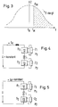
- FIG. 3 shows the relationship between the impedance of an oscillating circuit and the oscillating circuit frequency.
- the resonant circuit frequency is always higher than the resonance frequency.
- the load phase angle ⁇ ⁇ ⁇ M or the corresponding ignition pulses are set in the hatched area of the impedance curve (working area). As can be seen, the frequency f increases as the load phase angle ⁇ increases, while the impedance Z decreases at the same time.
- the operator of the induction furnaces wants to specify a changed power P1 'for the first resonant circuit and P2' for the second resonant circuit, the power sum P1 '+ P2' of course not the maximum power of the DC voltage source may exceed.
- the changed current flow I d 'results according to I. d ' (P1' + P2 ') / U .
- load phase angles ⁇ 1 'and ⁇ 2' to be set correspond to the impedances Z1 'and Z2'.
- the DC voltage source for setting the changed powers P1 ', P2' remains fully modulated as far as possible.
- the voltage U must be reduced by intervening in the control of the DC voltage source (line-side rectifier) in order to reduce the power of the DC voltage source.
- the operator of the induction furnaces wants to specify a changed power P1 'for the first resonant circuit and P2' for the second resonant circuit, the power sum P1 '+ P2' must of course not exceed the maximum power of the direct current source.
- load phase angles ⁇ 1 'and ⁇ 2' to be set correspond to the impedances Z1 'and Z2'.
- the DC power source for setting the changed powers P1 ', P2' remains fully modulated as far as possible.
- the current I d must be reduced by intervening in the control of the direct current source (line-side rectifier) in order to reduce the power of the direct current source .
- the powers supplied to the first or second induction furnace can be set independently of one another and continuously, for example the first induction furnace can be operated with 80% of its nominal output and the second induction furnace with 50% of its nominal output.
- the total power for induction furnaces with the same nominal output is 100% or less in all operating cases, ie the first induction furnace is operated, for example, with 10% of its nominal output and the second induction furnace simultaneously with 90% of its nominal output.
- the direct current source e.g.
- rectifier with a direct current intermediate circuit or the direct voltage source with a series-connected choke only has to be designed for 100% of the power of a parallel resonant circuit inverter, but can alternately feed two induction furnaces with, for example, 90% power, whereby one furnace each, for example in melting operation with 90% output, and the other furnace works simultaneously in heating operation with 10% output. It is of course possible to work both induction furnaces at the same time in keeping warm mode with 10% output each to let, for this purpose the power to be emitted from the direct current source or direct voltage source can be reduced, for example, by correspondingly influencing the valves of the line-side rectifier.
- FIG. 6 shows a system with four parallel resonant circuit inverters fed by a direct current source and a control device for power setting and power distribution.
- Four parallel resonant circuit inverters 12, 13, 14, 15 can be seen, which are on the DC side in series between positive pole 1 and negative pole 2 of the direct current source, a rectifier 22 connected to a three-phase network 23 and the smoothing choke Ld1 serving as a direct current source.
- the coils 6, 10, 20, 21 and the capacitors C1, C2, C3, C4 of the parallel resonant circuits are assigned to induction furnaces 16, 17, 18, 19.
- the DC power source is preferably designed for 200% of this output, it being possible, for example, to optimally operate two induction furnaces with 90% nominal output each (melting operation) and two induction furnaces with 10% nominal output each (holding operation).
- the computing element 24 may limit the power to be set to the maximum value of the direct current source if the sum P1 '+ P2' + P3 '+ P4' should exceed this maximum value.
- a computing element 25 determines the impedance Z 1 'from P 1' and U '.
- a computing element 26 from P2 'and U' determine the impedance Z2 '
- a computing element 27 from P3' and U 'the impedance Z3' and a computing element 28 from P4 'and U' the impedance Z4 ' are examples of the impedance Z4 '.
- the impedances Z1 'to Z4' determined by the arithmetic elements 25 to 28 are supplied to memory elements 29 to 32.
- the impedance curve according to FIG. 3 is stored in these memory elements, so that the load phase angles ⁇ 'to be set can be determined from the impedances Z'.
- memory element 29 determines the load phase angle ⁇ 1 'from impedance Z1'
- memory element 30 determines the load phase angle ⁇ 2 'from impedance Z2'
- memory element 31 determines the load phase angle ⁇ 3 'from impedance Z3'
- memory element 32 determines the load phase angle ⁇ 4 'from impedance Z Imp'.
- Ignition pulse generators 33, 34, 35, 36 generate the ignition pulses corresponding to the determined load phase angles ⁇ 1 ', ⁇ 2', ⁇ 3 ', ⁇ 4' for the valves of the parallel resonant circuit inverters 12, 13, 14, 15th
- the memory element 29 ... 32 concerned sends a corresponding signal to a regulating / control device 37 of the rectifier 22, so that the current I d is reduced, to bring about a reduction in performance.
- the current I d is reduced in such a way that the inverter concerned can be operated with a load phase angle which is slightly above the value ⁇ M.
- FIG. 7 shows a system with a control device as shown in FIG. 6, but in contrast to this in the case of a supply with a DC voltage source with a choke connected in series.
- the (e.g. digital) control device changes as follows: A computing element 38 determines from the changed powers to be set P1 ', P2', P3 ', P4' and the direct voltage U as an auxiliary variable the changed current I d 'necessary for the total power to be set.
- a computing element 39 determines the impedance Z 1 'from P 1' and I d '.
- a computing element 40 from P2 'and I d ' determine the impedance Z2 '
- a regulating / control device 43 of the DC voltage source is only influenced when one of the load phase angles ⁇ 1 '... ⁇ 4' reaches the value ⁇ M in order to reduce the voltage U and thus achieve a reduction in the current I d .
- the current I d is reduced in such a way that the rectifier is controlled back (reduction of its output voltage).
Landscapes
- Engineering & Computer Science (AREA)
- Power Engineering (AREA)
- Chemical & Material Sciences (AREA)
- Physics & Mathematics (AREA)
- Electromagnetism (AREA)
- Manufacturing & Machinery (AREA)
- Materials Engineering (AREA)
- Metallurgy (AREA)
- Organic Chemistry (AREA)
- Inverter Devices (AREA)
Applications Claiming Priority (4)
| Application Number | Priority Date | Filing Date | Title |
|---|---|---|---|
| DE4318081 | 1993-06-01 | ||
| DE4318081 | 1993-06-01 | ||
| DE4403078 | 1994-02-02 | ||
| DE4403078A DE4403078A1 (de) | 1993-06-01 | 1994-02-02 | Verfahren zur Steuerung/Regelung von mindestens zwei Parallelschwingkreiswechselrichtern |
Publications (3)
| Publication Number | Publication Date |
|---|---|
| EP0627870A2 true EP0627870A2 (fr) | 1994-12-07 |
| EP0627870A3 EP0627870A3 (fr) | 1995-04-26 |
| EP0627870B1 EP0627870B1 (fr) | 1999-10-06 |
Family
ID=25926361
Family Applications (1)
| Application Number | Title | Priority Date | Filing Date |
|---|---|---|---|
| EP94108055A Expired - Lifetime EP0627870B1 (fr) | 1993-06-01 | 1994-05-26 | Méthode pour l'excitation/régulation d'au moins deux convertisseurs à circuits oscillants parallèles |
Country Status (2)
| Country | Link |
|---|---|
| EP (1) | EP0627870B1 (fr) |
| DE (2) | DE4403078A1 (fr) |
Cited By (5)
| Publication number | Priority date | Publication date | Assignee | Title |
|---|---|---|---|---|
| GB2300080A (en) * | 1995-04-20 | 1996-10-23 | Abb Patent Gmbh | Method of driving the converter valves of parallel resonant circuit inverters connected in series on the direct-current side |
| WO1997009867A1 (fr) * | 1995-09-08 | 1997-03-13 | Massachusetts Institute Of Technology | Dispositif d'equilibrage de charge d'induction pour le chauffage en parallele de pieces multiples |
| EP0762624A3 (fr) * | 1995-09-05 | 1998-07-08 | Kabushiki Kaisha Toshiba | Système de commande pour un système de conversion de puissance |
| WO2017021373A3 (fr) * | 2015-07-31 | 2017-04-06 | TRUMPF Hüttinger GmbH + Co. KG | Inducteur et dispositif d'induction |
| CN112648693A (zh) * | 2020-12-18 | 2021-04-13 | 青岛海信日立空调系统有限公司 | 一种空调及多通道pfc电路控制方法 |
Families Citing this family (1)
| Publication number | Priority date | Publication date | Assignee | Title |
|---|---|---|---|---|
| DE10325227A1 (de) * | 2003-06-04 | 2005-01-20 | Ald Vacuum Technologies Ag | Heiz- und Schmelzeinrichtung mit mehreren jeweils mindestens eine eigene Arbeitsspule aufweisenden Heizzonen |
Family Cites Families (2)
| Publication number | Priority date | Publication date | Assignee | Title |
|---|---|---|---|---|
| DE3710085C2 (de) * | 1987-03-27 | 1994-07-21 | Asea Brown Boveri | Einrichtung zur induktiven Erwärmung eines Werkstückes mittels mehrerer Induktoren |
| DE4209645A1 (de) * | 1992-03-25 | 1993-09-30 | Abb Patent Gmbh | Verfahren zur Ansteuerung der Stromrichterventile von zwei oder mehr aus einer gemeinsamen Gleichstromquelle gespeisten Parallelschwingkreiswechselrichtern mit jeweils einem Induktionsofen und Anlage zur Durchführung des Verfahrens |
-
1994
- 1994-02-02 DE DE4403078A patent/DE4403078A1/de not_active Withdrawn
- 1994-05-26 EP EP94108055A patent/EP0627870B1/fr not_active Expired - Lifetime
- 1994-05-26 DE DE59408795T patent/DE59408795D1/de not_active Expired - Lifetime
Cited By (9)
| Publication number | Priority date | Publication date | Assignee | Title |
|---|---|---|---|---|
| GB2300080A (en) * | 1995-04-20 | 1996-10-23 | Abb Patent Gmbh | Method of driving the converter valves of parallel resonant circuit inverters connected in series on the direct-current side |
| GB2300080B (en) * | 1995-04-20 | 1999-06-02 | Abb Patent Gmbh | Method of driving the converter valves of parallel resonant circuit inverters connected in series on the direct-current side |
| EP0762624A3 (fr) * | 1995-09-05 | 1998-07-08 | Kabushiki Kaisha Toshiba | Système de commande pour un système de conversion de puissance |
| WO1997009867A1 (fr) * | 1995-09-08 | 1997-03-13 | Massachusetts Institute Of Technology | Dispositif d'equilibrage de charge d'induction pour le chauffage en parallele de pieces multiples |
| US5660754A (en) * | 1995-09-08 | 1997-08-26 | Massachusetts Institute Of Technology | Induction load balancer for parallel heating of multiple parts |
| WO2017021373A3 (fr) * | 2015-07-31 | 2017-04-06 | TRUMPF Hüttinger GmbH + Co. KG | Inducteur et dispositif d'induction |
| CN107852783A (zh) * | 2015-07-31 | 2018-03-27 | 通快许廷格两合公司 | 电感器和电感器装置 |
| CN112648693A (zh) * | 2020-12-18 | 2021-04-13 | 青岛海信日立空调系统有限公司 | 一种空调及多通道pfc电路控制方法 |
| CN112648693B (zh) * | 2020-12-18 | 2023-08-04 | 青岛海信日立空调系统有限公司 | 一种空调及多通道pfc电路控制方法 |
Also Published As
| Publication number | Publication date |
|---|---|
| DE4403078A1 (de) | 1994-12-08 |
| EP0627870A3 (fr) | 1995-04-26 |
| DE59408795D1 (de) | 1999-11-11 |
| EP0627870B1 (fr) | 1999-10-06 |
Similar Documents
| Publication | Publication Date | Title |
|---|---|---|
| DE2653333C2 (de) | Anordnung zur stufenlosen Kompensation von Blindleistung in einem elektrischen Wechselspannungsnetz | |
| DE69313340T2 (de) | Steuereinrichtung für Leistungskonverter und Steuereinrichtung für Fahrzeug mit elektrischem Motor | |
| EP0144556B1 (fr) | Compensateur de puissance réactive pour la compensation d'une composante de courant réactif, dans un réseau à courant alternatif | |
| DE2415398C3 (de) | Schaltungsanordnung mit einer Anzahl von Umrichtern, insbesondere von Direktumrichtern in Sternschaltung | |
| EP0639880B1 (fr) | Méthode de stabilisation d'un réseau vis à vis des oscillations d'énergie réactive et appareil de compensation d'énergie réactive | |
| DE112015002279T5 (de) | Energie-umsetzungsvorrichtung | |
| DE4200329C2 (de) | Regelbare Speisestromquelle | |
| EP0716561B1 (fr) | Appareil à rayons X comportant une unité pour l'alimentation en puissance d'un tube à rayons X | |
| DE2651229A1 (de) | Geregelte hochspannungs-gleichstromversorgung | |
| EP0026374B1 (fr) | Dispositif pour le transfert d'énergie électrique de grande puissance d'un réseau d'alimentation triphasé à fréquence plus élevée à un réseau de charge monophasé à fréquence plus basse | |
| EP0627870A2 (fr) | Méthode pour l'excitation/régulation d'au moins deux convertisseurs à circuits oscillants parallèles | |
| DE4306999A1 (de) | System zum Zuführen von elektrischer Leistung zu einem Induktionsofen | |
| CH679716A5 (fr) | ||
| DE19531210A1 (de) | Steuersystem für einphasigen PWM-Wandler | |
| DE4344709C2 (de) | Verfahren zur Umwandlung von unterschiedlich großen Gleich- oder Wechselspannungen in eine beliebig vorgegebene Spannung | |
| EP0562471B1 (fr) | Procédé pour l'excitation des valves de deux ou plus convertisseurs avec des circuits oscillants parallèles alimentés d'un courant continu d'une source commune chaque convertisseur muni avec un four à induction chaque fois et un arrangement pour l'exécution du procédé | |
| EP0235578B1 (fr) | Dispositif d'alimentation de courant pour une charge composée de plusieurs circuits oscillants en parallèle et montés individuellement en parallèle sur une barre omnibus | |
| DE2641294C2 (de) | Schaltungsanordnung mit einer Anzahl von Umrichtern mit Einphasen-Wechsel-Spannungsausgang | |
| EP0936956B1 (fr) | Procede et dispositif generateurs de courant de soudage pour une machine a souder par resistance | |
| DE2643934C2 (de) | Einrichtung zur Kompensation der Blindleistung eines Verbrauchers, der aus einem mehrphasigen Wechselspannungsnetz gespeist ist, und/oder zum Vermindern der Unsymmetrie in diesem Wechselspannungsnetz | |
| DE3213778C2 (fr) | ||
| EP1745542A2 (fr) | Procede pour commander un convertisseur, notamment pour generer une puissance active destinee au chauffage par induction | |
| WO2004001778A1 (fr) | Circuiterie destinee a la production d'une tension de tube radiogene | |
| DE19514537B4 (de) | Verfahren zur Ansteuerung der Stromrichterventile von gleichstromseitig in Reihe geschalteten Parallelschwingkreiswechselrichtern | |
| DE3130356C2 (de) | Regelanordnung zur gleichmäßigen Lastverteilung von zwei ausgangsseitig parallelgeschalteten Stromversorgungsgeräten |
Legal Events
| Date | Code | Title | Description |
|---|---|---|---|
| PUAI | Public reference made under article 153(3) epc to a published international application that has entered the european phase |
Free format text: ORIGINAL CODE: 0009012 |
|
| AK | Designated contracting states |
Kind code of ref document: A2 Designated state(s): DE FR GB IT |
|
| PUAL | Search report despatched |
Free format text: ORIGINAL CODE: 0009013 |
|
| AK | Designated contracting states |
Kind code of ref document: A3 Designated state(s): DE FR GB IT |
|
| 17P | Request for examination filed |
Effective date: 19950705 |
|
| GRAG | Despatch of communication of intention to grant |
Free format text: ORIGINAL CODE: EPIDOS AGRA |
|
| GRAG | Despatch of communication of intention to grant |
Free format text: ORIGINAL CODE: EPIDOS AGRA |
|
| GRAH | Despatch of communication of intention to grant a patent |
Free format text: ORIGINAL CODE: EPIDOS IGRA |
|
| 17Q | First examination report despatched |
Effective date: 19990305 |
|
| GRAH | Despatch of communication of intention to grant a patent |
Free format text: ORIGINAL CODE: EPIDOS IGRA |
|
| GRAA | (expected) grant |
Free format text: ORIGINAL CODE: 0009210 |
|
| AK | Designated contracting states |
Kind code of ref document: B1 Designated state(s): DE FR GB IT |
|
| REF | Corresponds to: |
Ref document number: 59408795 Country of ref document: DE Date of ref document: 19991111 |
|
| ET | Fr: translation filed | ||
| GBT | Gb: translation of ep patent filed (gb section 77(6)(a)/1977) |
Effective date: 19991108 |
|
| ITF | It: translation for a ep patent filed | ||
| PLBE | No opposition filed within time limit |
Free format text: ORIGINAL CODE: 0009261 |
|
| STAA | Information on the status of an ep patent application or granted ep patent |
Free format text: STATUS: NO OPPOSITION FILED WITHIN TIME LIMIT |
|
| 26N | No opposition filed | ||
| REG | Reference to a national code |
Ref country code: GB Ref legal event code: IF02 |
|
| REG | Reference to a national code |
Ref country code: FR Ref legal event code: TP |
|
| REG | Reference to a national code |
Ref country code: GB Ref legal event code: 732E |
|
| PGFP | Annual fee paid to national office [announced via postgrant information from national office to epo] |
Ref country code: DE Payment date: 20130531 Year of fee payment: 20 Ref country code: GB Payment date: 20130521 Year of fee payment: 20 |
|
| PGFP | Annual fee paid to national office [announced via postgrant information from national office to epo] |
Ref country code: FR Payment date: 20130603 Year of fee payment: 20 Ref country code: IT Payment date: 20130529 Year of fee payment: 20 |
|
| REG | Reference to a national code |
Ref country code: DE Ref legal event code: R071 Ref document number: 59408795 Country of ref document: DE |
|
| REG | Reference to a national code |
Ref country code: GB Ref legal event code: PE20 Expiry date: 20140525 |
|
| PG25 | Lapsed in a contracting state [announced via postgrant information from national office to epo] |
Ref country code: GB Free format text: LAPSE BECAUSE OF EXPIRATION OF PROTECTION Effective date: 20140525 |
|
| PG25 | Lapsed in a contracting state [announced via postgrant information from national office to epo] |
Ref country code: DE Free format text: LAPSE BECAUSE OF EXPIRATION OF PROTECTION Effective date: 20140527 |