EP0628295A1 - Einfüllvorrichtung für Knochenzement - Google Patents
Einfüllvorrichtung für Knochenzement Download PDFInfo
- Publication number
- EP0628295A1 EP0628295A1 EP94250124A EP94250124A EP0628295A1 EP 0628295 A1 EP0628295 A1 EP 0628295A1 EP 94250124 A EP94250124 A EP 94250124A EP 94250124 A EP94250124 A EP 94250124A EP 0628295 A1 EP0628295 A1 EP 0628295A1
- Authority
- EP
- European Patent Office
- Prior art keywords
- filling
- cannula
- bone
- strip elements
- bone cement
- Prior art date
- Legal status (The legal status is an assumption and is not a legal conclusion. Google has not performed a legal analysis and makes no representation as to the accuracy of the status listed.)
- Granted
Links
- 239000002639 bone cement Substances 0.000 title claims abstract description 19
- 210000000988 bone and bone Anatomy 0.000 claims abstract description 30
- 239000000463 material Substances 0.000 claims description 32
- 238000004026 adhesive bonding Methods 0.000 claims description 5
- 239000004033 plastic Substances 0.000 claims description 2
- 239000000945 filler Substances 0.000 claims 5
- 239000010410 layer Substances 0.000 claims 3
- 238000010276 construction Methods 0.000 claims 1
- 230000011218 segmentation Effects 0.000 claims 1
- 239000002356 single layer Substances 0.000 claims 1
- 239000004568 cement Substances 0.000 abstract description 3
- 238000001356 surgical procedure Methods 0.000 abstract 1
- 238000007789 sealing Methods 0.000 description 6
- 238000011161 development Methods 0.000 description 5
- 230000018109 developmental process Effects 0.000 description 5
- 230000009471 action Effects 0.000 description 2
- 230000006835 compression Effects 0.000 description 2
- 238000007906 compression Methods 0.000 description 2
- 230000002349 favourable effect Effects 0.000 description 2
- 238000005429 filling process Methods 0.000 description 2
- 230000009467 reduction Effects 0.000 description 2
- 230000000630 rising effect Effects 0.000 description 2
- 230000015572 biosynthetic process Effects 0.000 description 1
- 230000008859 change Effects 0.000 description 1
- 230000000694 effects Effects 0.000 description 1
- 239000013013 elastic material Substances 0.000 description 1
- 238000002513 implantation Methods 0.000 description 1
- 238000004519 manufacturing process Methods 0.000 description 1
- 238000000034 method Methods 0.000 description 1
- 230000035515 penetration Effects 0.000 description 1
- 230000000717 retained effect Effects 0.000 description 1
- 230000003068 static effect Effects 0.000 description 1
- 230000007704 transition Effects 0.000 description 1
Images


Classifications
-
- A—HUMAN NECESSITIES
- A61—MEDICAL OR VETERINARY SCIENCE; HYGIENE
- A61B—DIAGNOSIS; SURGERY; IDENTIFICATION
- A61B17/00—Surgical instruments, devices or methods
- A61B17/56—Surgical instruments or methods for treatment of bones or joints; Devices specially adapted therefor
- A61B17/58—Surgical instruments or methods for treatment of bones or joints; Devices specially adapted therefor for osteosynthesis, e.g. bone plates, screws or setting implements
- A61B17/88—Osteosynthesis instruments; Methods or means for implanting or extracting internal or external fixation devices
- A61B17/8802—Equipment for handling bone cement or other fluid fillers
- A61B17/8805—Equipment for handling bone cement or other fluid fillers for introducing fluid filler into bone or extracting it
- A61B17/8808—Equipment for handling bone cement or other fluid fillers for introducing fluid filler into bone or extracting it with sealing collar for bone cavity
-
- A—HUMAN NECESSITIES
- A61—MEDICAL OR VETERINARY SCIENCE; HYGIENE
- A61B—DIAGNOSIS; SURGERY; IDENTIFICATION
- A61B17/00—Surgical instruments, devices or methods
- A61B17/56—Surgical instruments or methods for treatment of bones or joints; Devices specially adapted therefor
- A61B17/58—Surgical instruments or methods for treatment of bones or joints; Devices specially adapted therefor for osteosynthesis, e.g. bone plates, screws or setting implements
- A61B17/88—Osteosynthesis instruments; Methods or means for implanting or extracting internal or external fixation devices
- A61B17/8802—Equipment for handling bone cement or other fluid fillers
- A61B17/8805—Equipment for handling bone cement or other fluid fillers for introducing fluid filler into bone or extracting it
- A61B17/8811—Equipment for handling bone cement or other fluid fillers for introducing fluid filler into bone or extracting it characterised by the introducer tip, i.e. the part inserted into or onto the bone
-
- A—HUMAN NECESSITIES
- A61—MEDICAL OR VETERINARY SCIENCE; HYGIENE
- A61F—FILTERS IMPLANTABLE INTO BLOOD VESSELS; PROSTHESES; DEVICES PROVIDING PATENCY TO, OR PREVENTING COLLAPSING OF, TUBULAR STRUCTURES OF THE BODY, e.g. STENTS; ORTHOPAEDIC, NURSING OR CONTRACEPTIVE DEVICES; FOMENTATION; TREATMENT OR PROTECTION OF EYES OR EARS; BANDAGES, DRESSINGS OR ABSORBENT PADS; FIRST-AID KITS
- A61F2/00—Filters implantable into blood vessels; Prostheses, i.e. artificial substitutes or replacements for parts of the body; Appliances for connecting them with the body; Devices providing patency to, or preventing collapsing of, tubular structures of the body, e.g. stents
- A61F2/02—Prostheses implantable into the body
- A61F2/30—Joints
- A61F2/30721—Accessories
- A61F2/30723—Plugs or restrictors for sealing a cement-receiving space
-
- A—HUMAN NECESSITIES
- A61—MEDICAL OR VETERINARY SCIENCE; HYGIENE
- A61F—FILTERS IMPLANTABLE INTO BLOOD VESSELS; PROSTHESES; DEVICES PROVIDING PATENCY TO, OR PREVENTING COLLAPSING OF, TUBULAR STRUCTURES OF THE BODY, e.g. STENTS; ORTHOPAEDIC, NURSING OR CONTRACEPTIVE DEVICES; FOMENTATION; TREATMENT OR PROTECTION OF EYES OR EARS; BANDAGES, DRESSINGS OR ABSORBENT PADS; FIRST-AID KITS
- A61F2/00—Filters implantable into blood vessels; Prostheses, i.e. artificial substitutes or replacements for parts of the body; Appliances for connecting them with the body; Devices providing patency to, or preventing collapsing of, tubular structures of the body, e.g. stents
- A61F2/02—Prostheses implantable into the body
- A61F2/30—Joints
- A61F2/32—Joints for the hip
- A61F2/36—Femoral heads ; Femoral endoprostheses
- A61F2/3662—Femoral shafts
- A61F2/3676—Distal or diaphyseal parts of shafts
-
- A—HUMAN NECESSITIES
- A61—MEDICAL OR VETERINARY SCIENCE; HYGIENE
- A61F—FILTERS IMPLANTABLE INTO BLOOD VESSELS; PROSTHESES; DEVICES PROVIDING PATENCY TO, OR PREVENTING COLLAPSING OF, TUBULAR STRUCTURES OF THE BODY, e.g. STENTS; ORTHOPAEDIC, NURSING OR CONTRACEPTIVE DEVICES; FOMENTATION; TREATMENT OR PROTECTION OF EYES OR EARS; BANDAGES, DRESSINGS OR ABSORBENT PADS; FIRST-AID KITS
- A61F2/00—Filters implantable into blood vessels; Prostheses, i.e. artificial substitutes or replacements for parts of the body; Appliances for connecting them with the body; Devices providing patency to, or preventing collapsing of, tubular structures of the body, e.g. stents
- A61F2/02—Prostheses implantable into the body
- A61F2/30—Joints
- A61F2002/30001—Additional features of subject-matter classified in A61F2/28, A61F2/30 and subgroups thereof
- A61F2002/30316—The prosthesis having different structural features at different locations within the same prosthesis; Connections between prosthetic parts; Special structural features of bone or joint prostheses not otherwise provided for
- A61F2002/30329—Connections or couplings between prosthetic parts, e.g. between modular parts; Connecting elements
- A61F2002/30448—Connections or couplings between prosthetic parts, e.g. between modular parts; Connecting elements using adhesives
-
- A—HUMAN NECESSITIES
- A61—MEDICAL OR VETERINARY SCIENCE; HYGIENE
- A61F—FILTERS IMPLANTABLE INTO BLOOD VESSELS; PROSTHESES; DEVICES PROVIDING PATENCY TO, OR PREVENTING COLLAPSING OF, TUBULAR STRUCTURES OF THE BODY, e.g. STENTS; ORTHOPAEDIC, NURSING OR CONTRACEPTIVE DEVICES; FOMENTATION; TREATMENT OR PROTECTION OF EYES OR EARS; BANDAGES, DRESSINGS OR ABSORBENT PADS; FIRST-AID KITS
- A61F2/00—Filters implantable into blood vessels; Prostheses, i.e. artificial substitutes or replacements for parts of the body; Appliances for connecting them with the body; Devices providing patency to, or preventing collapsing of, tubular structures of the body, e.g. stents
- A61F2/02—Prostheses implantable into the body
- A61F2/30—Joints
- A61F2002/30001—Additional features of subject-matter classified in A61F2/28, A61F2/30 and subgroups thereof
- A61F2002/30316—The prosthesis having different structural features at different locations within the same prosthesis; Connections between prosthetic parts; Special structural features of bone or joint prostheses not otherwise provided for
- A61F2002/30535—Special structural features of bone or joint prostheses not otherwise provided for
- A61F2002/30563—Special structural features of bone or joint prostheses not otherwise provided for having elastic means or damping means, different from springs, e.g. including an elastomeric core or shock absorbers
-
- A—HUMAN NECESSITIES
- A61—MEDICAL OR VETERINARY SCIENCE; HYGIENE
- A61F—FILTERS IMPLANTABLE INTO BLOOD VESSELS; PROSTHESES; DEVICES PROVIDING PATENCY TO, OR PREVENTING COLLAPSING OF, TUBULAR STRUCTURES OF THE BODY, e.g. STENTS; ORTHOPAEDIC, NURSING OR CONTRACEPTIVE DEVICES; FOMENTATION; TREATMENT OR PROTECTION OF EYES OR EARS; BANDAGES, DRESSINGS OR ABSORBENT PADS; FIRST-AID KITS
- A61F2220/00—Fixations or connections for prostheses classified in groups A61F2/00 - A61F2/26 or A61F2/82 or A61F9/00 or A61F11/00 or subgroups thereof
- A61F2220/0025—Connections or couplings between prosthetic parts, e.g. between modular parts; Connecting elements
- A61F2220/005—Connections or couplings between prosthetic parts, e.g. between modular parts; Connecting elements using adhesives
Definitions
- the strip elements located at the proximal end of the filling cannula are optionally arranged in one layer, the edges of the narrow sides of the strip elements being arranged essentially tangentially on the circumference of the filling cannula.
- the longitudinal edges of the strip elements overlap each other to such an extent that a closed wall is retained in the event of the maximum radial deformation to be expected under operating conditions, in order to prevent the filling material from escaping in an undesired direction.
- the cross section of the arrangement is then sawtooth-like.
- the strip elements located at the proximal end of the filling cannula are arranged in two layers.
- the strip elements of the upper layer are arranged in such a way that they cover the gaps between the strip elements of the lower layer and ensure a reliable seal when the filling material is pressed, so that the filling material can only escape into the bone channel in the intended direction.
- this arrangement of the strip elements it is from a manufacturing point of view favorable to form the first (lower) layer of strip elements directly onto the free end of the filling cannula and to push the second strip element layer in the form of a sleeve onto the free end of the filling cannula and to fasten it in a suitable manner, in particular by gluing.
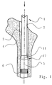
- FIG. 1 shows a schematic representation of a longitudinal section through a bone 4 which has an intramodular bone channel 3 which runs essentially in the direction of its longitudinal axis.
- the filling cannula 2 of a filling device 1 is introduced into this channel 3.
- the free end 11 of the filling cannula 2 is elastically deformable in the radial direction and is pressed against the inner wall of the intramodular bone channel 3 by the filling material 5 emerging from the filling cannula 2.
- the other end of the filling cannula 2 is connected to a dispenser (not shown) for the filling material 5, preferably bone cement, which enters the cannula in the direction of the arrow.
- the collar 7 is stretched radially and the corrugated boundary line 14 takes the form of a circular line, the collar 7 forming a truncated cone (see position A or FIG. 1).
- the strips 8.1 of the second layer are located closely above the strips 8.2 of the first layer and are arranged such that they completely cover the gaps 12 between the strips 8.2.
- the width of the strips 8.1 is chosen so large that the covering of the column 12 is ensured even if the two layers of strips are deflected radially outward under the influence of the filling material, around the annular gap between the inner wall of the bone channel 3 and the free end 11 of the Seal the filling cannula 2 against passage of the filling material.
- the strips 8.1 are fastened to an annular cap 16, which is pushed over the unslit part of the free end 11 of the filling cannula 2 and connected to it by gluing or sufficient static friction. There is also the option (not shown), too to form the second layer of strips directly onto the free end 11 of the filling cannula 2.
- the strips 8.1 and 8.2 consist of the same material as the filling cannula 2, of rubber or a suitable elastic plastic.
- FIGS. 6 and 7 show a further advantageous development of the invention in perspective and as a top view of the material outlet opening 13 in a schematic form.
- the strips 8 are arranged essentially in one layer and are molded onto the annular end face of the free end 11 of the filling cannula 2.
- the strips 8 form elements of the wall of a hollow cylinder and can be moved radially outward with their free end under the action of the filling material.
- the strips 8 are arranged such that the circumferential rear longitudinal edge 10 of one strip projects beyond the front longitudinal edge 9 of the subsequent strip in such a way that a continuous sealing edge 18 is formed in the longitudinal extension of the strip, the strips 8 being essentially tangential with respect to their transverse extension of the circumference of the outlet opening 13 of the filling cannula 2.
Landscapes
- Health & Medical Sciences (AREA)
- Life Sciences & Earth Sciences (AREA)
- Orthopedic Medicine & Surgery (AREA)
- Surgery (AREA)
- Medical Informatics (AREA)
- Engineering & Computer Science (AREA)
- Biomedical Technology (AREA)
- Heart & Thoracic Surgery (AREA)
- Nuclear Medicine, Radiotherapy & Molecular Imaging (AREA)
- Molecular Biology (AREA)
- Animal Behavior & Ethology (AREA)
- General Health & Medical Sciences (AREA)
- Public Health (AREA)
- Veterinary Medicine (AREA)
- Prostheses (AREA)
- Surgical Instruments (AREA)
Abstract
Description
- Die Erfindung betrifft eine Einfüllvorrichtung der im Oberbegriff des Anspruchs 1 angegebenen Art.
- Aus der EP-A2 0 093 560 ist eine Einfüllvorrichtung für Knochenzement in den intramedullären Kanal eines Knochens bekannt. Die Vorrichtung weist eine Kanüle auf, durch die der Knochenzement in den Kanalhohlraum eingebracht werden kann. Zur Stabilisierung der Kanülenposition innerhalb des intramedullären Kanals ist eine aufblasbare Manschette vorgesehen, die den Schaft der Kanüle allseitig umschließt Diese Manschette verhindert gleichzeitig, daß beim Verpressen des Knochenzements am Boden des intramedullären Knochenkanals überschüssiges Material in den an der Kanülenaustrittsöffnung befindlichen Ringraum zwischen der Außenwandung der Kanüle und der Innenwandung des Knochenkanals eindringen kann. Diese ungewünschte Materialbewegung muß insbesondere deshalb unterbunden werden, weil das Eindringen des Knochenzements in den Ringraum oberhalb des Kanülenausganges eine Reduzierung des verfülldruckes zur Folge hätte.
- Die vorstehend beschriebene Lösung weist jedoch den Nachteil auf, daß die Einfüllvorrichtung an ihrem proximalen Ende durch die aufblasbare Dichtung in radialer Richtung erhebliche Abmessungen aufweist. Es ist somit erforderlich, den intramedullären Knochenkanal über das an sich erforderliche Maß hinaus radial zu vergrößern, womit ein zusätzlicher Verlust von gesundem Knochenmaterial verbunden ist. Darüberhinaus ist für die Benutzung der Einfüllvorrichtung Hilfsenergie erforderlich, um die Dichtmanschette mit dem erforderlichen Innendruck zu versehen.
- Weil die bekannte Dichtmanschette auf der Einfüllkanüle verschieblich angeordnet ist, ist die Handhabbarkeit der Einfüllvorrichtung zusätzlich dadurch erschwert, daß die Manschette nicht ohne besonders Übung an den Verfüllpunkt am Ende des intramedullären Knochenkanals positioniert werden kann. Dies ist besonders deshalb ungünstig, da die Höhe der Verfüllung mit Knochenzement nicht exakt festgelegt werden kann. Weiterhin ist nachteilig, daß die Dichtmanschette nach Beendigung der Verfüllung wieder entlüftet werden muß.
- Ausgehend von den Mängeln des Standes der Technik liegt der Erfindung die Aufgabe zugrunde, eine Einfüllvorrichtung der eingangs genannten Gattung zu entwickeln, mit der ohne Hilfsenergie mit einfachen Mitteln eine Verfüllung des Knochenkanals vorgenommen werden kann, ohne daß der eingefüllte Zement an der Kanüle aufsteigt.
- Diese Aufgabe wird mit den kennzeichnenden Merkmalen des Anspruchs 1 gelöst.
- Die Erfindung schließt die Erkenntnis ein, daß ein sicheres Abdichten des Ringraums zwischen der Innenwandung des intramedullären Knochenkanals und der äußeren Wandung im Bereich der Einfüllkanüle, an der sich die Austrittsöffnung für das Verfüllmaterial befindet, auf vorteilhafte Weise dadurch erreicht werden kann, daß der zum Verfüllen des Knochenzements erforderliche Kompressionsdruck gleichzeitig für eine gezielte Deformation einer flexiblen Fortsetzung des freien Endes der Einfüllkanüle genutzt wird, wobei die Kraftübertragung über das Verfüllmaterial selbst erfolgt. Zu diesem Zweck ist das freie Ende der Einfüllkanüle der Einfüllvorrichtung derart ausgebildet, daß unter Einwirkung des Verfüllmaterials eine druckabhängig reversible Verformung desselben erfolgen kann. Gemäß der Erfindung weist die flexible Fortsetzung der Einfüllkanüle eine zu ihrem freien Ende hin zunehmende, durch Überlappung, Elastizität oder Faltung gebildete Materialreserve auf, die trotz Aufspreizens des freien Endes durch den austretenden Knochenzement einen geschlossene Manschette bildet, welche ein Aufsteigen des Knochenzements an der Kanüle verhindert. Durch den sich im Innern der Manschette aufbauenden Druck des Knochenzements legt sich diese dichtend an die Innenwand des Knochenkanals an und hält auf diese Weise einen Überdruck aufrecht, welche den Knochenzement in die Trabekelstruktur preßt, so daß eine innige Verbindung von Zement und Knochenwandung erreicht wird. Insbesondere ist auch das Entstehen von Lufteinschlüssen ausgeschlossen.
- Entsprechend einer bevorzugten Ausführungsform der Erfindung ist das freie Ende der Einfüllkanüle faltenrockähnlich erweitert, wobei gleichzeitig eine Verringerung der Wandstärke in Richtung des Materialaustrags vorgesehen ist. Während des Verfüllens des intramedullären Knochenkanals wird das proximale Ende der Einfüllkanüle durch die Druckwirkung des Verfüllmaterials im wesentlichen in radialer Richtung gedehnt, bis ein Wirkkontakt mit Innenwand des Knochenkanals eingetreten ist. Das freie Ende der Einfüllkanüle weist danach insbesondere die Form eines Kegelstumpfes auf. Durch eine ausreichende Welligkeit der proximalen Abschlußkante der Einfüllkanüle bei gleichzeitig großer Elastizität des verwendeten Materials kann sich der Endbereich der Einfüllkanüle - durch die so gebildete Materialreserve - der Querschnittsveränderung des intramedullären Knochenkanals anpassen und eine ausreichend Abdichtung gewährleisten, wenn die Einfüllkanüle während des Einfüllvorgangs in dem Knochenkanal allmählich nach oben bewegt wird.
- Die erfindungsgemäßen Leitmittel werden bevorzugt einstückig an das Ende der Einfüllkanüle angeformt. Für den Fall, daß der Werkstoff, aus dem die Einfüllkanule gefertigt ist, unter Einsatzbedingungen nur eine geringe Elastizität aufweist, ist entsprechend einer anderen vorteilhaften Weiterbildung der Erfindung an dem freien Ende der Einfüllkanüle die expandierbare Manschette alz zusätzliches Element vorgesehen. Diese kann in Form eines elastischen ringförmigen Elements aufgeklemmt, geklebt oder in sonstiger Weise dichtend verbunden sein.
- Die Manschette besteht vorzugsweise aus Gummi oder einem entsprechenden elastischen Werkstoff und ist am proximalen Ende der Außenfläche der Einfüllkanüle mit dieser durch Kleben verbunden. Diese Verbindungstechnik führt in günstiger Weise zu keiner nennenswerten Vergrößerung des Außendurchmessers der Einfüllkanüle.
- Entsprechend einer anderen günstigen Weiterbildung der Erfindung läuft das proximale Ende der Einfüllkanüle in eine Mehrzahl von Streifenelementenelementen aus. Die Streifenelemente sind im wesentlichen gleichartig ausgebildet und gleichmäßig auf den Umfang der Einfüllkanüle verteilt angeordnet. Sie bilden am freien Ende der Einfüllkanüle einen zylindrischen Rohrstutzen, der in radialer Richtung verformt werden kann. Das Maß der Verformung nimmt dabei in Austrittsrichtung des Verfüllmaterials zu, so daß das proximale Ende der Einfüllkanüle unter Betriebsbedingungen im wesentlichen in eine kegelstumpfartige Konfiguration übergeht. Dabei werden die Außenseiten der Streifenelemente durch das Verfüllmaterial gegen die In-nenwandung des intramedullären Knochenkanals gepreßt und dichten das proximale Ende der Einfüllkanüle in gewünschter Weise gegenüber der Innenwandung des intramodularen Knochenkanals ab.
- Die am proximalen Ende der Einfüllkanüle befindlichen Streifenelemente sind gegebenenfalls einlagig angeordnet, wobei die Kanten der Schmalseiten der Streifenelemente am Umfang der Einfüllkanüle im wesentlichen tangential verlaufend angeordnet sind. Die Längskanten der Streifenelemente überlappen ein-ander jeweils soweit, daß bei der unter Einsatzbedingungen maximal zu erwartenden radialen Verformung eine geschlossene Wandung erhalten bleibt, um das Austreten des Verfüllmaterials in eine unerwünschte Richtung zu verhindern. Der Querschnitt der Anordnung ist dann sägezahnartig.
- Entsprechend einer weiteren günstigen Ausführungsform der Erfindung sind die am proximalen Ende der Einfüllkanüle befindlichen Streifenelemente doppellagig angeordnet. Die Streifenelemente der oberen Lage sind derart angeordnet, daß sie die zwischen den Streifenelementen der unteren Lage befindlichen Spalten überdecken und beim Verpressen des Füllmaterials eine zuverlässige Dichtung gewährleisten, so daß das Verfüllmaterial nur in der vorgesehenen Richtung in den Knochenkanal austreten kann. Bei dieser Anordnung der Streifenelemente ist es in fertigungstechnischer Hinsicht günstig, die erste (untere) Lage von Streifenelementen direkt an das freie Ende der Einfüllkanüle anzuformen und die zweite Streifenelementenlage in Form einer Manschette auf das frei Ende der Einfüllkanüle aufzuschieben und in geeigneter Weise, insbesondere durch Kleben, zu befestigen.
- Andere vorteilhafte Weiterbildungen der Erfindung sind in den Unteransprüchen gekennzeichnet bzw. werden nachstehend zusammen mit der Beschreibung der bevorzugten Ausführung der Erfindung anhand der Figuren näher dargestellt. Es zeigen:
- Figur 1 ein vorteilhaftes Ausführungsbeispiel der Erfindung bei Benutzung im Längsschnitt,
- Figur 2 ein Detail einer ersten Variante der Erfindung in vergrößerter perspektivischer Darstellung,
- Figur 3 das Detail gemäß Figur 2 in der Draufsicht,
- Figur 4 eine andere vorteilhafte Ausführungsform des Details gemäß Figur 3,
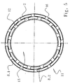
- Figur 5 das Detail gemäß Figur 4 in der Draufsicht,
- Figur 6 eine andere vorteilhafte Ausführungsform des Details gemäß Figur 2, sowie
- Figur 7 das Detail gemäß Figur 6 in der Draufsicht.
- Figur 1 zeigt in schematisierter Darstellung einen Längsschnitt durch einen Knochen 4, der einen im wesentlichen in Richtung seiner Längsachse verlaufenden intramodularen Knochenkanal 3 aufweist. In diesen Kanal 3 ist die Einfüllkanüle 2 einer Einfüllvorrichtung 1 eingebracht. Das freie Ende 11 der Einfüllkanüle 2 ist in radialer Richtung elastisch verformbar und wird durch das aus der Einfüllkanüle 2 austretende Verfüllmaterial 5 gegen die innere Wandung des intramodularen Knochenkanals 3 gepreßt. Dadurch entsteht eine im wesentlichen ringförmige Dichtung 17, die sich stets in der Übergangszone vom verfüllten zum unverfüllten Abschnitt des intramodularen Knochenkanals 3 befindet. Das andere Ende der Einfüllkanüle 2 ist mit einem (nicht dargestellten) Spender für das Verfüllmaterial 5, vorzugsweise Knochenzement, verbunden, welches in Richtung des Pfeils in die Kanüle eintritt.
- Während des Verfüllen wird die Einfüllkanüle langsam zum Eingang des Knochenkanals bewegt, wobei das freie Ende 11 der Kanüle 2 aufgrund seiner radialen Elastizität auch dann eine ausreichende Abdichtung des Ringraumes zwischen Innenwandung des Knochenkanals 3 und der Außenwandung der Einfüllkanüle 2 gewährleistet, wenn der Innendurchmesser des Kanals 3 örtlich variiert.
- Die Abdichtung gewährleistet eine Verpressung des Verfüllmaterials mit großer Dichte und unter Vermeidung von Lufteinschlüssen. Die größe Dichte des verfüllten Knochenzements und die daraus resultierende hohe Festigkeit der sich auf einem Verschlußelement 6 abstützenden Füllung 5, beruht darauf, daß sich der Kompressionsdruck nur über das Verfüllmaterial ausgleichen kann und damit im wesentlichen konstant bleibt. Da der Außendurchmesser des freien Endes der Einfüllkanüle durch seine erfindungsgemäße Ausbildung nur unwesentlich vergrößert wird, ist es nicht erforderlich, den Innendurchmesser des Knochenkanals 3 zusätzlich zu erweitern. Dadurch wird in vorteilhafter Weise vermieden, daß gesundes Knochenmaterial abgetragen werden muß, um den zu behandelnden Knochen entsprechend für die Implantation vorzubereiten.
- Die in Figur 2 perspektivisch und in Figur 3 in Draufsicht auf die Materialaustrittöffnung 13 dargestellte Einfüllkanüle 2 eines Ausführungsbeispiels der erfindungsgemäßen Einfüllvorrichtung für Knochenzement weist ein freies Ende 11 auf, an dem eine faltenrock-ähnliche Manschette 7 vorgesehen ist. Die Manschette 7 ist mit einem ihrer, zylindrischen ausgebildeten Enden 15 auf das freie Ende der Einfüllkanüle 2 aufgeschoben und dort durch Kleben befestigt. Die Manschette besteht aus einem elastischen Gummi und hat im Verhältnis zur Wandstärke der Einfüllkanüle 2 eine relativ geringe Dicke.
- Während des Einfüllvorgangs wird die Manschette 7 radial gedehnt und die gewellte Begrenzungslinie 14 nimmt die Form einer Kreislinie an, wobei die Manschette 7 einen Kegelstumpf bildet (vergleiche Position A oder Figur 1)
- Entsprechend einer nicht dargestellten Weiterbildung der Erfindung ist es günstig, die Manschette 7 direkt an das freie Ende 11 der Einfüllkanüle 2 anzuformen.
- Die Figuren 4 und 5 zeigen in perspektivischer Darstellung und als Draufsicht auf die Materialeinbringöffnung 13 der Einfüllkanüle 2 eine andere vorteilhafte Ausführungsform der Erfindung. Das freie Ende 11 der Einfüllkanüle 2 besteht aus mehreren, gleichartig ausgebildeten Streifen 8.1, 8.2. Die Streifen sind gleichmäßig und symmetrisch am Umfang der Austrittsöffnung 13 der Einfüllkanüle 2in zwei Lagen verteilt angeordnet, wobei sich die einzelnen Streifen parallel zur Mittelachse der Einfüllkanüle 2 erstrecken und die Wandelemente eines doppelwandigen zylindrischen Hohlkörpers bilden. Die Streifen 8.2 der sind an die kreisringförmige Endfläche der Einfüllkanüle 2 angeformt, wobei zwischen den einzelnen Streifen jeweils einen Spalt 12 geringer Breite vorgesehen ist, der sich über die gesamte Länge der Streifen erstreckt.
- Die Streifen 8.1 der zweiten Lage befinden sich dicht über den Streifen 8.2 der ersten Lage und ist derart angeordnet, daß sie die zwischen den Streifen 8.2 bestehenden Spalte 12 vollflächig überdecken. Die Breite der Streifen 8.1 ist so groß gewählt, daß die Bedeckung der Spalte 12 auch dann gewährleistet ist, wenn die beiden Streifenlagen unter Einfluß des Verfüllmaterials radial nach außen ausgelenkt werden, um den Ringspalt zwischen der Innenwandung des Knochenkanals 3 und dem freien Ende 11 der Einfüllkanüle 2 gegen Durchtritt des Verfüllmaterials abzudichten. Die Streifen 8.1 sind an einem ringförmigen Überwurf 16 befestigt, der über den ungeschlitzten Teil des freien Ende 11 der Einfüllkanüle 2 geschoben und mit diesem durch Kleben oder ausreichende Haftreibung verbunden ist. Es besteht ebenso die (nicht dargestellte) Möglichkeit, auch die zweite Streifenlage direkt an das freie Ende 11 der Einfüllkanüle 2 anzuformen. Die Streifen 8.1 und 8.2 bestehen aus dem glöeichen Material wie die Einfüllkanüle 2, aus Gummi oder einem geeignet elastischen Kunststoff.
- In den Figuren 6 und 7 ist eine weitere günstige Weiterbildung der Erfindung perspektivisch und als Draufsicht auf die Materialaustrittsöffnung 13 in schematisierter Form dargestellt. Die Streifen 8 sind im wesentlichen einlagig angeordnet und an die kreisringförmige Stirnfläche des freien Endes 11 der Einfüllkanüle 2 angeformt. Die Streifen 8 bilden Elemente der Wandung eines Hohlzylinders und sind unter Einwirkung des Verfüllmaterials mit ihrem freien Ende radial nach außen beweglich. Die Streifen 8 sind derart angeordnet, daß jeweils die in Umfangsrichtung hintere Längskante 10 eines Streifens die vordere Längskante 9 des nachfolgenden Streifens derart überragt, daß in Längserstreckung der Streifen eine durchgehende Dichtkante 18 gebildet wird, wobei sich die Streifen 8in ihren Querausdehnung im wesentlichen tangential bezüglich des Umfangs der Austrittsöffnung 13 der Einfüllkanüle 2 erstrecken.
- Die Erfindung beschränkt sich in ihrer Ausgestaltung nicht auf die vorstehend angegebenen bevorzugten Ausführungsbeispiele. Vielmehr ist eine Anzahl von Varianten denkbar, welche von der dargestellten Lösung auch bei grundsätzlich anders gearteten Ausführungen Gebrauch macht.
Claims (10)
- Einfüllvorrichtung für das Einbringen von Knochenzement, in den intramedullären Kanal eines Knochens, mit einer Einfüllkanüle und einem Leitmittel zur Führung des Knochenzements beim Austritt aus dem Ende der Kanüle,
dadurch gekennzeichnet,
daß das Leitmittel (7, 8, 8.1, 8.2) als flexible schlauchartige Manschette ausgebildet ist, welche an einem ihrer Enden im Bereich der Austrittsöffnung (13) der Einfüllkanüle (2) dichtend befestigt ist und zum ihrem freien Ende hin zur Anlage an der Innenseite des intramedullären Kanals durch den unter Druck austretenden Knochenzement in radialer Richtung expandierbar ist. - Einfüllvorrichtung nach Anspruch 1, dadurch gekennzeichnet, daß die Verformbarkeit des Leitmittels (7, 8, 8.1, 8.2) in Austrittsrichtung des Verfüllmaterials zunimmt.
- Einfüllvorrichtung nach einem der vorangehenden Ansprüche, dadurch gekennzeichnet, daß das Leitmittel in Austrittsrichtung des Knochenzements lamellenartig geschlitzt oder in anderer Weise segmentiert ausgebildet oder eine in Längsrichtung verlaufende Faltung aufweist, welche eine Flächenreserve zum radialen Expandieren beinhaltet.
- Einfüllvorrichtung nach Anspruch 3, dadurch gekennzeichnet, daß die Segmentierung in Form von in Längsrichtung verlaufenden Streifenelementen ausge-staltet ist.
- Einfüllvorrichtung nach Anspruch 4, dadurch gekennzeichnet, daß die Streifenelemente zwei-oder mehrlagig ausgebildet sind, wobei die Streifenelemente (8.1) der oberen Lage jeweils die zwischen den Streifenelementen (8.2) der unteren Lage befindlichen Stoßkanten bzw. Spalten (12) überdecken.
- Einfüllvorrichtung nach Anspruch 4, dadurch gekennzeichnet, daß sich die maximale Ausdehnung des Querschnitts der Streifenelemente (8) in im wesentlichen tangentialer Richtung der Einfüllkanüle (2) erstreckt.
- Einfüllvorrichtung nach Anspruch 4, dadurch gekennzeichnet, daß die Streifenelemente (8) im wesentlichen einlagig angeordnet sind, wobei jeweils die in Umfangsrichtung hintere Längskante (10) eines Streifenelementess (8) die vordere Längskante (9) des nachfolgenden Streifenelementens mindestens in der Ruhestellung im Querschnitt sägezahnartig überragt.
- Einfüllvorrichtung nach einem der vorangehenden Ansprüche, dadurch gekennzeichnet, daß die Leitmittel aus im wesentlichen dem selben Material bestehen wie die Einfüllkanüle (2) und sich insbesondere einstückig an diese anschließen.
- Einfüllvorrichtung nach einem der vorangehenden Ansprüche, dadurch gekennzeichnet, daß die Leitmittel aus einem Gummimaterial oder aus einem elastischen Kunststoff bestehen.
- Einfüllvorrichtung nach einem der vorangehenden Ansprüche, dadurch gekennzeichnet, daß die Leitmittel (7) am freien Ende (11) der Einfüllkanüle (2) aufgeschoben und/oder durch Kleben befestigt sind.
Applications Claiming Priority (2)
| Application Number | Priority Date | Filing Date | Title |
|---|---|---|---|
| DE4316655 | 1993-05-11 | ||
| DE4316655A DE4316655C2 (de) | 1993-05-11 | 1993-05-11 | Einfüllvorrichtung für Knochenzement |
Publications (2)
| Publication Number | Publication Date |
|---|---|
| EP0628295A1 true EP0628295A1 (de) | 1994-12-14 |
| EP0628295B1 EP0628295B1 (de) | 1999-11-03 |
Family
ID=6488404
Family Applications (1)
| Application Number | Title | Priority Date | Filing Date |
|---|---|---|---|
| EP94250124A Expired - Lifetime EP0628295B1 (de) | 1993-05-11 | 1994-05-11 | Einfüllvorrichtung für Knochenzement |
Country Status (4)
| Country | Link |
|---|---|
| EP (1) | EP0628295B1 (de) |
| AT (1) | ATE186195T1 (de) |
| DE (2) | DE4316655C2 (de) |
| ES (1) | ES2140500T3 (de) |
Cited By (1)
| Publication number | Priority date | Publication date | Assignee | Title |
|---|---|---|---|---|
| EP0872223A1 (de) * | 1997-04-16 | 1998-10-21 | Sulzer Orthopädie AG | Einfüllvorrichtung für Knochenzement |
Citations (7)
| Publication number | Priority date | Publication date | Assignee | Title |
|---|---|---|---|---|
| GB2052267A (en) * | 1979-06-30 | 1981-01-28 | Hardinge K | Medullary canal plug |
| GB2105198A (en) * | 1981-09-04 | 1983-03-23 | William M Murray | Bone cement nozzle |
| EP0093560A2 (de) * | 1982-05-03 | 1983-11-09 | Pfizer Hospital Products Group, Inc. | Verschluss für die Unterdrucksetzung des Zements im intramedullaren Kanal |
| DE8624398U1 (de) * | 1986-09-12 | 1986-10-23 | Joos, Christel, 7000 Stuttgart | Stopfen zum Verschließen einer Körperöffnung |
| US4625722A (en) * | 1985-05-03 | 1986-12-02 | Murray William M | Bone cement system and method |
| WO1990004953A1 (en) * | 1988-11-11 | 1990-05-17 | Magnus Nilsson | Method and apparatus for working bone cement for fixing a prosthesis in a bone |
| EP0428127A1 (de) * | 1989-11-14 | 1991-05-22 | V. Dipl.-Ing. Dr. Med . Jansson | Zementierbare Endoprothese |
-
1993
- 1993-05-11 DE DE4316655A patent/DE4316655C2/de not_active Expired - Lifetime
-
1994
- 1994-05-11 AT AT94250124T patent/ATE186195T1/de not_active IP Right Cessation
- 1994-05-11 EP EP94250124A patent/EP0628295B1/de not_active Expired - Lifetime
- 1994-05-11 ES ES94250124T patent/ES2140500T3/es not_active Expired - Lifetime
- 1994-05-11 DE DE59408872T patent/DE59408872D1/de not_active Expired - Lifetime
Patent Citations (7)
| Publication number | Priority date | Publication date | Assignee | Title |
|---|---|---|---|---|
| GB2052267A (en) * | 1979-06-30 | 1981-01-28 | Hardinge K | Medullary canal plug |
| GB2105198A (en) * | 1981-09-04 | 1983-03-23 | William M Murray | Bone cement nozzle |
| EP0093560A2 (de) * | 1982-05-03 | 1983-11-09 | Pfizer Hospital Products Group, Inc. | Verschluss für die Unterdrucksetzung des Zements im intramedullaren Kanal |
| US4625722A (en) * | 1985-05-03 | 1986-12-02 | Murray William M | Bone cement system and method |
| DE8624398U1 (de) * | 1986-09-12 | 1986-10-23 | Joos, Christel, 7000 Stuttgart | Stopfen zum Verschließen einer Körperöffnung |
| WO1990004953A1 (en) * | 1988-11-11 | 1990-05-17 | Magnus Nilsson | Method and apparatus for working bone cement for fixing a prosthesis in a bone |
| EP0428127A1 (de) * | 1989-11-14 | 1991-05-22 | V. Dipl.-Ing. Dr. Med . Jansson | Zementierbare Endoprothese |
Cited By (2)
| Publication number | Priority date | Publication date | Assignee | Title |
|---|---|---|---|---|
| EP0872223A1 (de) * | 1997-04-16 | 1998-10-21 | Sulzer Orthopädie AG | Einfüllvorrichtung für Knochenzement |
| US5954728A (en) * | 1997-04-16 | 1999-09-21 | Sulzer Orthopaedie Ag | Filling apparatus for bone cement |
Also Published As
| Publication number | Publication date |
|---|---|
| DE4316655C2 (de) | 2003-10-30 |
| ATE186195T1 (de) | 1999-11-15 |
| EP0628295B1 (de) | 1999-11-03 |
| ES2140500T3 (es) | 2000-03-01 |
| DE59408872D1 (de) | 1999-12-09 |
| DE4316655A1 (de) | 1994-11-17 |
Similar Documents
| Publication | Publication Date | Title |
|---|---|---|
| DE3447442C2 (de) | ||
| EP0461474B1 (de) | Ballonkatheter mit Hülse | |
| DE19934154C1 (de) | Abteilvorrichtung für unterteilbares Füllgut in einer flexiblen Schlauchhülle | |
| DE2820181A1 (de) | Verschluss fuer ein laengsgeschlitztes kabelmuffenrohr | |
| DE2329719A1 (de) | Becherfoermige vorrichtung zum auffangen von menstruationsfluessigkeit zur inneren anwendung | |
| EP0720681A1 (de) | Injektionsschlauch für arbeitsfugen an betonbauwerken | |
| DE3817868C2 (de) | Dichtring | |
| EP3150179B1 (de) | Manschette für penisextensionsgeräte | |
| DE2744036C3 (de) | Vorrichtung zum Befestigen einer Dacheindeckungsplatte | |
| DE29822534U1 (de) | Vorrichtung zum Verschließen des Markraums des Femur bei der Implantation von Endoprothesen | |
| DE60107186T2 (de) | Kosmetikbehälter | |
| EP1012417B1 (de) | Verpressschlauch zum herstellen von wasserundurchlässigen oder nur gering wasserdurchlässigen, gasdichten und/oder kraftschlüssigen bauwerksfugen und verfahren zu seiner herstellung | |
| EP0628295B1 (de) | Einfüllvorrichtung für Knochenzement | |
| DE3417882C2 (de) | ||
| EP0018400B1 (de) | Wickelträger mit parallel zu seiner achse verlaufenden tragelementen | |
| DE3515137C2 (de) | ||
| DE19824594C2 (de) | Befestigungselement | |
| DE3203834C2 (de) | Putz-Schutzdeckel aus Kunststoff für Unterputzdosen elektrischer Leitungen | |
| DE29522327U1 (de) | Breitstreckwalze | |
| DE3806971C2 (de) | ||
| EP0901837B1 (de) | Brausekopf mit Reinigungsstiften | |
| DE102020000311B4 (de) | Gerät zum Speichern und Auftragen einer fliessfähigen Substanz, insbesondere einer kosmetischen Substanz | |
| EP0414991B1 (de) | Dichtleiste für die Abdichtung von Fugen bei Gewölbe- oder Tunnelverkleidungselementen | |
| EP1126954B1 (de) | Sprühdose | |
| DE2501359A1 (de) | Venturianordnung |
Legal Events
| Date | Code | Title | Description |
|---|---|---|---|
| PUAI | Public reference made under article 153(3) epc to a published international application that has entered the european phase |
Free format text: ORIGINAL CODE: 0009012 |
|
| AK | Designated contracting states |
Kind code of ref document: A1 Designated state(s): AT BE CH DE DK ES FR GB GR IE IT LI LU MC NL PT SE |
|
| RBV | Designated contracting states (corrected) |
Designated state(s): AT BE CH DE ES FR GB IT LI NL SE |
|
| 17P | Request for examination filed |
Effective date: 19950607 |
|
| 17Q | First examination report despatched |
Effective date: 19970618 |
|
| GRAG | Despatch of communication of intention to grant |
Free format text: ORIGINAL CODE: EPIDOS AGRA |
|
| GRAG | Despatch of communication of intention to grant |
Free format text: ORIGINAL CODE: EPIDOS AGRA |
|
| GRAH | Despatch of communication of intention to grant a patent |
Free format text: ORIGINAL CODE: EPIDOS IGRA |
|
| GRAH | Despatch of communication of intention to grant a patent |
Free format text: ORIGINAL CODE: EPIDOS IGRA |
|
| GRAA | (expected) grant |
Free format text: ORIGINAL CODE: 0009210 |
|
| AK | Designated contracting states |
Kind code of ref document: B1 Designated state(s): AT BE CH DE ES FR GB IT LI NL SE |
|
| PG25 | Lapsed in a contracting state [announced via postgrant information from national office to epo] |
Ref country code: SE Free format text: THE PATENT HAS BEEN ANNULLED BY A DECISION OF A NATIONAL AUTHORITY Effective date: 19991103 Ref country code: NL Free format text: LAPSE BECAUSE OF FAILURE TO SUBMIT A TRANSLATION OF THE DESCRIPTION OR TO PAY THE FEE WITHIN THE PRESCRIBED TIME-LIMIT Effective date: 19991103 |
|
| REF | Corresponds to: |
Ref document number: 186195 Country of ref document: AT Date of ref document: 19991115 Kind code of ref document: T |
|
| REG | Reference to a national code |
Ref country code: CH Ref legal event code: EP |
|
| REF | Corresponds to: |
Ref document number: 59408872 Country of ref document: DE Date of ref document: 19991209 |
|
| RAP2 | Party data changed (patent owner data changed or rights of a patent transferred) |
Owner name: BIOMET MERCK DEUTSCHLAND GMBH |
|
| ITF | It: translation for a ep patent filed | ||
| NLT2 | Nl: modifications (of names), taken from the european patent patent bulletin |
Owner name: BIOMET MERCK DEUTSCHLAND GMBH |
|
| REG | Reference to a national code |
Ref country code: ES Ref legal event code: FG2A Ref document number: 2140500 Country of ref document: ES Kind code of ref document: T3 |
|
| ET | Fr: translation filed | ||
| GBT | Gb: translation of ep patent filed (gb section 77(6)(a)/1977) |
Effective date: 20000228 |
|
| NLV1 | Nl: lapsed or annulled due to failure to fulfill the requirements of art. 29p and 29m of the patents act | ||
| REG | Reference to a national code |
Ref country code: GB Ref legal event code: 732E |
|
| PG25 | Lapsed in a contracting state [announced via postgrant information from national office to epo] |
Ref country code: AT Free format text: LAPSE BECAUSE OF NON-PAYMENT OF DUE FEES Effective date: 20000511 |
|
| PG25 | Lapsed in a contracting state [announced via postgrant information from national office to epo] |
Ref country code: LI Free format text: LAPSE BECAUSE OF NON-PAYMENT OF DUE FEES Effective date: 20000531 Ref country code: CH Free format text: LAPSE BECAUSE OF NON-PAYMENT OF DUE FEES Effective date: 20000531 Ref country code: BE Free format text: LAPSE BECAUSE OF NON-PAYMENT OF DUE FEES Effective date: 20000531 |
|
| PLBE | No opposition filed within time limit |
Free format text: ORIGINAL CODE: 0009261 |
|
| STAA | Information on the status of an ep patent application or granted ep patent |
Free format text: STATUS: NO OPPOSITION FILED WITHIN TIME LIMIT |
|
| 26N | No opposition filed | ||
| BERE | Be: lapsed |
Owner name: ARTOS MEDIZINISCHE PRODUKTE G.M.B.H. Effective date: 20000531 |
|
| REG | Reference to a national code |
Ref country code: CH Ref legal event code: PL |
|
| REG | Reference to a national code |
Ref country code: GB Ref legal event code: IF02 |
|
| PGFP | Annual fee paid to national office [announced via postgrant information from national office to epo] |
Ref country code: DE Payment date: 20120417 Year of fee payment: 19 |
|
| PGFP | Annual fee paid to national office [announced via postgrant information from national office to epo] |
Ref country code: GB Payment date: 20120522 Year of fee payment: 19 Ref country code: FR Payment date: 20120601 Year of fee payment: 19 |
|
| PGFP | Annual fee paid to national office [announced via postgrant information from national office to epo] |
Ref country code: IT Payment date: 20120529 Year of fee payment: 19 |
|
| PGFP | Annual fee paid to national office [announced via postgrant information from national office to epo] |
Ref country code: ES Payment date: 20120525 Year of fee payment: 19 |
|
| GBPC | Gb: european patent ceased through non-payment of renewal fee |
Effective date: 20130511 |
|
| PG25 | Lapsed in a contracting state [announced via postgrant information from national office to epo] |
Ref country code: DE Free format text: LAPSE BECAUSE OF NON-PAYMENT OF DUE FEES Effective date: 20131203 |
|
| PG25 | Lapsed in a contracting state [announced via postgrant information from national office to epo] |
Ref country code: IT Free format text: LAPSE BECAUSE OF NON-PAYMENT OF DUE FEES Effective date: 20130511 |
|
| REG | Reference to a national code |
Ref country code: FR Ref legal event code: ST Effective date: 20140131 |
|
| PG25 | Lapsed in a contracting state [announced via postgrant information from national office to epo] |
Ref country code: GB Free format text: LAPSE BECAUSE OF NON-PAYMENT OF DUE FEES Effective date: 20130511 |
|
| REG | Reference to a national code |
Ref country code: DE Ref legal event code: R119 Ref document number: 59408872 Country of ref document: DE Effective date: 20131203 |
|
| PG25 | Lapsed in a contracting state [announced via postgrant information from national office to epo] |
Ref country code: FR Free format text: LAPSE BECAUSE OF NON-PAYMENT OF DUE FEES Effective date: 20130531 |
|
| REG | Reference to a national code |
Ref country code: ES Ref legal event code: FD2A Effective date: 20140606 |
|
| PG25 | Lapsed in a contracting state [announced via postgrant information from national office to epo] |
Ref country code: ES Free format text: LAPSE BECAUSE OF NON-PAYMENT OF DUE FEES Effective date: 20130512 |