EP0628339B1 - Method for extraction of undesirable substances in a biogas - Google Patents
Method for extraction of undesirable substances in a biogas Download PDFInfo
- Publication number
- EP0628339B1 EP0628339B1 EP94109124A EP94109124A EP0628339B1 EP 0628339 B1 EP0628339 B1 EP 0628339B1 EP 94109124 A EP94109124 A EP 94109124A EP 94109124 A EP94109124 A EP 94109124A EP 0628339 B1 EP0628339 B1 EP 0628339B1
- Authority
- EP
- European Patent Office
- Prior art keywords
- biogas
- gas
- carbon dioxide
- process step
- nitrogen
- Prior art date
- Legal status (The legal status is an assumption and is not a legal conclusion. Google has not performed a legal analysis and makes no representation as to the accuracy of the status listed.)
- Expired - Lifetime
Links
Images


Classifications
-
- C—CHEMISTRY; METALLURGY
- C10—PETROLEUM, GAS OR COKE INDUSTRIES; TECHNICAL GASES CONTAINING CARBON MONOXIDE; FUELS; LUBRICANTS; PEAT
- C10L—FUELS NOT OTHERWISE PROVIDED FOR; NATURAL GAS; SYNTHETIC NATURAL GAS OBTAINED BY PROCESSES NOT COVERED BY SUBCLASSES C10G OR C10K; LIQUIFIED PETROLEUM GAS; USE OF ADDITIVES TO FUELS OR FIRES; FIRE-LIGHTERS
- C10L3/00—Gaseous fuels; Natural gas; Synthetic natural gas obtained by processes not covered by subclass C10G, C10K; Liquefied petroleum gas
- C10L3/06—Natural gas; Synthetic natural gas obtained by processes not covered by C10G, C10K3/02 or C10K3/04
- C10L3/10—Working-up natural gas or synthetic natural gas
-
- B—PERFORMING OPERATIONS; TRANSPORTING
- B01—PHYSICAL OR CHEMICAL PROCESSES OR APPARATUS IN GENERAL
- B01D—SEPARATION
- B01D53/00—Separation of gases or vapours; Recovering vapours of volatile solvents from gases; Chemical or biological purification of waste gases, e.g. engine exhaust gases, smoke, fumes, flue gases, aerosols
- B01D53/34—Chemical or biological purification of waste gases
- B01D53/46—Removing components of defined structure
- B01D53/48—Sulfur compounds
- B01D53/52—Hydrogen sulfide
-
- B—PERFORMING OPERATIONS; TRANSPORTING
- B01—PHYSICAL OR CHEMICAL PROCESSES OR APPARATUS IN GENERAL
- B01D—SEPARATION
- B01D53/00—Separation of gases or vapours; Recovering vapours of volatile solvents from gases; Chemical or biological purification of waste gases, e.g. engine exhaust gases, smoke, fumes, flue gases, aerosols
- B01D53/34—Chemical or biological purification of waste gases
- B01D53/46—Removing components of defined structure
- B01D53/54—Nitrogen compounds
- B01D53/58—Ammonia
-
- B—PERFORMING OPERATIONS; TRANSPORTING
- B01—PHYSICAL OR CHEMICAL PROCESSES OR APPARATUS IN GENERAL
- B01D—SEPARATION
- B01D53/00—Separation of gases or vapours; Recovering vapours of volatile solvents from gases; Chemical or biological purification of waste gases, e.g. engine exhaust gases, smoke, fumes, flue gases, aerosols
- B01D53/34—Chemical or biological purification of waste gases
- B01D53/46—Removing components of defined structure
- B01D53/62—Carbon oxides
-
- B—PERFORMING OPERATIONS; TRANSPORTING
- B01—PHYSICAL OR CHEMICAL PROCESSES OR APPARATUS IN GENERAL
- B01D—SEPARATION
- B01D53/00—Separation of gases or vapours; Recovering vapours of volatile solvents from gases; Chemical or biological purification of waste gases, e.g. engine exhaust gases, smoke, fumes, flue gases, aerosols
- B01D53/34—Chemical or biological purification of waste gases
- B01D53/74—General processes for purification of waste gases; Apparatus or devices specially adapted therefor
- B01D53/75—Multi-step processes
-
- Y—GENERAL TAGGING OF NEW TECHNOLOGICAL DEVELOPMENTS; GENERAL TAGGING OF CROSS-SECTIONAL TECHNOLOGIES SPANNING OVER SEVERAL SECTIONS OF THE IPC; TECHNICAL SUBJECTS COVERED BY FORMER USPC CROSS-REFERENCE ART COLLECTIONS [XRACs] AND DIGESTS
- Y02—TECHNOLOGIES OR APPLICATIONS FOR MITIGATION OR ADAPTATION AGAINST CLIMATE CHANGE
- Y02C—CAPTURE, STORAGE, SEQUESTRATION OR DISPOSAL OF GREENHOUSE GASES [GHG]
- Y02C20/00—Capture or disposal of greenhouse gases
- Y02C20/40—Capture or disposal of greenhouse gases of CO2
-
- Y—GENERAL TAGGING OF NEW TECHNOLOGICAL DEVELOPMENTS; GENERAL TAGGING OF CROSS-SECTIONAL TECHNOLOGIES SPANNING OVER SEVERAL SECTIONS OF THE IPC; TECHNICAL SUBJECTS COVERED BY FORMER USPC CROSS-REFERENCE ART COLLECTIONS [XRACs] AND DIGESTS
- Y02—TECHNOLOGIES OR APPLICATIONS FOR MITIGATION OR ADAPTATION AGAINST CLIMATE CHANGE
- Y02P—CLIMATE CHANGE MITIGATION TECHNOLOGIES IN THE PRODUCTION OR PROCESSING OF GOODS
- Y02P20/00—Technologies relating to chemical industry
- Y02P20/151—Reduction of greenhouse gas [GHG] emissions, e.g. CO2
Definitions
- the present invention relates to a method of removing from a biogas carbon dioxide and sulphur and nitrogen containing compounds originating from anaerobic decomposition of biological material.
- DE-A-424,596 uses low concentrations of formalin which, combined with said metallic salts, shifts the balance of the ammonium carbonate in the manure on one hand towards ammonium chloride and on the other hand towards calcium- or magnesium carbonate , both of which are precipitated, and the ammonia is bound in an ammonium form which is free of smell and no longer volatile.
- the amount of formalin binds ammonia as a water-soluble product NH 2 CH 2 OH analogously with DE-A-3,412,581.
- GB-A-673,187 and GB-A-879,112 do not describe a regenerating method of removing hydrogen sulphide, but rather use of an iron(II)sulphate in an alcaline solution for the formation of iron(III).
- DE-C-1,050,013 and US -A-2,641,526 both use a ferric oxy compound which may be regenerated by means of adding air, whereby sulphur is precipitated simultaneously.
- EP-A-0 084 669 discloses a method of purifying a gas containing dust from a urea plant, in order to obtain removal of ammonia and other decomposition products of urea, wherein the gas is treated in an aqueous washing solution containing formaline.
- EP-A-0 280 750 discloses a method of removing hydrogen sulphide from a gas comprising the steps of 1) effecting a microbial conversion of FeSO 4 to Fe 2 (SO 4 ) 3 , 2) bringing the gas in contact with an aqueous solution of the Fe 2 (SO 4 ) 3 formed to form FeSO 4 , H 2 SO 4 and S, 3) separating the elemental sulphur formed, and 4) recirculating the FeSO 4 formed to step 1).
- EP-A-0 377 476 discloses a method of removing ammonia from a gas, e.g. a gas originating from a boiindustial process, such as composting, wherein the gas is treated in an aqueous solution containing an acid, such as phophoric, hydrochloric, nitric or sulphuric acid, to form a salt, which is industrially reusable.
- a gas e.g. a gas originating from a boiindustial process, such as composting
- an acid such as phophoric, hydrochloric, nitric or sulphuric acid
- US-A-4 356 155 discloses a method of removing hydrogen sulphide from a gas, wherein the gas is treated in an aqueous solution of Fe(III)chelate of nitrilotriacetic acid to form crystalline sulphur.
- the technical problem addressed by the invention is to provide a method of converting a biogas into a gas consisting essentially of methane and having such a reduced content of impurities that it corresponds to natural gas for all practical purposes and may be used as such.
- three types of compounds are removed from the biogas, 1) carbon dioxide, 2) nitrogen-containing compounds, primarily amines, mainly ammonia, and 3) sulphur-containing compounds, mainly hydrogen sulphide.
- the invention is based on the recognition that the above stated technical problem may be solved by removing from the gas the said three types of compounds, and that this removal may be effected by using a combination of the reaction means (i)-(iv) outlined in claim 1.
- ammonia or other nitrogen compounds present e.g. in animal manure, waste water or other highly polluted liquids by performing a so-called ammonium stripping followed by the use of the method according to the present invention.
- ammonia together with other volative gases, may be converted into useful fertilizers in such a manner that the ammoinium evaporation is completely eliminated.
- the resulting precipitate fertilizers are particularly valuable compared to ordinary water-soluble fertilizers which are more or less liable to be washed out.
- the method is particularly useful for biogas since today there is no simple and economical way of purifying biogas so that one obtains the quality of natural gas, i.e. the biogas being purified of mercaptans, hydrogen sulphide, amines, ammonia and carbon dioxide so that the remaining product will be pure methane.
- the known methods of purifying biogas all operate primarily with physical parameters such as changing pressure and temperature, which may, however, be followed by a subsequent chemical treatment for purification and separation of the condensed products, such as described in GB-A-692,804 and GB-A-734,577.
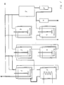
- Fig. 1 shows a flow diagram of the method according to the invention.
- the diagram comprises a first, second, third and fourth process step 1, 2, 3 and 4.
- the diagram comprises two additional process steps 5 and 6 wherein end products are extracted.
- the diagram also comprises a seventh process step 7 wherein the gas may be burned, an eighth process step 8 wherein waste gas is dehydrated, and a ninth process step 9 comprising an oven.
- each of the process steps 1, 2, 3, 4 and 6 there is provided a stirrer and a sieve or a filter for distribution of the substances added in the process steps.
- a heat exchanger is provided so that it is possible to add or remove heat from the process.
- the process steps are connected with each other as indicated by lines between the individual steps. Whether the lines are bold or thin depends on whether the gas is treated in all or just a few process steps. Valves between the individual process steps are illustrated by circles on the lines.
- Fig. 1 the gas is treated in the following process steps as illustrated by the shown flow diagram.
- the gas contains nitrogen compounds NR 1 R 2 R 3 and sulphurous compounds, SR 1 R 2 .
- the nitrogen and sulphurous compounds may be e.g. ammonia, NH 3 , and hydrogen sulphide, H 2 S, respectively, which two substances will be used in the following as a basis for the description of the individual process steps.
- the gas is led through a valve to the first process step containing an aqueous solution of either an aldehyde, a ketone, organic acids or acid chlorides, phosphate ions, metallic ions or an acid, e.g. phosphoric acid, H 3 PO 4 , or a mixture of these substances.
- an aqueous solution of either an aldehyde, a ketone, organic acids or acid chlorides, phosphate ions, metallic ions or an acid, e.g. phosphoric acid, H 3 PO 4 , or a mixture of these substances.
- the aqueous solution used will be a solution of formaldehyde, H 2 CO.
- the gas is bubbled through the aqueous solution while the latter is being stirred.
- Hexamethylene tetramine, C 6 H 12 N 4 , and trithio formaldehyde, C 3 H 6 S 3 are transferred to process step 5.
- the aqueous reaction solution is precipitated at low-temperature heating and under reduced pressure. Small amounts of thio compounds are removed through reaction with formaline. If one of the radicals in SR 1 R 2 is constituted by anything but hydrogen, H, the following reaction will take place between the sulphurous compound and the aqueous solution of formaldehyde: R 1 SH + H 2 CO ⁇ R 1 SCH 2 OH or (R 1 S) 2 CHOH
- Process step 4 contains an aqueous solution of a metallic salt, preferably Fe 2 SO 4 (NO) 2 whereby metallic nitrogen oxide salt is formed in a chemical process. This salt may be heated and recirculated.
- a metallic salt preferably Fe 2 SO 4 (NO) 2 whereby metallic nitrogen oxide salt is formed in a chemical process. This salt may be heated and recirculated.
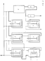
- Fig. 2 shows a second flow of a process according to the invention.
- the gas has a high content of sulphurous compounds, SR 1 R 2 , and carbon dioxide, CO 2 .
- the contents of nitrogen compounds, NR 1 R 2 R 3 is insignificantly small.
- H 2 S will be used as a basis for the sulphurous compound.
- the gas is firstly treated in process step 2. If nitrogen compounds are present in the gas, it must first be treated in process step 1 in order to remove these compounds which would otherwise accumulate in process step 2.
- Process step 2 contains an aqueous solution of ferric oxyhydroxyde, FeO(OH), and the gas containing H 2 S will react with ferric oxyhydroxyde, resulting in the following reactions: 3 H 2 S + 2 Fe 3+ + 3 OH - ⁇ Fe 2 S 3 + 3 H + + 3 H 2 O 2 Fe 2 S 3 + 3 O 2 + 2 H 2 O ⁇ 4 FeO(OH) + 6 S
- the precipitated ferric sulphide, Fe 2 S 3 is led to process step 6 where atmospheric air is bubbled under stirring whereby ferric sulphide is oxidized into ferric oxyhydroxyde, FeO(OH), during liberation of free sulphur, S, as stated in the second equation.
- the ferric oxyhydroxyde is recycled to process step 2 and the process is repeated.
- pH is adjusted by adding suitable chemical means. pH should preferably be between 5 and 8.
- NR 1 R 2 R 3 e.g. ammonia NH 3
- the ammonia will react with the ferric oxyhydroxyde, FeO(OH), resulting in the following reactions: Fe 3+ + 3 NH 3 + 3 H 2 O ⁇ Fe(OH) 3 + 3 NH 4 + Fe(OH) 3 ⁇ FeO(OH) + H 2 O
- the gas is now free of undesirable, malodorous and poisonous substances and may be led to process step 3 for removal of CO 2 .
- Removal of CO 2 in process step 3 is accomplished by bubbling the gas while stirring with a chemically active solution of a suitable precipitation means, which is added to the process continuously.
- a chemically active solution of a suitable precipitation means which is added to the process continuously.
- process step 3 contains a metallic chloride as chemically active means, it will be consumed by bubbling with CO 2 during formation of metallic hydrogen carbonate, metal(HCO 3 ) y , which is precipitated and removed from the process.
- the following reactions will happen, capital M signifying a metal: MCl y + y CO 2 + y NH 3 + y H 2 O ⁇ M(HCO 3 ) y + y NH 4 Cl M(OH) y + y NH 4 Cl ⁇ MCl y + y NH 3 + y H 2 O
- ammonium chloride NH 4 Cl
- a base such as metallic hydroxyde, M(OH) y
- ammonia and metallic carbonate may be used for adjusting pH in process 2.
- Removal of carbon dioxide, CO 2 is a cyclical process and requires no continuous addition of ammonia, NH 3 .
- the gas After the gas has been treated in process step 2 and process step 3, it is free of sulphurous compounds and of CO 2 . Afterwards the gas may optionally be led to process step 7 for burning. After burning the waste gas will only contain carbon dioxide, CO 2 , and water, H 2 O, as the acid oxides have been removed from the gas prior to the burning.
- the process may be performed with many different types of biological fuel, e.g. straw. If the waste gas contains compounds comprising NO x , e.g. caused by a high burning temperature, these may be removed by first dehydrating the gas in process step 8 and then leading it to one of the following processes:
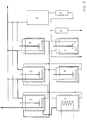
- Fig. 3 shows another flow diagram for a method according to the invention.
- the gas contains a large share of nitrogen compounds, NR 1 R 2 R 3 and a low content of sulphurous compounds, SR 1 R 2 .
- the gas is led to process step 1 where the nitrogen compounds are removed by reaction with metal(II)hydrogen phosphate, MHPO 4 , whereby metal(II)ammonium phosphate, NH 4 MPO 4 , is formed.
- the moll relationship between ammonia, metal (II) and phosphate may be 1:1:1, 2:1:2 or 4:1:2, respectively.
- the formed metal(II)ammonium phosphate may, by heating or by chemical treatment, be caused to liberate ammonia, NH 3 , which may be used in process step 3 for the removal of carbon dioxide, CO 2 . Excessive metal(II)hydrogen phosphate may be recirculated to process step 1 for repeated reaction with ammonia or amines.
- process step 2 contains metal(III)oxyhydroxide, MO(OH).
- MO(OH) metal(III)oxyhydroxide
- SR 1 R 2 sulphurous compounds
- M 2 S 3 metal(III)sulphide
- H 2 S will be used as a basis for SR 1 R 2
- ferric oxyhydroxide, FeO(OH) will be used as a basis for metal(III)oxyhydroxide
- Fe 2 S 3 will be used as a basis for metallic (III) sulphide.
- Fe 2 S 3 may be reformed into ferric oxyhydroxide, FeO(OH), and free sulphur, S, during the following reactions: 3 H 2 S + 2 Fe 3+ + 3 OH - ⁇ Fe 2 S 3 + 3 H + + 3 H 2 O 2 Fe 2 S 3 + 3 O 2 + 2 H 2 O ⁇ 4 FeO(OH) + 6 S
- the sulphur is removed from the surface of the aqueous phase or by means of centrifugation. After regeneration, the water containing ferric oxyhydroxide, FeO(OH), is led back to process step 2, whereupon the process is repeated.
- the gas is led on to process step 3 for removal of CO 2 as described in the text of Fig. 2. If removal of CO 2 is not desired, the gas is led directly to process step 7, alternatively directly to the recipient.
- the process step contains an aqueous solution of formaldehyde, H 2 CO, whereby the contents of ammonia, NH 3 , and hydrogen sulphide, H 2 S, in the gas are removed.
- the composition of the gas prior to treatment is as follows:
- composition of the gas after treatment is as follows:
- biogas is not led through process step 2 as H 2 S has been removed by 99.99%. Whether carbon dioxide CO 2 is removed, depends on whether it is profitable in respect of the difference in sales price existing for biogas with and without carbon dioxide, respectively.
- Waste water from a fish plant is stripped, e.g. by ventilation, whereby the volatile compounds are driven off the waste water.
- the resulting gas with the volatile compounds is led to process step 2 where the gas is bubbled through a solution containing ferric oxyhydroxyde, FeO(OH).
- ferric sulphides Fe 2 S 3
- Fe 2 S 3 ferric sulphides
- process step 2 takes place at a temperature of approx. 50°C, and if atmospheric air is added simultaneously, the nitrogen compounds will be driven off and they are subsequently led from process step 2 to process step 1.
- Phosphoric acid, H 3 PO 4 is added in process step 1.
- calcium carbonate, CaCO 3 is added for adjustment of pH to approx. 7.5. Then a phosphate compound will be precipitated, having the following composition: (NR 1 R 2 R 3 ) 2 Ca(HPO 4 ) 2 , 2 H 2 O
- N, P and Ca, respectively, in the precipitated substances confirms the structure.
- a measure of N and P prior to the addition of calcium carbonate is necessary in order to establish the correct stoichiometric relationship between N and P and calcium carbonate, respectively.
- Other metallic ions than calcium e.g. potassium K or magnesium Mg, may be added; it is merely a question of price and of the micro nutrient the finished fertilizer is supposed to contain. If for example magnesium carbonate is used, there is a possibility of a mixture of precipitated metallic phosphates:
- the waste water is free of malodorous substances, and an analysis shows a reduction of NR 1 R 2 R 3 and SR 1 R 2 of between 98% and 99.9%.
- Manure either degassed in order to reduce excess ammonia or not, is subjected to ammonia stripping. After the stripping, the manure is free of most of the nitrogen compounds and therefore, usually on exemption, it may be spread on suitable areas.
- the stripped ammonia is of approximately 30%, which is an increase of the concentration from approximately 0.4% in the raw manure.
- the stripping is preferably accomplished by adding metalphosphate to the manure whereby metalammonium phosphate is precipitated.
- the precipitated metalammonium phosphate is subjected to a chemical or thermal treatment by addition of base or by heating, whereby the ammonia is liberated in a gaseous form.
- metalphosphate ions are precipitated which may be recirculated in the stripping process, or which may be reused in process step 1 according to the present invention.
- the stripped ammonia is treated by the method according to the invention.
- a crystalline substance e.g. in the form of C 6 H 12 N 4 , (NH 4 ) 2 M(HPO 4 ) 2 or NH 4 MPO 4 . This leaves a remaining concentration of the stripped 30% ammonia of 0.1 - 10 ppm.
- fertilizer precipitate depends on local conditions, including the possibility of buying phosphor. If the option of buying phosphor is available, ammonia from the manure stripping is treated in process step 1 with phosphate by addition of acid in the form of phosphorous acid or by addition of other phosphate substances such as metal(II)hydrophosphate. If there is excess phosphor in the area where the fertilizer precipitate is to be spread, one may add formaldehyde in process step 1 so that a non-phosphate precipitate is precipitated.
- the ammonium chloride solution may be led to process 1 and is processed in process step 2 or as non-phosphate fertilizer precipitate.
- a mixture of divalent metallic ions may advantageously be used for precipitation of amines such as ammonia and ammonium ions as considerably lower concentrations of nitrogen and phosphor will remain at a lower pH than if the metal alone were present in the solution.
- the waste gas may contain acid oxides such as NO x , which may be removed as described in Fig. 2.
- Ni x is added to a 50% solution of ferrous sulphate in concentrated sulphurous acid by bubbling through the solution under simultaneous stirring.
- FeSO 4 NO is precipitated at process step 4.
- the precipitated FeSO 4 NO may be recycled under liberation of nitrogen oxide, which reacts with the oxygen of the air under formation of nitrogen dioxide, NO 2 , which, through reaction with water, is transformed into fertilizers in the following reactions: 2 FeSO 4 NO + O 2 ⁇ 2 FeSO 4 + 2 NO 2 2 NO 2 + H 2 O ⁇ HNO 3 + HNO 2
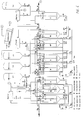
- Fig. 4 illustrates a first embodiment of a process plant for use by the method according to the invention.
- the reaction speed is increased approximately 10 times by adding sodium hydroxide.
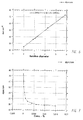
- the change of the surface tension increases the speed approximately 3 times, see Fig. 6.
- the result has appeared by keeping the pressure, the temperature and the rate of flow constant through a chemically active solution.
- the biogas may contain traces of ammonia small amounts of NH 2 CH 2 OH and (CH 2 ) 6 N 4 may be formed when the biogas is bubbled through the chemically active solution.
- An increase of the hydroxide ion concentration accelerates the process further and reduces the solubility of methane in the formalin, and restrains simultaneously the forming of (CH 2 ) 6 N 4 .
- Fig. 7 shows the surface tension as a function of the concentration of the surface-active agent.
- the biogas is at the bottom pumped into a tank A* and the gas is dispersed in small bubbles through a diffuser in such a way that the surface of the gas is as large as possible. Simultaneously with the biogas-bubbles upward direction, these are met by a downward water current consisting of the chemical active solution. By using said procedure the contact time of the biogas with the chemical active solution is increased.
- tank A* When the concentration of formalin in tank A* is below a specified level a valve is closed and the biogas is led to tank A.
- the tank A contains the same chemical active solution as tank A* and the cleaning process is continued in tank A as in tank A*.
- the solution in tank A* with the formed cyclic trimer (C 3 H 6 S 3 ) is pumped into the reaction tank A2.
- the tank A3 contains the same dissolved chemicals which are/were present in tank A*.
- the purpose of pumping liquid from tank A3 into tank A*, so that the latter is completely full, serves as certainty that all the biogas is removed from A* before the resultant liquid is transferred to A2 during air intake in tank A*. Hereby the danger of explosion is avoided.
- tank A* When the whole amount in tank A* is transferred into tank A2 the latter is heated to a temperature of 55°C and the pressure is reduced to 0.5 atm. of pressure. Water is distilled off to approximately half volume. The remaining part of the liquid containing the cyclic trimer (C 3 H 6 S 3 ) is pumped to a strain, where the cyclic trimer (C 3 H 6 S 3 ) is separated from the chemical active solution, which is led back into tank A*, where the equivalent amount of formalin is added, corresponding to the cyclic trimer (C 3 H 6 S 3 ) removed from the solution. The distillate from A2 is led back into tank A*. A* is now once more ready for biogas cleaning.
- the biogas When the biogas has passed A* and the hydrogen sulphide is removed, the biogas is pumped into tank B* where the gas is pressed through a diffuser to obtain a surface as large as possible.
- the upward bubbles meet a strong counter-current of a chemical active solution, which increases the contact time between the carbon dioxide of the biogas and the solution.
- the aqueous solution consists primarily of ammonia and an inorganic salt where the cation may be mono- or bivalent.
- the anion may be halogen, sulphate or phosphate.
- the speed with which the carbon dioxide may be removed from the biogas is partly dependent on the biogas speed through the solution, the diameter of the biogas bubbles and the speed with which the carbon dioxide reacts with the chemically active solution. Physical parameters such as pressure and temperature obviously also have an influence on the reaction speed.
- Fig. 6 shows the diameters of the bubbles are directly proportional to the surface tension of the chemically active solution. Simultaneously, it is shown that the removal of the carbon dioxide follows the bubble diameter for the biogas, Fig. 8. It means that the reaction speed between the carbon dioxide and the chemically active solution is increased. As shown in Fig. 9 the removal of carbon dioxide is inversely proportional to the surface tension, which is of great importance for the biogas flow through the plant and accordingly for the size of the plant.
- Fig. 9 is produced in such a way that 100% CO 2 represents a certain biogas flow through the chemically active solution where the carbon dioxide of the biogas is removed.
- the biogas flow is increased in such a way that the carbon dioxide of the biogas just is removed. 200% CO 2 are equivalent to a doubling of the biogas flow.
- the tanks B* and B2* work at the same time, i.e. after the biogas has left B* it is pumped into B2* in which the same process is repeated as in B*, as it is the same chemically active solutions.
- Two tanks are used of practical reasons.
- the chemically active solution in e.g. tank B* is consumed (i.e. the carbon dioxide is precipitated as a sparingly soluble carbonate)
- the whole content of the tank is pumped to a strain where the sparingly soluble carbonate is removed and the liquid is led back to tank B* for regeneration and adjusting by adding new chemicals so that the process may be repeated.
- Tank B2* undergoes the same procedure as tank B*.
- Tank B* is processed more often than tank B2* as the majority of the carbon dioxide is removed by passage of the first tank B*.
- Tank B3 pumps water into tank B* as well as into tank B2* in order to prevent forming of methane pockets in the tanks before the pumping out of the resulting chemically active liquids for cleaning, regeneration and adjusting. While said cleaning procedure, regeneration and adjusting has taken place for the tanks B* and B2* the biogas is led to the tanks B and B2 for the removal of carbon dioxide.
- these tanks (B and B2) have reacted completely, i.e. the precipitate material is used, they undergo the same procedure as for the tanks B* and B2*.
- a constant measuring of ammonia and carbon dioxide in the tanks B*,B2*,B and B2 takes care that the concentration in the chemically active solutions all the time are at a maximum, which simultaneously reduces the solubility of the methane in the liquids.
- the sparingly soluble carbonate is regenerated in the heater and is transferred to silo 3 in order to be re-used in the process as a base (metaloxide).
- Silo 1 contains ammonia (alkali) and silo 2 metalsalt, e.g. CaCl 2 , MgCl 2 , NaCl etc.
- CaCl 2 is used.
- the biogas is now free of hydrogen sulphide, ammonia and carbon dioxide, but because of the volatility of ammonia the methane contains small amounts of ammonia from the tanks (B*,B,B2* and B2) which are removed in tank C.
- Tank C contains phosphoric acid by which the ammonia is catched.
- a sparingly soluble double salt (NH 4 ) 2 Ca(HPO 4 ) 2 ,H 2 O is precipitated, at a pH value between 5.2 and 8.0.
- process step C may run continuously with a constant removal of the precipitated diammonium-calcium-diphosphate.
- diammonium-calcium-diphosphate has great interest, as the crops grow surprisingly better than a corresponding fertilizer with the same content of nitrogen and phosphor in percentages. If magnesium oxide had been used as a base, the corresponding diammonium-magnesium-diphosphate would have been precipitated with the same interesting fertilizing effect as described above. Mixing of the bases is also possible as the fertilizer product thereby changes the water-solubility.
- the biogas is now converted into pure methane and nay be led on to a natural gas system. All process steps for the whole system are measured and automatically controlled by PLC.
- the plant is controlled on the basis of the following measurements: hydrogen sulphide, carbon dioxide, ammonia, water, nitrogen and methane and the pH value, conductivity and the surface tension.
- the precipitated products from the tanks A*, A and C are used as sulphurous, nitrogenous and phosphorous fertilizer and are produced as precipitates.
- Fig. 5 shows a second embodiment where the content of A* and A is replaced with ferrioxysulphate or ferrioxyhydroxide in stead of formalin.
- the A* and A solution also consists of surface-active substances.
- the surface-active substances are primarily non-ionic, non-foaming and are primarily chosen among the surface-active substances containing silicones and fluorine, as only extremely small amounts are necessary in order to obtain the desired effect.
- the advantage of using a tervalent oxysalt, as e.g. ferrioxysulphate and ferrioxyhydroxide is that they can be regenerated again after having reacted during precipitation with the hydrogen sulphide of the biogas.
- iron(III)chloride in an acid environment wherein iron (III) is converted into iron (II) and free sulphur. Iron (II) may then be regenerated into acid iron(III).
- Said method aims at using the acid oxide in the biogas as a buffer in connection with the precipitation of hydrogen sulphide in an acid environment according to the following: 4Fe 3- + 2H 2 S ⁇ Fe 2+ + 2S + 4H +
- Regenerating step 4Fe 2+ + 2H 2 O + O 2 ⁇ 4Fe 3+ + 4OH -1 and the process may be repeated.
- a non-ionic silicone-containing surface-active substance has been added, which is inactive with regard to iron(II)/(III).
- the purpose of the surface-active substance is as earlier described.
- the biogas is pumped into tank A* in which the above described reaction takes place (1A).
- the content is pumped from A* to a strain or separator where the sulphur is removed.
- the resulting solution which is now free from sulphur is pumped into tank A2.
- tank A2 atmospheric air is pumped through the diffuser and the regeneration takes place after reaction (2A). After the regeneration the content in A2 is pumped back into tank A*.
Landscapes
- Chemical & Material Sciences (AREA)
- Engineering & Computer Science (AREA)
- Oil, Petroleum & Natural Gas (AREA)
- Chemical Kinetics & Catalysis (AREA)
- Environmental & Geological Engineering (AREA)
- General Chemical & Material Sciences (AREA)
- Analytical Chemistry (AREA)
- Biomedical Technology (AREA)
- Health & Medical Sciences (AREA)
- Organic Chemistry (AREA)
- Gas Separation By Absorption (AREA)
- Medicines Containing Plant Substances (AREA)
- Medicines Containing Material From Animals Or Micro-Organisms (AREA)
- Treating Waste Gases (AREA)
- Fertilizers (AREA)
- Sampling And Sample Adjustment (AREA)
Applications Claiming Priority (3)
| Application Number | Priority Date | Filing Date | Title |
|---|---|---|---|
| DK706/93 | 1993-06-14 | ||
| DK70693 | 1993-06-14 | ||
| DK93706A DK70693D0 (da) | 1993-06-14 | 1993-06-14 | Fremgangsmaade til fjernelse af uoenskede stoffer i en gasart |
Publications (2)
| Publication Number | Publication Date |
|---|---|
| EP0628339A1 EP0628339A1 (en) | 1994-12-14 |
| EP0628339B1 true EP0628339B1 (en) | 1999-09-08 |
Family
ID=8096603
Family Applications (1)
| Application Number | Title | Priority Date | Filing Date |
|---|---|---|---|
| EP94109124A Expired - Lifetime EP0628339B1 (en) | 1993-06-14 | 1994-06-14 | Method for extraction of undesirable substances in a biogas |
Country Status (7)
| Country | Link |
|---|---|
| EP (1) | EP0628339B1 (da) |
| AT (1) | ATE184210T1 (da) |
| DE (1) | DE69420463T2 (da) |
| DK (2) | DK70693D0 (da) |
| ES (1) | ES2138637T3 (da) |
| GR (1) | GR3032029T3 (da) |
| NO (1) | NO313037B1 (da) |
Cited By (25)
| Publication number | Priority date | Publication date | Assignee | Title |
|---|---|---|---|---|
| DE19943157A1 (de) * | 1999-09-09 | 2001-03-22 | Herhof Umwelttechnik Gmbh | Verfahren und Vorrichtung zur biologischen Behandlung von Abfällen |
| DE102008018698A1 (de) | 2008-04-09 | 2009-10-22 | Durtec Gmbh | Neue mineralische Gasadsorber für Biogasanlagen |
| US7735274B2 (en) | 2007-05-24 | 2010-06-15 | Calera Corporation | Hydraulic cements comprising carbonate compound compositions |
| US7744761B2 (en) | 2007-06-28 | 2010-06-29 | Calera Corporation | Desalination methods and systems that include carbonate compound precipitation |
| US7749476B2 (en) | 2007-12-28 | 2010-07-06 | Calera Corporation | Production of carbonate-containing compositions from material comprising metal silicates |
| US7754169B2 (en) | 2007-12-28 | 2010-07-13 | Calera Corporation | Methods and systems for utilizing waste sources of metal oxides |
| US7753618B2 (en) | 2007-06-28 | 2010-07-13 | Calera Corporation | Rocks and aggregate, and methods of making and using the same |
| US7771684B2 (en) | 2008-09-30 | 2010-08-10 | Calera Corporation | CO2-sequestering formed building materials |
| US7790012B2 (en) | 2008-12-23 | 2010-09-07 | Calera Corporation | Low energy electrochemical hydroxide system and method |
| US7815880B2 (en) | 2008-09-30 | 2010-10-19 | Calera Corporation | Reduced-carbon footprint concrete compositions |
| US7829053B2 (en) | 2008-10-31 | 2010-11-09 | Calera Corporation | Non-cementitious compositions comprising CO2 sequestering additives |
| US7875163B2 (en) | 2008-07-16 | 2011-01-25 | Calera Corporation | Low energy 4-cell electrochemical system with carbon dioxide gas |
| US7887694B2 (en) | 2007-12-28 | 2011-02-15 | Calera Corporation | Methods of sequestering CO2 |
| US7939336B2 (en) | 2008-09-30 | 2011-05-10 | Calera Corporation | Compositions and methods using substances containing carbon |
| US7966250B2 (en) | 2008-09-11 | 2011-06-21 | Calera Corporation | CO2 commodity trading system and method |
| US7993511B2 (en) | 2009-07-15 | 2011-08-09 | Calera Corporation | Electrochemical production of an alkaline solution using CO2 |
| US7993500B2 (en) | 2008-07-16 | 2011-08-09 | Calera Corporation | Gas diffusion anode and CO2 cathode electrolyte system |
| US8137444B2 (en) | 2009-03-10 | 2012-03-20 | Calera Corporation | Systems and methods for processing CO2 |
| DE102011010525A1 (de) | 2011-02-08 | 2012-08-09 | Universität Rostock | Verfahren zur Reinigung von Biogas, Rauchgas oder Flüssigkeiten, Adsorbens dafür, Filter, sowie Verwendung des Adsorptionsmittels |
| US8357270B2 (en) | 2008-07-16 | 2013-01-22 | Calera Corporation | CO2 utilization in electrochemical systems |
| US8491858B2 (en) | 2009-03-02 | 2013-07-23 | Calera Corporation | Gas stream multi-pollutants control systems and methods |
| US8834688B2 (en) | 2009-02-10 | 2014-09-16 | Calera Corporation | Low-voltage alkaline production using hydrogen and electrocatalytic electrodes |
| US8869477B2 (en) | 2008-09-30 | 2014-10-28 | Calera Corporation | Formed building materials |
| US9133581B2 (en) | 2008-10-31 | 2015-09-15 | Calera Corporation | Non-cementitious compositions comprising vaterite and methods thereof |
| US9260314B2 (en) | 2007-12-28 | 2016-02-16 | Calera Corporation | Methods and systems for utilizing waste sources of metal oxides |
Families Citing this family (13)
| Publication number | Priority date | Publication date | Assignee | Title |
|---|---|---|---|---|
| FR2740355B1 (fr) * | 1995-10-27 | 1998-01-16 | Cos Ingenierie | Procede de depollution ammoniacale d'effluents liquides ou gazeux |
| NL1006200C2 (nl) * | 1997-06-02 | 1998-12-03 | Procede Twente B V | Werkwijze en systeem voor het selectief verwijderen van verontreinigingen uit gasstromen. |
| US8603215B2 (en) | 2006-08-28 | 2013-12-10 | Beijing Sanju Environmental Protection and New Material Co., Ltd. | Composition of amorphous iron oxide hydroxide, desulfurizer comprising the same, and methods for preparing and regenerating the desulfurizer |
| KR101447048B1 (ko) * | 2007-04-20 | 2014-10-06 | 가부시키가이샤 한도오따이 에네루기 켄큐쇼 | Soi 기판 및 반도체장치의 제조방법 |
| DE202009014905U1 (de) | 2008-12-23 | 2010-04-01 | Wessling Laboratorien Gmbh | Prozesshilfsstoff für Biogasanlagen |
| EP2383036B1 (en) | 2008-12-30 | 2018-01-24 | Beijing Sanju Environmental Protection and New Material Co., Ltd. | Method for regenerating amorphous iron oxyhydroxide and desulfurizer containing amorphous iron oxyhydroxide as active component |
| DK2383227T3 (da) | 2008-12-30 | 2018-04-23 | Beijing Sanju Environment Prot And New Material Co Ltd | Fremstilling af materiale indeholdende amorf jernoxidhydroxid |
| DK2384814T3 (da) | 2008-12-30 | 2018-04-23 | Beijing Sanju Environment Prot And New Material Co Ltd | Fremgangsmåde til fremstilling af materialer indeholdende amorf jernoxidhydroxid |
| CN101766946B (zh) * | 2008-12-30 | 2012-11-28 | 北京三聚环保新材料股份有限公司 | 一种常温下脱除气体中的硫化氢的工艺 |
| EP2236586B1 (de) * | 2009-04-01 | 2014-07-16 | R3PC DI Roman Reder | Verfahren zur Bindung von Kohlendioxid CO2 |
| DE102011015466A1 (de) * | 2011-03-31 | 2012-10-25 | Immoplan Verfahrenstechnik | Ammoniak- und kohlendioxidhaltige Luftreinigung, insbesondere die Luft in Gebäuden mit Tierhaltung bei gleichzeitiger Gewinnung von Ammoniumsalzen. |
| CN108970353B (zh) * | 2018-07-16 | 2021-04-30 | 西安华大骄阳绿色科技有限公司 | 一种催化烟气与含氨酸性气的综合脱硫脱硝方法 |
| CN116769841A (zh) * | 2023-06-20 | 2023-09-19 | 江苏集萃工业生物技术研究所有限公司 | 一种秸秆厌氧发酵产沼气的方法 |
Family Cites Families (9)
| Publication number | Priority date | Publication date | Assignee | Title |
|---|---|---|---|---|
| SU626796A1 (ru) * | 1973-07-30 | 1978-10-05 | Предприятие П/Я А-1157 | Поглотитель дл очистки газов от окиси углерода |
| JPS5551426A (en) * | 1978-10-12 | 1980-04-15 | Niigata Eng Co Ltd | Treatment of ammonia-containing waste gas |
| US4356155A (en) * | 1981-05-26 | 1982-10-26 | Shell Oil Company | Sulfur process |
| NO150667C (no) * | 1982-01-07 | 1984-11-28 | Norsk Hydro As | Fremgangsmaate for rensing av gassblandinger fra ureaproduksjonsanlegg |
| US4748011A (en) * | 1983-07-13 | 1988-05-31 | Baize Thomas H | Method and apparatus for sweetening natural gas |
| EP0180670A1 (en) * | 1984-11-01 | 1986-05-14 | Cryotec Energy Systems Co., Ltd. | Recovery of biogas |
| EP0280750B1 (en) * | 1987-03-03 | 1992-01-29 | Dowa Mining Co., Ltd. | Method and apparatus for treating h2s containing gases |
| NL8900005A (nl) * | 1989-01-03 | 1990-08-01 | Cooeperatieve Nl Champignonkwe | Werkwijze voor het zuiveren van ammoniak bevattende lucht en daarbij toe te passen inrichting. |
| JPH04114799A (ja) * | 1990-09-03 | 1992-04-15 | Meidensha Corp | メタン発酵方法 |
-
1993
- 1993-06-14 DK DK93706A patent/DK70693D0/da not_active Application Discontinuation
-
1994
- 1994-06-14 ES ES94109124T patent/ES2138637T3/es not_active Expired - Lifetime
- 1994-06-14 EP EP94109124A patent/EP0628339B1/en not_active Expired - Lifetime
- 1994-06-14 DK DK94109124T patent/DK0628339T3/da active
- 1994-06-14 NO NO19942232A patent/NO313037B1/no unknown
- 1994-06-14 AT AT94109124T patent/ATE184210T1/de not_active IP Right Cessation
- 1994-06-14 DE DE69420463T patent/DE69420463T2/de not_active Expired - Fee Related
-
1999
- 1999-12-02 GR GR990403116T patent/GR3032029T3/el unknown
Cited By (39)
| Publication number | Priority date | Publication date | Assignee | Title |
|---|---|---|---|---|
| DE19943157B4 (de) * | 1999-09-09 | 2004-10-28 | Herhof Umwelttechnik Gmbh | Verfahren und Vorrichtung zur biologischen Behandlung von Abfällen |
| DE19943157A1 (de) * | 1999-09-09 | 2001-03-22 | Herhof Umwelttechnik Gmbh | Verfahren und Vorrichtung zur biologischen Behandlung von Abfällen |
| US8857118B2 (en) | 2007-05-24 | 2014-10-14 | Calera Corporation | Hydraulic cements comprising carbonate compound compositions |
| US7906028B2 (en) | 2007-05-24 | 2011-03-15 | Calera Corporation | Hydraulic cements comprising carbonate compound compositions |
| US7735274B2 (en) | 2007-05-24 | 2010-06-15 | Calera Corporation | Hydraulic cements comprising carbonate compound compositions |
| US7914685B2 (en) | 2007-06-28 | 2011-03-29 | Calera Corporation | Rocks and aggregate, and methods of making and using the same |
| US7931809B2 (en) | 2007-06-28 | 2011-04-26 | Calera Corporation | Desalination methods and systems that include carbonate compound precipitation |
| US7753618B2 (en) | 2007-06-28 | 2010-07-13 | Calera Corporation | Rocks and aggregate, and methods of making and using the same |
| US7744761B2 (en) | 2007-06-28 | 2010-06-29 | Calera Corporation | Desalination methods and systems that include carbonate compound precipitation |
| US9260314B2 (en) | 2007-12-28 | 2016-02-16 | Calera Corporation | Methods and systems for utilizing waste sources of metal oxides |
| US8333944B2 (en) | 2007-12-28 | 2012-12-18 | Calera Corporation | Methods of sequestering CO2 |
| US7749476B2 (en) | 2007-12-28 | 2010-07-06 | Calera Corporation | Production of carbonate-containing compositions from material comprising metal silicates |
| US7754169B2 (en) | 2007-12-28 | 2010-07-13 | Calera Corporation | Methods and systems for utilizing waste sources of metal oxides |
| US7887694B2 (en) | 2007-12-28 | 2011-02-15 | Calera Corporation | Methods of sequestering CO2 |
| DE102008018698A1 (de) | 2008-04-09 | 2009-10-22 | Durtec Gmbh | Neue mineralische Gasadsorber für Biogasanlagen |
| US7875163B2 (en) | 2008-07-16 | 2011-01-25 | Calera Corporation | Low energy 4-cell electrochemical system with carbon dioxide gas |
| US7993500B2 (en) | 2008-07-16 | 2011-08-09 | Calera Corporation | Gas diffusion anode and CO2 cathode electrolyte system |
| US8357270B2 (en) | 2008-07-16 | 2013-01-22 | Calera Corporation | CO2 utilization in electrochemical systems |
| US8894830B2 (en) | 2008-07-16 | 2014-11-25 | Celera Corporation | CO2 utilization in electrochemical systems |
| US7966250B2 (en) | 2008-09-11 | 2011-06-21 | Calera Corporation | CO2 commodity trading system and method |
| US8470275B2 (en) | 2008-09-30 | 2013-06-25 | Calera Corporation | Reduced-carbon footprint concrete compositions |
| US8869477B2 (en) | 2008-09-30 | 2014-10-28 | Calera Corporation | Formed building materials |
| US7771684B2 (en) | 2008-09-30 | 2010-08-10 | Calera Corporation | CO2-sequestering formed building materials |
| US8006446B2 (en) | 2008-09-30 | 2011-08-30 | Calera Corporation | CO2-sequestering formed building materials |
| US7815880B2 (en) | 2008-09-30 | 2010-10-19 | Calera Corporation | Reduced-carbon footprint concrete compositions |
| US7939336B2 (en) | 2008-09-30 | 2011-05-10 | Calera Corporation | Compositions and methods using substances containing carbon |
| US8431100B2 (en) | 2008-09-30 | 2013-04-30 | Calera Corporation | CO2-sequestering formed building materials |
| US8603424B2 (en) | 2008-09-30 | 2013-12-10 | Calera Corporation | CO2-sequestering formed building materials |
| US7829053B2 (en) | 2008-10-31 | 2010-11-09 | Calera Corporation | Non-cementitious compositions comprising CO2 sequestering additives |
| US9133581B2 (en) | 2008-10-31 | 2015-09-15 | Calera Corporation | Non-cementitious compositions comprising vaterite and methods thereof |
| US7790012B2 (en) | 2008-12-23 | 2010-09-07 | Calera Corporation | Low energy electrochemical hydroxide system and method |
| US8834688B2 (en) | 2009-02-10 | 2014-09-16 | Calera Corporation | Low-voltage alkaline production using hydrogen and electrocatalytic electrodes |
| US9267211B2 (en) | 2009-02-10 | 2016-02-23 | Calera Corporation | Low-voltage alkaline production using hydrogen and electrocatalytic electrodes |
| US8491858B2 (en) | 2009-03-02 | 2013-07-23 | Calera Corporation | Gas stream multi-pollutants control systems and methods |
| US8883104B2 (en) | 2009-03-02 | 2014-11-11 | Calera Corporation | Gas stream multi-pollutants control systems and methods |
| US8137444B2 (en) | 2009-03-10 | 2012-03-20 | Calera Corporation | Systems and methods for processing CO2 |
| US7993511B2 (en) | 2009-07-15 | 2011-08-09 | Calera Corporation | Electrochemical production of an alkaline solution using CO2 |
| DE212012000046U1 (de) | 2011-02-08 | 2013-11-15 | Universität Rostock | Knochenkohle und Filter zur Reinigung von Gasen oder Flüssigkeiten |
| DE102011010525A1 (de) | 2011-02-08 | 2012-08-09 | Universität Rostock | Verfahren zur Reinigung von Biogas, Rauchgas oder Flüssigkeiten, Adsorbens dafür, Filter, sowie Verwendung des Adsorptionsmittels |
Also Published As
| Publication number | Publication date |
|---|---|
| ATE184210T1 (de) | 1999-09-15 |
| NO942232D0 (no) | 1994-06-14 |
| DK70693D0 (da) | 1993-06-14 |
| DE69420463T2 (de) | 2000-05-04 |
| GR3032029T3 (en) | 2000-03-31 |
| DE69420463D1 (de) | 1999-10-14 |
| EP0628339A1 (en) | 1994-12-14 |
| DK0628339T3 (da) | 2000-04-03 |
| NO942232L (no) | 1994-12-15 |
| ES2138637T3 (es) | 2000-01-16 |
| NO313037B1 (no) | 2002-08-05 |
Similar Documents
| Publication | Publication Date | Title |
|---|---|---|
| EP0628339B1 (en) | Method for extraction of undesirable substances in a biogas | |
| US3966450A (en) | Animal waste odor treatment | |
| CA1068879A (en) | Method for removing nitrogen oxides from exhaust gases | |
| US5294348A (en) | Process for removing ammonia from waste waters | |
| WO2009059615A1 (en) | Method for producing a nitrogenous fertilizer from nitrogen-containing material of biogenous and industrial origin | |
| Demeestere et al. | Optimalisation of magnesium ammonium phosphate precipitation and its applicability to the removal of ammonium | |
| AU2021315328A1 (en) | Method for manufacturing ammonium sulphate and calcium carbonate from phosphogypsum | |
| JPH11503996A (ja) | 肥料およびその製法 | |
| Loeppert | Chemistry of iron in calcareous systems | |
| WO2007017860A2 (en) | Method for the production of fertilizer and co2 | |
| EP1007189B1 (en) | Process for the preparation of fertilizers and sulfur compounds | |
| US3232738A (en) | Fertilizer and process for making from waste pickling liquor | |
| RU2000107125A (ru) | Способ получения удобрений и соединений серы | |
| US1931408A (en) | Washing of flue gases from combustion furnaces and the like | |
| RU2715529C1 (ru) | Способ очистки сточных вод от ионов аммония | |
| JPS6010773B2 (ja) | ガスから硫化水素の除去 | |
| US12440806B2 (en) | Process for eliminating hydrogen sulfide in an ammonium sulfate solution | |
| CN114364632A (zh) | 由含有h2s、so2和/或nh3的废气流制备的产品 | |
| US5066470A (en) | Cyclic process for the removal of sulfur dioxide and the recovery of sulfur from gases | |
| US4176060A (en) | Process for soluble cyanide removal from wastewater streams | |
| CA2525610C (en) | A catalytic composition for oxidation-reduction process for effecting the catalytic oxidation of hydrogen sulfide in gas streams | |
| CN104418449A (zh) | 含有氰的溶液的处理设备及处理方法、以及利用该方法的减少氰离子的溶液的制造方法 | |
| EP0271203B1 (en) | Method of stabilizing solutions of chelated polyvalent metals | |
| JPH0739889A (ja) | 高濃度アンモニア廃液の処理方法 | |
| US4784838A (en) | Method of stabilizing solutions of chelated polyvalent metals |
Legal Events
| Date | Code | Title | Description |
|---|---|---|---|
| PUAI | Public reference made under article 153(3) epc to a published international application that has entered the european phase |
Free format text: ORIGINAL CODE: 0009012 |
|
| AK | Designated contracting states |
Kind code of ref document: A1 Designated state(s): AT BE CH DE DK ES FR GB GR IT LI LU NL SE |
|
| 17P | Request for examination filed |
Effective date: 19950612 |
|
| 17Q | First examination report despatched |
Effective date: 19951227 |
|
| GRAG | Despatch of communication of intention to grant |
Free format text: ORIGINAL CODE: EPIDOS AGRA |
|
| GRAG | Despatch of communication of intention to grant |
Free format text: ORIGINAL CODE: EPIDOS AGRA |
|
| GRAH | Despatch of communication of intention to grant a patent |
Free format text: ORIGINAL CODE: EPIDOS IGRA |
|
| GRAH | Despatch of communication of intention to grant a patent |
Free format text: ORIGINAL CODE: EPIDOS IGRA |
|
| GRAA | (expected) grant |
Free format text: ORIGINAL CODE: 0009210 |
|
| AK | Designated contracting states |
Kind code of ref document: B1 Designated state(s): AT BE CH DE DK ES FR GB GR IT LI LU NL SE |
|
| REF | Corresponds to: |
Ref document number: 184210 Country of ref document: AT Date of ref document: 19990915 Kind code of ref document: T |
|
| REG | Reference to a national code |
Ref country code: CH Ref legal event code: EP |
|
| REF | Corresponds to: |
Ref document number: 69420463 Country of ref document: DE Date of ref document: 19991014 |
|
| ITF | It: translation for a ep patent filed | ||
| REG | Reference to a national code |
Ref country code: CH Ref legal event code: NV Representative=s name: PATENTANWALTSBUERO EDER AG |
|
| ET | Fr: translation filed | ||
| REG | Reference to a national code |
Ref country code: ES Ref legal event code: FG2A Ref document number: 2138637 Country of ref document: ES Kind code of ref document: T3 |
|
| REG | Reference to a national code |
Ref country code: DK Ref legal event code: T3 |
|
| PLBE | No opposition filed within time limit |
Free format text: ORIGINAL CODE: 0009261 |
|
| STAA | Information on the status of an ep patent application or granted ep patent |
Free format text: STATUS: NO OPPOSITION FILED WITHIN TIME LIMIT |
|
| 26N | No opposition filed | ||
| REG | Reference to a national code |
Ref country code: GB Ref legal event code: IF02 |
|
| PGFP | Annual fee paid to national office [announced via postgrant information from national office to epo] |
Ref country code: LU Payment date: 20080618 Year of fee payment: 15 Ref country code: DK Payment date: 20080612 Year of fee payment: 15 Ref country code: CH Payment date: 20080611 Year of fee payment: 15 |
|
| PGFP | Annual fee paid to national office [announced via postgrant information from national office to epo] |
Ref country code: AT Payment date: 20080612 Year of fee payment: 15 |
|
| PGFP | Annual fee paid to national office [announced via postgrant information from national office to epo] |
Ref country code: IT Payment date: 20080625 Year of fee payment: 15 |
|
| PGFP | Annual fee paid to national office [announced via postgrant information from national office to epo] |
Ref country code: SE Payment date: 20080609 Year of fee payment: 15 Ref country code: NL Payment date: 20080603 Year of fee payment: 15 Ref country code: ES Payment date: 20080717 Year of fee payment: 15 Ref country code: DE Payment date: 20080619 Year of fee payment: 15 |
|
| PGFP | Annual fee paid to national office [announced via postgrant information from national office to epo] |
Ref country code: FR Payment date: 20080617 Year of fee payment: 15 |
|
| PGFP | Annual fee paid to national office [announced via postgrant information from national office to epo] |
Ref country code: GB Payment date: 20080618 Year of fee payment: 15 |
|
| PGFP | Annual fee paid to national office [announced via postgrant information from national office to epo] |
Ref country code: BE Payment date: 20080813 Year of fee payment: 15 |
|
| PGFP | Annual fee paid to national office [announced via postgrant information from national office to epo] |
Ref country code: GR Payment date: 20080515 Year of fee payment: 15 |
|
| BERE | Be: lapsed |
Owner name: *VESTERAGER NIELS OLE Effective date: 20090630 |
|
| REG | Reference to a national code |
Ref country code: CH Ref legal event code: PL |
|
| REG | Reference to a national code |
Ref country code: DK Ref legal event code: EBP |
|
| GBPC | Gb: european patent ceased through non-payment of renewal fee |
Effective date: 20090614 |
|
| NLV4 | Nl: lapsed or anulled due to non-payment of the annual fee |
Effective date: 20100101 |
|
| REG | Reference to a national code |
Ref country code: FR Ref legal event code: ST Effective date: 20100226 |
|
| PG25 | Lapsed in a contracting state [announced via postgrant information from national office to epo] |
Ref country code: LI Free format text: LAPSE BECAUSE OF NON-PAYMENT OF DUE FEES Effective date: 20090630 Ref country code: FR Free format text: LAPSE BECAUSE OF NON-PAYMENT OF DUE FEES Effective date: 20090630 Ref country code: CH Free format text: LAPSE BECAUSE OF NON-PAYMENT OF DUE FEES Effective date: 20090630 |
|
| PG25 | Lapsed in a contracting state [announced via postgrant information from national office to epo] |
Ref country code: GB Free format text: LAPSE BECAUSE OF NON-PAYMENT OF DUE FEES Effective date: 20090614 |
|
| PG25 | Lapsed in a contracting state [announced via postgrant information from national office to epo] |
Ref country code: DE Free format text: LAPSE BECAUSE OF NON-PAYMENT OF DUE FEES Effective date: 20100101 Ref country code: BE Free format text: LAPSE BECAUSE OF NON-PAYMENT OF DUE FEES Effective date: 20090630 Ref country code: AT Free format text: LAPSE BECAUSE OF NON-PAYMENT OF DUE FEES Effective date: 20090614 |
|
| PG25 | Lapsed in a contracting state [announced via postgrant information from national office to epo] |
Ref country code: NL Free format text: LAPSE BECAUSE OF NON-PAYMENT OF DUE FEES Effective date: 20100101 Ref country code: DK Free format text: LAPSE BECAUSE OF NON-PAYMENT OF DUE FEES Effective date: 20090630 |
|
| REG | Reference to a national code |
Ref country code: ES Ref legal event code: FD2A Effective date: 20090615 |
|
| PG25 | Lapsed in a contracting state [announced via postgrant information from national office to epo] |
Ref country code: GR Free format text: LAPSE BECAUSE OF NON-PAYMENT OF DUE FEES Effective date: 20100107 Ref country code: ES Free format text: LAPSE BECAUSE OF NON-PAYMENT OF DUE FEES Effective date: 20090615 |
|
| PG25 | Lapsed in a contracting state [announced via postgrant information from national office to epo] |
Ref country code: IT Free format text: LAPSE BECAUSE OF NON-PAYMENT OF DUE FEES Effective date: 20090614 |
|
| PG25 | Lapsed in a contracting state [announced via postgrant information from national office to epo] |
Ref country code: LU Free format text: LAPSE BECAUSE OF NON-PAYMENT OF DUE FEES Effective date: 20090614 |
|
| PG25 | Lapsed in a contracting state [announced via postgrant information from national office to epo] |
Ref country code: SE Free format text: LAPSE BECAUSE OF NON-PAYMENT OF DUE FEES Effective date: 20090615 |