EP0628449A1 - Entretoise de charge - Google Patents
Entretoise de charge Download PDFInfo
- Publication number
- EP0628449A1 EP0628449A1 EP19940304223 EP94304223A EP0628449A1 EP 0628449 A1 EP0628449 A1 EP 0628449A1 EP 19940304223 EP19940304223 EP 19940304223 EP 94304223 A EP94304223 A EP 94304223A EP 0628449 A1 EP0628449 A1 EP 0628449A1
- Authority
- EP
- European Patent Office
- Prior art keywords
- bulkhead
- void filler
- panel
- panels
- attached
- Prior art date
- Legal status (The legal status is an assumption and is not a legal conclusion. Google has not performed a legal analysis and makes no representation as to the accuracy of the status listed.)
- Ceased
Links
- 239000000945 filler Substances 0.000 title claims abstract description 45
- 239000011800 void material Substances 0.000 title claims abstract description 45
- 230000003014 reinforcing effect Effects 0.000 claims description 2
- 238000005728 strengthening Methods 0.000 claims description 2
- 238000010276 construction Methods 0.000 abstract description 9
- 239000000853 adhesive Substances 0.000 description 5
- 230000001070 adhesive effect Effects 0.000 description 5
- 239000000463 material Substances 0.000 description 4
- 238000003860 storage Methods 0.000 description 3
- 230000000295 complement effect Effects 0.000 description 2
- 238000003892 spreading Methods 0.000 description 2
- 239000002131 composite material Substances 0.000 description 1
- 239000002655 kraft paper Substances 0.000 description 1
- 238000004519 manufacturing process Methods 0.000 description 1
- 239000000123 paper Substances 0.000 description 1
- 239000004033 plastic Substances 0.000 description 1
Images

Classifications
-
- B—PERFORMING OPERATIONS; TRANSPORTING
- B65—CONVEYING; PACKING; STORING; HANDLING THIN OR FILAMENTARY MATERIAL
- B65D—CONTAINERS FOR STORAGE OR TRANSPORT OF ARTICLES OR MATERIALS, e.g. BAGS, BARRELS, BOTTLES, BOXES, CANS, CARTONS, CRATES, DRUMS, JARS, TANKS, HOPPERS, FORWARDING CONTAINERS; ACCESSORIES, CLOSURES, OR FITTINGS THEREFOR; PACKAGING ELEMENTS; PACKAGES
- B65D90/00—Component parts, details or accessories for large containers
- B65D90/004—Contents retaining means
- B65D90/006—Contents retaining means fixed on the floor of the container
-
- B—PERFORMING OPERATIONS; TRANSPORTING
- B60—VEHICLES IN GENERAL
- B60P—VEHICLES ADAPTED FOR LOAD TRANSPORTATION OR TO TRANSPORT, TO CARRY, OR TO COMPRISE SPECIAL LOADS OR OBJECTS
- B60P7/00—Securing or covering of load on vehicles
- B60P7/06—Securing of load
- B60P7/135—Securing or supporting by load bracing means
-
- B—PERFORMING OPERATIONS; TRANSPORTING
- B65—CONVEYING; PACKING; STORING; HANDLING THIN OR FILAMENTARY MATERIAL
- B65D—CONTAINERS FOR STORAGE OR TRANSPORT OF ARTICLES OR MATERIALS, e.g. BAGS, BARRELS, BOTTLES, BOXES, CANS, CARTONS, CRATES, DRUMS, JARS, TANKS, HOPPERS, FORWARDING CONTAINERS; ACCESSORIES, CLOSURES, OR FITTINGS THEREFOR; PACKAGING ELEMENTS; PACKAGES
- B65D81/00—Containers, packaging elements, or packages, for contents presenting particular transport or storage problems, or adapted to be used for non-packaging purposes after removal of contents
- B65D81/02—Containers, packaging elements, or packages, for contents presenting particular transport or storage problems, or adapted to be used for non-packaging purposes after removal of contents specially adapted to protect contents from mechanical damage
- B65D81/05—Containers, packaging elements, or packages, for contents presenting particular transport or storage problems, or adapted to be used for non-packaging purposes after removal of contents specially adapted to protect contents from mechanical damage maintaining contents at spaced relation from package walls, or from other contents
-
- Y—GENERAL TAGGING OF NEW TECHNOLOGICAL DEVELOPMENTS; GENERAL TAGGING OF CROSS-SECTIONAL TECHNOLOGIES SPANNING OVER SEVERAL SECTIONS OF THE IPC; TECHNICAL SUBJECTS COVERED BY FORMER USPC CROSS-REFERENCE ART COLLECTIONS [XRACs] AND DIGESTS
- Y10—TECHNICAL SUBJECTS COVERED BY FORMER USPC
- Y10T—TECHNICAL SUBJECTS COVERED BY FORMER US CLASSIFICATION
- Y10T428/00—Stock material or miscellaneous articles
- Y10T428/24—Structurally defined web or sheet [e.g., overall dimension, etc.]
- Y10T428/24008—Structurally defined web or sheet [e.g., overall dimension, etc.] including fastener for attaching to external surface
- Y10T428/24017—Hook or barb
-
- Y—GENERAL TAGGING OF NEW TECHNOLOGICAL DEVELOPMENTS; GENERAL TAGGING OF CROSS-SECTIONAL TECHNOLOGIES SPANNING OVER SEVERAL SECTIONS OF THE IPC; TECHNICAL SUBJECTS COVERED BY FORMER USPC CROSS-REFERENCE ART COLLECTIONS [XRACs] AND DIGESTS
- Y10—TECHNICAL SUBJECTS COVERED BY FORMER USPC
- Y10T—TECHNICAL SUBJECTS COVERED BY FORMER US CLASSIFICATION
- Y10T428/00—Stock material or miscellaneous articles
- Y10T428/24—Structurally defined web or sheet [e.g., overall dimension, etc.]
- Y10T428/24025—Superposed movable attached layers or components
-
- Y—GENERAL TAGGING OF NEW TECHNOLOGICAL DEVELOPMENTS; GENERAL TAGGING OF CROSS-SECTIONAL TECHNOLOGIES SPANNING OVER SEVERAL SECTIONS OF THE IPC; TECHNICAL SUBJECTS COVERED BY FORMER USPC CROSS-REFERENCE ART COLLECTIONS [XRACs] AND DIGESTS
- Y10—TECHNICAL SUBJECTS COVERED BY FORMER USPC
- Y10T—TECHNICAL SUBJECTS COVERED BY FORMER US CLASSIFICATION
- Y10T428/00—Stock material or miscellaneous articles
- Y10T428/24—Structurally defined web or sheet [e.g., overall dimension, etc.]
- Y10T428/24628—Nonplanar uniform thickness material
- Y10T428/24669—Aligned or parallel nonplanarities
- Y10T428/24694—Parallel corrugations
- Y10T428/24702—Parallel corrugations with locally deformed crests or intersecting series of corrugations
-
- Y—GENERAL TAGGING OF NEW TECHNOLOGICAL DEVELOPMENTS; GENERAL TAGGING OF CROSS-SECTIONAL TECHNOLOGIES SPANNING OVER SEVERAL SECTIONS OF THE IPC; TECHNICAL SUBJECTS COVERED BY FORMER USPC CROSS-REFERENCE ART COLLECTIONS [XRACs] AND DIGESTS
- Y10—TECHNICAL SUBJECTS COVERED BY FORMER USPC
- Y10T—TECHNICAL SUBJECTS COVERED BY FORMER US CLASSIFICATION
- Y10T428/00—Stock material or miscellaneous articles
- Y10T428/24—Structurally defined web or sheet [e.g., overall dimension, etc.]
- Y10T428/24628—Nonplanar uniform thickness material
- Y10T428/24669—Aligned or parallel nonplanarities
- Y10T428/24694—Parallel corrugations
- Y10T428/24711—Plural corrugated components
- Y10T428/24719—Plural corrugated components with corrugations of respective components intersecting in plane projection
-
- Y—GENERAL TAGGING OF NEW TECHNOLOGICAL DEVELOPMENTS; GENERAL TAGGING OF CROSS-SECTIONAL TECHNOLOGIES SPANNING OVER SEVERAL SECTIONS OF THE IPC; TECHNICAL SUBJECTS COVERED BY FORMER USPC CROSS-REFERENCE ART COLLECTIONS [XRACs] AND DIGESTS
- Y10—TECHNICAL SUBJECTS COVERED BY FORMER USPC
- Y10T—TECHNICAL SUBJECTS COVERED BY FORMER US CLASSIFICATION
- Y10T428/00—Stock material or miscellaneous articles
- Y10T428/24—Structurally defined web or sheet [e.g., overall dimension, etc.]
- Y10T428/24628—Nonplanar uniform thickness material
- Y10T428/24669—Aligned or parallel nonplanarities
- Y10T428/24694—Parallel corrugations
- Y10T428/24711—Plural corrugated components
- Y10T428/24727—Plural corrugated components with planar component
-
- Y—GENERAL TAGGING OF NEW TECHNOLOGICAL DEVELOPMENTS; GENERAL TAGGING OF CROSS-SECTIONAL TECHNOLOGIES SPANNING OVER SEVERAL SECTIONS OF THE IPC; TECHNICAL SUBJECTS COVERED BY FORMER USPC CROSS-REFERENCE ART COLLECTIONS [XRACs] AND DIGESTS
- Y10—TECHNICAL SUBJECTS COVERED BY FORMER USPC
- Y10T—TECHNICAL SUBJECTS COVERED BY FORMER US CLASSIFICATION
- Y10T428/00—Stock material or miscellaneous articles
- Y10T428/249921—Web or sheet containing structurally defined element or component
- Y10T428/249923—Including interlaminar mechanical fastener
Definitions
- This invention is generally directed to a light-weight bulkhead void filler for filling empty spaces in a cargo area to prevent cargo from shifting during transport. More particularly, the invention contemplates an inverted V-shaped void filler that, when assembled, is non-pivotable.
- U.S. Patent No. 5,132,156 presents an inverted V-shaped, light weight void filler that is comprised of two panels connected at their upper ends by a pivotable connection. The panels may be moved from a closed, side-by-side position to an open inverted V position by moving the bottom ends of the panels outwardly.
- the void filler relies on a limiter to prevent the panels from spreading too great of a distance and collapsing outwardly.
- This type of void filler presents a serious disadvantage. If the load generated by the cargo during shipment is not distributed in a uniform manner on this prior art void filler, it has the tendency to collapse by pivoting to the closed, side-by-side configuration. Also, there exists the possibility that a piece of cargo may fall on the pivotable bulkhead void filler which could cause the filler to pivot to the closed position.
- the present invention is intended to overcome or minimize all of these problems, as well as to present several other improvements.
- Preferred embodiments of the inverted V-shaped bulkhead void filler having a non-pivotable, but disengagable, fastener have a first and second rigid panel of a sandwich-type construction attached by the fastener at an upper end of each of the panels.
- the upper end of the second panel fits snugly against and is attached to a portion of a core of the first panel, and a portion of the first panel overlaps and is attached to the second panel.
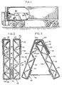
- the bulkhead void filler 20 is used in a cargo bay or area 22 for filling empty spaces or areas in a cargo bay 22 during the shipment of cargo 24 to prevent the cargo 24 from shifting during transport.
- the bulkhead void filler 20 may be used in a variety of shipping means, such as a trailer as shown in Fig. 1, or, for example, a ship or airplane cargo bay.
- the bulkhead void filler 20 of the present invention is of a light-weight construction and is generally comprised of a first rigid panel 26 and a second rigid panel 28 that are non-pivotably, but disengagably, attached to each other by a fastener 30 at the rigid panels upper ends 32, 34.
- the void filler 20 may take on one of many sizes, depending on the use.
- the first and second rigid panels 26, 28 are of substantially equal size and similar construction. When the rigid panels 26, 28 are not attached, as illustrated in Fig. 2, the panels 26, 28 lie in a generally flat, side-by-side configuration which allows for easy storage and shipment.
- the bulkhead void filler 20 generally takes the form of an inverted V.
- the bulkhead void filler 20 is placed between the cargo and the walls of the cargo area or bulkhead, or in between separate pieces of cargo.
- the vertical edges of the void filler 20 abut the cargo 24 and/or wall and resist the forces created by the load of the cargo 24 during transport.
- Multiple bulkhead void fillers 20 may be placed in a side-by-side configuration to fill the empty areas in the cargo bay 22 if necessary.
- Each separate rigid panel 26, 28 takes the form of a sandwich-type construction so as to increase the strength of the bulkhead void filler 20 so the bulkhead void filler 20 will not collapse under the pressure of the cargo 24 during shipping.
- the sandwich-type construction is formed by a first, or inner, face sheet 36 and a second, or outer, face sheet 38 attached to each other by a core 40.
- the construction the rigid panels 26, 28 may take one of many forms.
- the rigid panels 26, 28 are substantially identical in construction except for the differences described herein.
- the core 40 is inserted between the face sheets 36, 38, a first end 42 of the inner face sheet 36 is overlapped and bonded to a second end 44 of the outer face sheet 38 a predetermined distance, and a first end 46 of the outer face sheet 36 is overlapped and bonded to a second end 48 of the inner face sheet 36 a predetermined distance.
- suitable means such as adhesive
- Each core 40 is made of a suitable material, such as an angle member of paper, plastic, composite, or other suitable material, and takes the form of a corrugated or zig-zag configuration in order to reinforce and strengthen the rigid panel 26, 28 so as to prevent the panel 26, 28 from collapsing.
- the core 40 may take one of many forms.
- the core 40 is made of at least one folded sheet 50 having a series of individual panels 52 of approximately equal length. However, it is to be understood that multiple folded sheets may be used.
- the individual panels 52 of the folded sheet 50 are angled at 45° to the face sheets 36,38 with a 90° angle between the individual panels 52.
- the folded sheet 50 is attached to the face sheets 36, 38 at substantially all of the fold lines or ridges 54 by suitable means such as a bonding adhesive.
- the core 40 includes multiple M-shaped braces 41.
- Each brace 41 is made up of two V-shaped sheets 43,45, preferably made of an angle member, laid side-by-side to create the M-shape.
- a connecting V-shaped sheet 47 preferably made of an angle member, overlaps a leg 49,51 of each V-shaped sheet 43,45, respectively, and attaches the two sheets 43,45 together.
- the connecting sheet 47 is bonded to sheets 43,45 by suitable means 53 such as adhesive.
- the legs 49,51 of the sheets 43,45,47 are angled at approximately 45° to the face sheets 36,38 with a 90° angle between the legs 49, 51.
- the M-shaped braces 41 may be spaced depending on the strength needed in the particular application.
- the space 55 can vary from one half of an inch (1cm) up to twenty inches (50cm). This flexibility allows the M-brace 41 to be used in a variety of applications.
- the M-shaped braces 41 are attached to the face sheets 36,38 at substantially all of the fold lines or ridges 57 by suitable means such as a bonding adhesive.
- the novel fastener 30 of the present invention allows the rigid panels 26, 28 to be attached in a non-pivotable configuration, while also allowing the rigid panels 26, 28 to be detached from each other for easier storage as described hereinabove.
- the non-pivotable configuration of the fastener 30 will not allow the bulkhead void filler 20 to collapse or pivot to a closed position under pressure which overcomes a disadvantage presented by prior art pivotable bulk head void fillers.
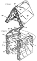
- the inside face sheet 36 of the first panel 26 is cut along a horizontal line 56 at a predetermined distance from the upper end 32 of the first panel 26 in order to form a flap or panel section 58.
- the flap 58 is not attached to the core 40 and is free moving since the upper portion of the inner face sheet 36 is not bonded to the corrugated core 40.
- the flap 58 must be of a sufficient length to securely hold the second rigid panel 28 against the first panel 26 as will be described in detail herein.
- the upper end 34 of the second rigid panel 28 is placed in an abutting relationship with the two uppermost exposed individual panels 52a, 52b of the core 40 of the first rigid panel 26 and attached thereto by suitable attaching means 66.
- the upper-most panel 52a abuts the top 62 of the second rigid panel 28 and the second upper-most panel 52b abuts a portion of the side 64 of the second panel 28.
- the upper end 34 of the second panel 28 fits snugly against the core 40.
- the flap or panel section 58 is folded over the upper end 34 of the second panel 28 and mates with a panel section 59 of the second panel 28.
- the panel sections 58, 59 are attached by suitable attaching means 68, preferably releasable, to complete the fastener 30.
- the rigid panels 26, 28 are at approximately a 45° angle to each other and cannot pivot in relation to each other.
- the panels 26, 28 cannot spread outwardly since the second panel 28 fits snugly against the core 40 which prevents motion in the outward direction.
- the panels 26, 28 cannot move inwardly since the flap 58, when folded over and attached to the second panel 28, prevents motion in the inward direction.
- the flap 58 is attached to the outer face sheet 38 of the second panel 28 by using Velcro patches 70 on the flap 58 with complementary Velcro patches 72 on the outer face sheet 38.
- the top 62 of the second panel 28 is attached to the upper-most individual panel 52a of the core 40 in the first panel 26 by attaching means 66.
- the top 62 of the second panel 28 has Velcro patches 74 and the upper-most individual panel 52a of the core 40 has complementary Velcro patches 76 for attachment thereto.
- Velcro may be used as illustrated in the Figs., or a strip of Velcro may be used. Velcro is advantageous to use since it can be attached and detached multiple times while holding the panels 26, 28 securely together. It is to be understood that other forms of attaching means may be used without departing from the scope of the invention.
- the bulkhead void filler 20 may have a connecting means 78 that also serves the function of a spread-limiter.
- the connecting means or spread-limiter 78 is a sheet attached to the overlapping or first end 46 of the outer face sheet 38 of each of the rigid panels 26, 28 at a small distance above the bottom end 80 of each rigid panel 26, 28.
- the connecting means or spread-limiter 78 is attached to the overlapping portion 46 of the outer face sheets 38 by suitable means, such as adhesive, and is made of a suitable material having high strength, such as Kraft paper.
- the connector means or spread-limiter 78 serves two functions. First, when the rigid panels 26, 28 are in the disassembled condition, as shown in Figs. 2 and 4, the connecting means 78 keeps the panels 26, 28 in matched pairs. In this condition, the connector means 78 is collapsed along a fold line 82 and the rigid panels 26, 28 may be placed in a generally flat, side-by-side configuration, as shown in Fig. 2. This configuration allows for easier shipment and storage of the bulkhead void filler 20 since it can be folded up in a compact manner.
- the spread-limiter 78 defines the maximum distance the bottom ends 80 of the rigid panels 26, 28 may be apart and prevents the rigid panels 26, 28 from spreading any greater distance.
- the bottom ends 80 of the rigid panels 26, 28 are spread apart approximately the length of the spread-limiter 78.
- the rigid panels 26, 28 are only allowed to spread 45'' to 46'' (114 to 117cm) when used with a 92'' or 96'' (233 to 244cm) wide trailer cargo area and in the preferred embodiment, the spread-limiter 78 allows the panels 26, 28 to spread apart a distance of 46'' (117cm) when used with a 92'' or 96'' (233 to 244cm) wide trailer cargo area.
Landscapes
- Engineering & Computer Science (AREA)
- Mechanical Engineering (AREA)
- Transportation (AREA)
- Buffer Packaging (AREA)
- Pallets (AREA)
Applications Claiming Priority (2)
| Application Number | Priority Date | Filing Date | Title |
|---|---|---|---|
| US74587 | 1993-06-11 | ||
| US08/074,587 US5374464A (en) | 1993-06-11 | 1993-06-11 | Bulkhead void filler |
Publications (1)
| Publication Number | Publication Date |
|---|---|
| EP0628449A1 true EP0628449A1 (fr) | 1994-12-14 |
Family
ID=22120385
Family Applications (1)
| Application Number | Title | Priority Date | Filing Date |
|---|---|---|---|
| EP19940304223 Ceased EP0628449A1 (fr) | 1993-06-11 | 1994-06-10 | Entretoise de charge |
Country Status (3)
| Country | Link |
|---|---|
| US (1) | US5374464A (fr) |
| EP (1) | EP0628449A1 (fr) |
| FI (1) | FI942717A7 (fr) |
Cited By (2)
| Publication number | Priority date | Publication date | Assignee | Title |
|---|---|---|---|---|
| EP0661191A1 (fr) * | 1994-01-03 | 1995-07-05 | Shippers Paper Products Co. | Entretoise de charge |
| EP1712492A1 (fr) * | 2005-04-12 | 2006-10-18 | Deere & Company | Cloison pliable pour un conteneur de fret |
Families Citing this family (9)
| Publication number | Priority date | Publication date | Assignee | Title |
|---|---|---|---|---|
| US6431804B1 (en) | 1999-06-30 | 2002-08-13 | Wetzig, Iii John M. | Endgate |
| US7416775B2 (en) * | 2003-07-11 | 2008-08-26 | Unda Maris B.V. | Wall element |
| US20050008826A1 (en) * | 2003-07-11 | 2005-01-13 | Snel Wilhelmus J.R.K. | Wall element at least substantially made of cellulose material |
| JP2009094488A (ja) * | 2007-09-21 | 2009-04-30 | Semiconductor Energy Lab Co Ltd | 半導体膜付き基板の作製方法 |
| US9545775B2 (en) * | 2011-05-02 | 2017-01-17 | Samer U. Al-Azem | Attachment systems and methods usable to form enclosures |
| US9033628B1 (en) * | 2013-03-14 | 2015-05-19 | Hexacomb Corporation | Paper roll transit pad |
| US10518499B2 (en) * | 2016-09-26 | 2019-12-31 | Corruven Canada Inc. | Foldable composite material sheet and structure |
| US11084651B2 (en) * | 2018-08-03 | 2021-08-10 | Baselinx Llc | Temporary bulkhead for shipping container |
| USRE50020E1 (en) * | 2018-08-03 | 2024-06-25 | Baselinx Llc | Temporary bulkhead for shipping container |
Citations (2)
| Publication number | Priority date | Publication date | Assignee | Title |
|---|---|---|---|---|
| US4494897A (en) * | 1983-02-10 | 1985-01-22 | Rogers Eugene A | Damage prevention void filler for separating loads during transit |
| US5132156A (en) * | 1990-03-07 | 1992-07-21 | Down River International, Inc. | Void filler |
Family Cites Families (3)
| Publication number | Priority date | Publication date | Assignee | Title |
|---|---|---|---|---|
| GB581381A (en) * | 1944-03-15 | 1946-10-10 | Arthur Kremer | Improvements in or relating to sheet material having an outer covering or skin |
| US4390578A (en) * | 1980-03-13 | 1983-06-28 | Blacknell Buildings Limited | Method of joining members |
| US4880679A (en) * | 1988-03-25 | 1989-11-14 | Phillips Petroleum Company | EMI Shielded plastic composites |
-
1993
- 1993-06-11 US US08/074,587 patent/US5374464A/en not_active Expired - Lifetime
-
1994
- 1994-06-09 FI FI942717A patent/FI942717A7/fi not_active Application Discontinuation
- 1994-06-10 EP EP19940304223 patent/EP0628449A1/fr not_active Ceased
Patent Citations (3)
| Publication number | Priority date | Publication date | Assignee | Title |
|---|---|---|---|---|
| US4494897A (en) * | 1983-02-10 | 1985-01-22 | Rogers Eugene A | Damage prevention void filler for separating loads during transit |
| US4494897B1 (en) * | 1983-02-10 | 1993-03-23 | Damage prevention void filler for separating loads during transit | |
| US5132156A (en) * | 1990-03-07 | 1992-07-21 | Down River International, Inc. | Void filler |
Cited By (3)
| Publication number | Priority date | Publication date | Assignee | Title |
|---|---|---|---|---|
| EP0661191A1 (fr) * | 1994-01-03 | 1995-07-05 | Shippers Paper Products Co. | Entretoise de charge |
| EP1712492A1 (fr) * | 2005-04-12 | 2006-10-18 | Deere & Company | Cloison pliable pour un conteneur de fret |
| US7357611B2 (en) | 2005-04-12 | 2008-04-15 | Deere & Company | Foldable shipping container bulkhead |
Also Published As
| Publication number | Publication date |
|---|---|
| FI942717A0 (fi) | 1994-06-09 |
| US5374464A (en) | 1994-12-20 |
| FI942717A7 (fi) | 1994-12-12 |
Similar Documents
| Publication | Publication Date | Title |
|---|---|---|
| US6050410A (en) | Foldable pallet-mounted container | |
| US4970743A (en) | Mattress and foundation system useable with water mattresses | |
| US6041718A (en) | Corrugated collapsible container pack | |
| US2778560A (en) | Collapsible box | |
| US3371815A (en) | Freight binding device | |
| US5016813A (en) | Fold-up container and construction method | |
| US5685644A (en) | Bulk cargo bag | |
| US3949929A (en) | Collapsible container construction having hook and pile interconnecting means | |
| EP0628449A1 (fr) | Entretoise de charge | |
| BRPI0617078A2 (pt) | recipiente octogonal para granel | |
| CA2253122A1 (fr) | Boite de transport en vrac a montage rapide | |
| US4546941A (en) | Foldable support structure of cardboard, plastic and the like | |
| US6241148B1 (en) | Polygon-shaped container | |
| US20020008517A1 (en) | Octagon shaped flexible intermediate bulk container and method of manufacture | |
| US5390790A (en) | Octagonal container with smooth inner bottom surface | |
| EP0487156B1 (fr) | Récipient pour produits en vrac, fluides et analogues | |
| US5484241A (en) | Collapsible void filler | |
| US5409755A (en) | Bulkhead void filler | |
| US5517926A (en) | Collapsible pallet | |
| US5775571A (en) | Automatic pop up, bulk bin, multi-sided container apparatus | |
| US5413824A (en) | Collapsible and expandable roll riser | |
| EP2214974B1 (fr) | Recipients, en particulier pour des produits agricoles | |
| US5378096A (en) | Collapsible and expandable void filler | |
| JPH0755710B2 (ja) | 段ボール製パレット | |
| JPH0755711B2 (ja) | 段ボール製パレット |
Legal Events
| Date | Code | Title | Description |
|---|---|---|---|
| PUAI | Public reference made under article 153(3) epc to a published international application that has entered the european phase |
Free format text: ORIGINAL CODE: 0009012 |
|
| AK | Designated contracting states |
Kind code of ref document: A1 Designated state(s): AT BE CH DE DK ES FR GB GR IT LI NL SE |
|
| 17P | Request for examination filed |
Effective date: 19950426 |
|
| GRAG | Despatch of communication of intention to grant |
Free format text: ORIGINAL CODE: EPIDOS AGRA |
|
| 17Q | First examination report despatched |
Effective date: 19960814 |
|
| STAA | Information on the status of an ep patent application or granted ep patent |
Free format text: STATUS: THE APPLICATION HAS BEEN REFUSED |
|
| 18R | Application refused |
Effective date: 19970202 |