EP0628459A1 - Sicherheits-Druckreserve sowie hierfür geeigneter Speicher für Kraftfahrzeug-Hinterradbremse - Google Patents
Sicherheits-Druckreserve sowie hierfür geeigneter Speicher für Kraftfahrzeug-Hinterradbremse Download PDFInfo
- Publication number
- EP0628459A1 EP0628459A1 EP94401092A EP94401092A EP0628459A1 EP 0628459 A1 EP0628459 A1 EP 0628459A1 EP 94401092 A EP94401092 A EP 94401092A EP 94401092 A EP94401092 A EP 94401092A EP 0628459 A1 EP0628459 A1 EP 0628459A1
- Authority
- EP
- European Patent Office
- Prior art keywords
- reserve
- piston
- pressure
- chamber
- elastic means
- Prior art date
- Legal status (The legal status is an assumption and is not a legal conclusion. Google has not performed a legal analysis and makes no representation as to the accuracy of the status listed.)
- Granted
Links
- 239000000725 suspension Substances 0.000 claims description 29
- 239000007788 liquid Substances 0.000 claims description 4
- 238000005461 lubrication Methods 0.000 claims description 4
- 238000007665 sagging Methods 0.000 description 5
- IJGRMHOSHXDMSA-UHFFFAOYSA-N Atomic nitrogen Chemical compound N#N IJGRMHOSHXDMSA-UHFFFAOYSA-N 0.000 description 4
- 229920001971 elastomer Polymers 0.000 description 2
- 239000000806 elastomer Substances 0.000 description 2
- 229910052757 nitrogen Inorganic materials 0.000 description 2
- 229910001209 Low-carbon steel Inorganic materials 0.000 description 1
- 239000000428 dust Substances 0.000 description 1
- 239000012530 fluid Substances 0.000 description 1
- 239000007789 gas Substances 0.000 description 1
- 230000001050 lubricating effect Effects 0.000 description 1
- 239000002184 metal Substances 0.000 description 1
- 239000004033 plastic Substances 0.000 description 1
- 239000004810 polytetrafluoroethylene Substances 0.000 description 1
- 229920001343 polytetrafluoroethylene Polymers 0.000 description 1
- 238000011144 upstream manufacturing Methods 0.000 description 1
- XLYOFNOQVPJJNP-UHFFFAOYSA-N water Substances O XLYOFNOQVPJJNP-UHFFFAOYSA-N 0.000 description 1
Images

Classifications
-
- B—PERFORMING OPERATIONS; TRANSPORTING
- B60—VEHICLES IN GENERAL
- B60G—VEHICLE SUSPENSION ARRANGEMENTS
- B60G17/00—Resilient suspensions having means for adjusting the spring or vibration-damper characteristics, for regulating the distance between a supporting surface and a sprung part of vehicle or for locking suspension during use to meet varying vehicular or surface conditions, e.g. due to speed or load
- B60G17/02—Spring characteristics, e.g. mechanical springs and mechanical adjusting means
- B60G17/04—Spring characteristics, e.g. mechanical springs and mechanical adjusting means fluid spring characteristics
- B60G17/0408—Spring characteristics, e.g. mechanical springs and mechanical adjusting means fluid spring characteristics details, e.g. antifreeze for suspension fluid, pumps, retarding means per se
-
- B—PERFORMING OPERATIONS; TRANSPORTING
- B60—VEHICLES IN GENERAL
- B60T—VEHICLE BRAKE CONTROL SYSTEMS OR PARTS THEREOF; BRAKE CONTROL SYSTEMS OR PARTS THEREOF, IN GENERAL; ARRANGEMENT OF BRAKING ELEMENTS ON VEHICLES IN GENERAL; PORTABLE DEVICES FOR PREVENTING UNWANTED MOVEMENT OF VEHICLES; VEHICLE MODIFICATIONS TO FACILITATE COOLING OF BRAKES
- B60T13/00—Transmitting braking action from initiating means to ultimate brake actuator with power assistance or drive; Brake systems incorporating such transmitting means, e.g. air-pressure brake systems
- B60T13/10—Transmitting braking action from initiating means to ultimate brake actuator with power assistance or drive; Brake systems incorporating such transmitting means, e.g. air-pressure brake systems with fluid assistance, drive, or release
- B60T13/12—Transmitting braking action from initiating means to ultimate brake actuator with power assistance or drive; Brake systems incorporating such transmitting means, e.g. air-pressure brake systems with fluid assistance, drive, or release the fluid being liquid
- B60T13/14—Transmitting braking action from initiating means to ultimate brake actuator with power assistance or drive; Brake systems incorporating such transmitting means, e.g. air-pressure brake systems with fluid assistance, drive, or release the fluid being liquid using accumulators or reservoirs fed by pumps
- B60T13/148—Arrangements for pressure supply
Definitions
- the present invention relates to a safety pressure reserve for a rear brake of a motor vehicle, as well as a pressure accumulator for producing the aforementioned reserve.
- Motor vehicle safety regulations require that motor vehicles fitted with hydropneumatic suspensions and high pressure braking systems be fitted with a safety pressure reserve integrated into the suspension circuit and put into service in the event of a failure of the hydraulic circuit, so as to stop the vehicle either by means of the front or rear braking systems for the I-circuits, or diagonally for the X-circuits.
- a safety valve isolates the front and rear circuits, in the event of failure, from a pre-established pressure threshold, so as to set in use the front brakes via the main accumulator, if the failure occurs at the rear of the vehicle, or else activate the rear brakes via the suspension spheres if the failure occurs at the rear 'before.
- suspension spheres as a brake reserve can cause a sudden collapse of the rear suspension each time the vehicle is restarted, by transferring the liquid from the rear suspension spheres to the brake reserve.
- the hydraulic circuit comprises two anti-sagging valves controlled by the high pressure circuit and interposed respectively between the safety valve and the front cylinders for one, and the safety valve and the rear cylinders for the second
- the safety valve isolates the fault but the valves also close. If the fault occurs at the rear, the main accumulator ensures braking at the front. If the failure occurs at the front, the closing of the anti-sagging valves occurring substantially at the same time as the closing of the safety valve, prevents communication with the spheres, whereby the rear braking can no longer be assured. It is then necessary to provide an auxiliary safety pressure reserve in the rear brake circuit.
- the present invention solves these problems and proposes a safety pressure reserve for a rear brake of a motor vehicle, as well as an accumulator for its realization, of simple design, independent of the dynamic pressures of the rear suspension.
- the subject of the present invention is a safety pressure reserve, in particular for the rear brake of a motor vehicle equipped with a hydropneumatic suspension in which the suspension liquid controls the brakes, this reserve being characterized in that it comprises a pressure accumulator comprising a body of substantially cylindrical shape, in which a piston is mounted movable in translation by dividing said body into a first chamber communicating with the braking circuit and a second chamber in which are provided elastic means urging the piston towards the first chamber.
- the second chamber has an annular part surrounding said body.
- the elastic means are mechanical means.
- these elastic means comprise a spring or the like acting on the piston.
- the accumulator comprises a bell-shaped part comprising, at its base, a collar on which the aforementioned spring is in abutment and fixed by its upper part to a rod acting on the aforementioned piston.
- the aforementioned second bedroom communicates with a protected enclosure.
- the elastic means are pneumatic means.
- the aforementioned pneumatic means comprise a mass of pressurized gas enclosed in the second chamber.
- means for lubricating the piston are provided in the reserve.
- these lubrication means comprise a reserve of oil limited by two chamfers provided respectively on the body and the piston.
- the elastic means are predetermined so that the residual pressure in the braking circuit is greater than or equal to a given value when the piston is in the expansion stop.
- the elastic means are predetermined so that the piston is in abutment attack for a pressure in the circuit lower than the suspension pressure when the vehicle is running.
- the invention also relates to a pressure accumulator for producing a safety pressure reserve comprising one or more of the previously mentioned characteristics taken alone or in combination.
- Figure 1 is a schematic illustration of the hydropneumatic suspension circuit of a motor vehicle.
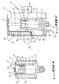
- FIG. 2 illustrates a first embodiment of a pressure accumulator according to the invention.
- FIG. 3 illustrates a second embodiment of a pressure accumulator according to the invention.
- a hydropneumatic suspension and braking circuit comprising a high pressure pump 14 connected upstream to a reservoir 15 containing the hydraulic fluid and downstream to a contactor-circuit breaker 16 on which a so-called main accumulator is mounted 17.
- the contactor-circuit breaker 16 is intended to maintain a constant pressure in the main accumulator 17, which supplies the various hydraulically operating elements of the vehicle, namely the suspension system, the braking system, the steering etc ...
- the main accumulator 17 is connected downstream to a safety valve 18, itself connected to a brake metering device 19 controlled by the brake pedal 20 and which determines, as a function of the force exerted on the pedal 20, the pressure in the front brake circuit 21.
- the safety valve 18 has a bore 22 in which slides a drawer 23 on which pressure is exerted from the main accumulator 17, and on the other hand that of an opposing spring 24.
- This slide 23 is movable in front of the two orifices 23a and 23b of the pipes leading respectively to the two height correctors 25 and 26 and on the other hand to the two anti-sagging valves 27, 28.
- the front anti-sagging valve 28 is connected to the support elements 29, 30 (or suspension cylinders) on which the spheres 31 and 32 are mounted.
- the anti-sag rear subsidence 27 is connected on the one hand, to the suspension cylinders 33, 34 comprising respectively the suspension spheres 35 and 36, and on the other hand, to the metering device 19 which determines the pressure in the rear brake circuit 37 by l 'inter medium of a pipe 38 and a safety reserve in accordance with the invention R.
- this reserve R comprises a body 1 in which slides a piston 2 surrounded by two guide segments made of PTFE 39, 40 and an elastomer seal 41.
- An envelope 42 comprising two fixing lugs 43, 44 is crimped onto the body 1, which has a groove 45 at this location allowing the two parts to be anchored.
- a spring 6 is supported by one of its ends on the bottom of the envelope 42 while being centered in the latter at 46, and by its opposite end on a bell-shaped element 7 while being centered on this- ci in 47.
- the bell 7 is connected to the piston 2 by means of a shouldered screw 9 blocked on the piston 2 and crimped at the other end on the bell 7.
- the body 1 has a nozzle 49 glued which will allow, via a plastic tube (not shown) fitted on it and opening at the other end in a hollow body containing neither water nor dust, the variations in volume of the enclosure 50 generated by the piston 2 travel.
- this reserve comprises a body 1 in which slides a piston 2 surrounded by two guide segments 39,40, and an elastomer seal 41.
- a envelope 42 is welded to body 1 either by laser or any other type of weld at 51.
- This reserve R is inflated by pressurized nitrogen which is injected through opening 53 which is then closed with sealingly by means of a mild steel ball 54 electrically welded to the opening 53 and which takes the form of a wafer.
- an oil wedge 11 is provided, produced by means of a chamfer 12 on the body 1 and another chamfer 13 on the piston 2, in order to provide lubrication of the piston 2 in the body 1.
- this reserve R is less bulky and lighter than the metal spring reserve previously described.
- the front brakes 21 are permanently supplied with pressure by the main accumulator 17, and the rear brakes 37 by the rear suspension accumulators 35 and 36.
- the safety valve 18 separates the accumulator main 17 of the suspension accumulators 35 and 36 for a pressure threshold predetermined by the spring 24, so that when an incident causing a significant leak occurs, either at the front or at the rear, the braking is always insured on the side opposite the side of the incident.
- a sag valve is mounted on each axle of a vehicle, as illustrated in 27, 28, and a significant leak occurs at the front of the vehicle, the valve 18 closes, same time as the two anti-sagging valves 27, 28, since they are controlled by the pressure of the main accumulator 17.
- the pressure reserve R is put into operation by to provide some pressure in the rear brakes.
- the spring pressure and the amount of nitrogen will be adjusted so that when the piston is in the expansion stop, that is to say at the end of the stroke after safety operation, the pressure in the circuit for example is at least 38 bar, and that when it is in the attack position, position illustrated in the figures, it is at a pressure less than or equal to the suspension pressure back when the vehicle is running, to prevent the piston from operating in normal vehicle use.
- the main advantages of the invention lie in that the brake reserve is independent of the dynamic pressures of the rear suspension, and therefore does not participate in the suspension as is the case for the suspension spheres.
- the rear suspension is advantageously prevented from collapsing suddenly each time the vehicle is restarted by transferring the liquid from the rear suspension spheres to the brake reserve, the piston being pushed back before the suspension pressure is reached.
Landscapes
- Engineering & Computer Science (AREA)
- Mechanical Engineering (AREA)
- Transportation (AREA)
- Vehicle Body Suspensions (AREA)
Applications Claiming Priority (2)
| Application Number | Priority Date | Filing Date | Title |
|---|---|---|---|
| FR9306783 | 1993-06-07 | ||
| FR9306783A FR2706148B1 (fr) | 1993-06-07 | 1993-06-07 | Réserve de pression de sécurité pour frein arrière de véhicule automobile et accumulateur de pression pour la réalisation de la réserve précitée. |
Publications (2)
| Publication Number | Publication Date |
|---|---|
| EP0628459A1 true EP0628459A1 (de) | 1994-12-14 |
| EP0628459B1 EP0628459B1 (de) | 1999-01-13 |
Family
ID=9447819
Family Applications (1)
| Application Number | Title | Priority Date | Filing Date |
|---|---|---|---|
| EP19940401092 Expired - Lifetime EP0628459B1 (de) | 1993-06-07 | 1994-05-17 | Hydraulikkreis mit Sicherheits-Druckreserve für Kraftfahrzeug-Hinterradbremse sowie damit ausgerüstetes Kraftfahrzeug |
Country Status (3)
| Country | Link |
|---|---|
| EP (1) | EP0628459B1 (de) |
| DE (1) | DE69415870T2 (de) |
| FR (1) | FR2706148B1 (de) |
Cited By (2)
| Publication number | Priority date | Publication date | Assignee | Title |
|---|---|---|---|---|
| EP0950622A3 (de) * | 1998-04-16 | 2000-05-10 | Agristrade S.p.A. | Silo zum Lagern und nachfolgenden dosierten Abgaben in ein oder mehrere Transportfahrzeuge für körniges Material |
| EP1029761A1 (de) * | 1999-02-18 | 2000-08-23 | Peugeot Citroen Automobiles SA | Bremsanlage für Kraftfahrzeuge mit hydropneumatischer Radaufhängung |
Citations (3)
| Publication number | Priority date | Publication date | Assignee | Title |
|---|---|---|---|---|
| FR2328597A1 (fr) * | 1975-10-23 | 1977-05-20 | Citroen Sa | Installation de freinage pour vehicule a suspension oleopneumatique |
| FR2391098A1 (fr) * | 1977-05-17 | 1978-12-15 | Girling Ltd | Perfectionnements aux installations hydrauliques d'assistance de freinage et d'equilibrage de vehicules |
| EP0363827A2 (de) * | 1988-10-05 | 1990-04-18 | Knorr-Bremse Ag | Drehgestellfahrzeug mit elektrohydraulischer Bremse und hydropneumatischer Abfederung |
-
1993
- 1993-06-07 FR FR9306783A patent/FR2706148B1/fr not_active Expired - Fee Related
-
1994
- 1994-05-17 DE DE1994615870 patent/DE69415870T2/de not_active Expired - Fee Related
- 1994-05-17 EP EP19940401092 patent/EP0628459B1/de not_active Expired - Lifetime
Patent Citations (3)
| Publication number | Priority date | Publication date | Assignee | Title |
|---|---|---|---|---|
| FR2328597A1 (fr) * | 1975-10-23 | 1977-05-20 | Citroen Sa | Installation de freinage pour vehicule a suspension oleopneumatique |
| FR2391098A1 (fr) * | 1977-05-17 | 1978-12-15 | Girling Ltd | Perfectionnements aux installations hydrauliques d'assistance de freinage et d'equilibrage de vehicules |
| EP0363827A2 (de) * | 1988-10-05 | 1990-04-18 | Knorr-Bremse Ag | Drehgestellfahrzeug mit elektrohydraulischer Bremse und hydropneumatischer Abfederung |
Cited By (3)
| Publication number | Priority date | Publication date | Assignee | Title |
|---|---|---|---|---|
| EP0950622A3 (de) * | 1998-04-16 | 2000-05-10 | Agristrade S.p.A. | Silo zum Lagern und nachfolgenden dosierten Abgaben in ein oder mehrere Transportfahrzeuge für körniges Material |
| EP1029761A1 (de) * | 1999-02-18 | 2000-08-23 | Peugeot Citroen Automobiles SA | Bremsanlage für Kraftfahrzeuge mit hydropneumatischer Radaufhängung |
| FR2789957A1 (fr) * | 1999-02-18 | 2000-08-25 | Peugeot Citroen Automobiles Sa | Systeme de freinage pour vehicule automobile a suspension hydropneumatique |
Also Published As
| Publication number | Publication date |
|---|---|
| EP0628459B1 (de) | 1999-01-13 |
| DE69415870T2 (de) | 1999-12-02 |
| FR2706148A1 (fr) | 1994-12-16 |
| FR2706148B1 (fr) | 1995-09-08 |
| DE69415870D1 (de) | 1999-02-25 |
Similar Documents
| Publication | Publication Date | Title |
|---|---|---|
| FR2624462A1 (fr) | Systeme de freinage antiblocage pour vehicule automobile | |
| FR2573711A1 (fr) | Systeme hydraulique de freinage avec regulation du glissement | |
| EP0156666B1 (de) | Bremskraftregler | |
| FR2946720A1 (fr) | Amortisseur et atterrisseur equipe d'un tel amortisseur. | |
| FR2656049A1 (fr) | Accumulateur de pression a piston, notamment pour systeme de freinage a regulation du glissement de traction. | |
| FR2917803A1 (fr) | Systeme de clapet d'etancheite | |
| EP0065451A1 (de) | Bremsdruckmodulator für Blockierschutzsysteme | |
| FR2565914A1 (fr) | Dispositif de freins a assistance hydraulique | |
| FR2481215A1 (fr) | Soupape de purge pour un maitre-cylindre a action rapide | |
| EP0005675B1 (de) | Radzylinder | |
| EP0628459B1 (de) | Hydraulikkreis mit Sicherheits-Druckreserve für Kraftfahrzeug-Hinterradbremse sowie damit ausgerüstetes Kraftfahrzeug | |
| EP0161131B1 (de) | Sicherheitsvorrichtung für einen Bremskraftregler | |
| FR2787764A1 (fr) | Dispositif de suspension d'une charge utile dans un lanceur spatial | |
| FR2515592A1 (fr) | Installation de freinage pour remorques de vehicules automobiles | |
| EP0213020B1 (de) | Hydropneumatische Federung für Kraftfahrzeuge mit einem Gegendurchhangungsventil | |
| EP0041020B1 (de) | Druckdosiereinheit für eine Bedienungseinrichtung für Fahrzeugbremsen | |
| EP0091348B1 (de) | Reglerventil für gleichzeitige Speisung hydraulischer Anlagen mit offener und geschlossener Mitte | |
| EP0385816B1 (de) | Druckfluidspeicher | |
| FR2465108A2 (fr) | Dispositif a soupape pour la distribution de fluide sous pression | |
| FR2485459A1 (fr) | Dispositif de freinage pneumatique pour les vehicules automobiles | |
| FR2646225A1 (fr) | Dispositif de lubrification des paliers d'un turbo-compresseur | |
| FR2598132A1 (fr) | Unite de regulation de pression, notamment pour systeme de freinage pour vehicule automobile, a double circuit et commande par un liquide de pression. | |
| FR2652551A1 (fr) | Circuit hydraulique de freinage muni d'un dispositif d'antiblocage des roues pour vehicule automobile. | |
| FR2816032A1 (fr) | Dispositif de limitation du remplissage d'un reservoir de fluide tel le gpl | |
| FR3050495A1 (fr) | Systeme de suspension hydraulique d’un vehicule |
Legal Events
| Date | Code | Title | Description |
|---|---|---|---|
| PUAI | Public reference made under article 153(3) epc to a published international application that has entered the european phase |
Free format text: ORIGINAL CODE: 0009012 |
|
| AK | Designated contracting states |
Kind code of ref document: A1 Designated state(s): DE GB IT |
|
| 17P | Request for examination filed |
Effective date: 19950415 |
|
| 17Q | First examination report despatched |
Effective date: 19960802 |
|
| GRAG | Despatch of communication of intention to grant |
Free format text: ORIGINAL CODE: EPIDOS AGRA |
|
| GRAG | Despatch of communication of intention to grant |
Free format text: ORIGINAL CODE: EPIDOS AGRA |
|
| GRAH | Despatch of communication of intention to grant a patent |
Free format text: ORIGINAL CODE: EPIDOS IGRA |
|
| GRAH | Despatch of communication of intention to grant a patent |
Free format text: ORIGINAL CODE: EPIDOS IGRA |
|
| GRAA | (expected) grant |
Free format text: ORIGINAL CODE: 0009210 |
|
| AK | Designated contracting states |
Kind code of ref document: B1 Designated state(s): DE GB IT |
|
| REF | Corresponds to: |
Ref document number: 69415870 Country of ref document: DE Date of ref document: 19990225 |
|
| ITF | It: translation for a ep patent filed | ||
| GBT | Gb: translation of ep patent filed (gb section 77(6)(a)/1977) |
Effective date: 19990415 |
|
| PLBE | No opposition filed within time limit |
Free format text: ORIGINAL CODE: 0009261 |
|
| STAA | Information on the status of an ep patent application or granted ep patent |
Free format text: STATUS: NO OPPOSITION FILED WITHIN TIME LIMIT |
|
| 26N | No opposition filed | ||
| REG | Reference to a national code |
Ref country code: GB Ref legal event code: IF02 |
|
| PGFP | Annual fee paid to national office [announced via postgrant information from national office to epo] |
Ref country code: GB Payment date: 20030514 Year of fee payment: 10 |
|
| PGFP | Annual fee paid to national office [announced via postgrant information from national office to epo] |
Ref country code: DE Payment date: 20030529 Year of fee payment: 10 |
|
| PG25 | Lapsed in a contracting state [announced via postgrant information from national office to epo] |
Ref country code: GB Free format text: LAPSE BECAUSE OF NON-PAYMENT OF DUE FEES Effective date: 20040517 |
|
| PG25 | Lapsed in a contracting state [announced via postgrant information from national office to epo] |
Ref country code: DE Free format text: LAPSE BECAUSE OF NON-PAYMENT OF DUE FEES Effective date: 20041201 |
|
| GBPC | Gb: european patent ceased through non-payment of renewal fee |
Effective date: 20040517 |
|
| PG25 | Lapsed in a contracting state [announced via postgrant information from national office to epo] |
Ref country code: IT Free format text: LAPSE BECAUSE OF NON-PAYMENT OF DUE FEES Effective date: 20050517 |