EP0628516A1 - Verfahren und Vorrichtung zum katalytischen Entfernen von Sauerstoff aus Wasser - Google Patents
Verfahren und Vorrichtung zum katalytischen Entfernen von Sauerstoff aus Wasser Download PDFInfo
- Publication number
- EP0628516A1 EP0628516A1 EP94106743A EP94106743A EP0628516A1 EP 0628516 A1 EP0628516 A1 EP 0628516A1 EP 94106743 A EP94106743 A EP 94106743A EP 94106743 A EP94106743 A EP 94106743A EP 0628516 A1 EP0628516 A1 EP 0628516A1
- Authority
- EP
- European Patent Office
- Prior art keywords
- water
- hydrogen
- oxygen
- bed
- catalyst bed
- Prior art date
- Legal status (The legal status is an assumption and is not a legal conclusion. Google has not performed a legal analysis and makes no representation as to the accuracy of the status listed.)
- Granted
Links
- XLYOFNOQVPJJNP-UHFFFAOYSA-N water Substances O XLYOFNOQVPJJNP-UHFFFAOYSA-N 0.000 title claims abstract description 47
- QVGXLLKOCUKJST-UHFFFAOYSA-N atomic oxygen Chemical compound [O] QVGXLLKOCUKJST-UHFFFAOYSA-N 0.000 title claims abstract description 16
- 239000001301 oxygen Substances 0.000 title claims abstract description 16
- 229910052760 oxygen Inorganic materials 0.000 title claims abstract description 16
- 230000003197 catalytic effect Effects 0.000 title claims abstract description 12
- 238000000034 method Methods 0.000 title claims description 16
- 230000008030 elimination Effects 0.000 title description 2
- 238000003379 elimination reaction Methods 0.000 title description 2
- 238000009434 installation Methods 0.000 title 1
- 239000001257 hydrogen Substances 0.000 claims abstract description 43
- 229910052739 hydrogen Inorganic materials 0.000 claims abstract description 43
- UFHFLCQGNIYNRP-UHFFFAOYSA-N Hydrogen Chemical compound [H][H] UFHFLCQGNIYNRP-UHFFFAOYSA-N 0.000 claims abstract description 41
- 239000003054 catalyst Substances 0.000 claims abstract description 38
- 239000008213 purified water Substances 0.000 claims description 4
- KDLHZDBZIXYQEI-UHFFFAOYSA-N Palladium Chemical compound [Pd] KDLHZDBZIXYQEI-UHFFFAOYSA-N 0.000 description 6
- 238000006243 chemical reaction Methods 0.000 description 5
- 239000002245 particle Substances 0.000 description 5
- 239000000243 solution Substances 0.000 description 5
- 230000000694 effects Effects 0.000 description 3
- 150000002431 hydrogen Chemical class 0.000 description 3
- 229910052763 palladium Inorganic materials 0.000 description 3
- 230000035484 reaction time Effects 0.000 description 3
- MYRTYDVEIRVNKP-UHFFFAOYSA-N 1,2-Divinylbenzene Chemical compound C=CC1=CC=CC=C1C=C MYRTYDVEIRVNKP-UHFFFAOYSA-N 0.000 description 2
- 239000004793 Polystyrene Substances 0.000 description 2
- 239000007795 chemical reaction product Substances 0.000 description 2
- 239000000463 material Substances 0.000 description 2
- 229920002223 polystyrene Polymers 0.000 description 2
- 230000003068 static effect Effects 0.000 description 2
- 238000009423 ventilation Methods 0.000 description 2
- 238000009825 accumulation Methods 0.000 description 1
- 150000001450 anions Chemical class 0.000 description 1
- 238000011001 backwashing Methods 0.000 description 1
- 238000006555 catalytic reaction Methods 0.000 description 1
- 239000003153 chemical reaction reagent Substances 0.000 description 1
- 239000011248 coating agent Substances 0.000 description 1
- 238000000576 coating method Methods 0.000 description 1
- 230000006866 deterioration Effects 0.000 description 1
- 238000010438 heat treatment Methods 0.000 description 1
- 238000002347 injection Methods 0.000 description 1
- 239000007924 injection Substances 0.000 description 1
- 238000012423 maintenance Methods 0.000 description 1
- 238000004519 manufacturing process Methods 0.000 description 1
- 238000004377 microelectronic Methods 0.000 description 1
- 239000000203 mixture Substances 0.000 description 1
- 230000004048 modification Effects 0.000 description 1
- 238000012986 modification Methods 0.000 description 1
- 239000000376 reactant Substances 0.000 description 1
- 239000011347 resin Substances 0.000 description 1
- 229920005989 resin Polymers 0.000 description 1
- 150000003839 salts Chemical class 0.000 description 1
- 239000007787 solid Substances 0.000 description 1
- 238000001179 sorption measurement Methods 0.000 description 1
- 238000012619 stoichiometric conversion Methods 0.000 description 1
- 239000000126 substance Substances 0.000 description 1
- 238000011144 upstream manufacturing Methods 0.000 description 1
- 238000009849 vacuum degassing Methods 0.000 description 1
Images
Classifications
-
- C—CHEMISTRY; METALLURGY
- C02—TREATMENT OF WATER, WASTE WATER, SEWAGE, OR SLUDGE
- C02F—TREATMENT OF WATER, WASTE WATER, SEWAGE, OR SLUDGE
- C02F1/00—Treatment of water, waste water, or sewage
- C02F1/70—Treatment of water, waste water, or sewage by reduction
Definitions
- the invention relates to a method and a device for the catalytic removal of oxygen from water, wherein hydrogen is introduced into the water and this is then passed through a catalyst bed.
- Water with a low residual oxygen content is required, for example, as feed water for steam generators, for heating circuits, in microelectronics, as process water in the chemical industry and as injection water for offshore oil production.
- catalytic oxygen removal represents a further development insofar as it is possible to work with little space and reduced operating costs. Maintenance is also low, since feed pumps are the only moving parts of the system.
- the resulting reaction product consists exclusively of water and is therefore environmentally friendly. The efficiency of the process is almost constant over a wide temperature range. The process is not affected by any salt content in the water to be cleaned.
- the hydrogen as a reactant can only be effective if it accumulates on the surface of the particles of the catalyst bed.
- These particles are preferably palladium-doped anion exchangers based on divinylbenzene and polystyrene.
- An addition or reaction presupposes that the hydrogen is dissolved in the water to be degassed.
- the water is usually passed through a hydrogen distributor and then through an external static mixer before it is allowed to flow from top to bottom through the fixed bed catalyst bed.
- the invention is based, the effectiveness of the task To increase catalytic oxygen removal, especially in terms of efficiency and response time.
- the method according to the invention is characterized in that the water is passed from bottom to top through the catalyst bed, the latter being operated in countercurrent as a floating bed.
- the catalyst bed also works as a mixer and is optimally effective. After the water has passed through a nozzle bottom located below the catalyst bed, the hydrogen solution is not yet complete. Rather, the dissolving process is completed when flowing through the catalyst bed. Since the catalyst bed is in the floating bed state, approx. 20-25% of the palladium resin is in the floating state, while approx. 80-75% are located as a fixed bed on an upper nozzle floor. The countercurrent flow through this catalyst bed results in an intensive accumulation of hydrogen on the surface of the catalyst particles. Hydrogen bubbles that could impair the catalytic effect are almost excluded. There is also no longer any danger that - as in the direct current process - a hydrogen bubble forms above the catalyst bed, which must be vented, the hydrogen being lost for the desired reaction.
- the catalyst bed is an enlarged mixing system and shortens the start-up and shutdown times as well as the required reaction time.
- the hydrogen consumption is reduced practically without excess to the stoichiometrically required level.
- the process therefore works with very good efficiency, with a residual oxygen content of ⁇ 10ppb being readily achievable.
- the pressure of the hydrogen is preferably set higher than that of the water.
- This pressure difference has the effect that hydrogen which has not entered solution is forced through the floating bed layer above the bottom of the nozzle and then through the fixed bed layer located at the top of the nozzle.
- This ensures that the catalysis is always effective when passing through the fixed bed.
- This contributes to reducing the excess hydrogen compared to the known direct current method.
- the latter leads to a pressure build-up of the hydrogen which has not gone into solution above the catalyst bed.
- This pressure build-up requires a safety device for pressure relief with a relief line leading to the atmosphere. A significant deterioration in the desired stoichiometric conversion of hydrogen is therefore the result of the direct current process. With the counterflow method, however, the relief line can be omitted in most operating applications.
- the invention also provides a device for the catalytic removal of oxygen from water, comprising a container, a first nozzle plate arranged in the container, and a device arranged in the container above the first nozzle plate Catalyst bed, a supply device connected to the container for oxygen-laden water and hydrogen and with an outlet line connected to the container for purified water.
- This device is characterized in that the feed device is connected below the first nozzle bottom and the outlet line above the catalyst bed to the container, the container advantageously having a second nozzle bottom below the outlet line and above the catalyst bed, so that the floating bed accumulates here and in upper area can reach the density of a fixed bed.
- This device allows the catalyst bed to be operated in countercurrent as a floating bed. This results in a very good efficiency of the catalytic oxygen removal, whereby it is possible to work with very short reaction times.
- the first or lower nozzle floor works as a mixing and water distribution stage for the subsequent floating bed layer. This fulfills the function of a first reaction zone and a loose mixture layer.
- This is followed by the fixed bed layer located on the second or upper nozzle base, which forms a second reaction zone and solid mixing layer. Supported by the pressure difference between the hydrogen and the water, the hydrogen bubbles that have not gone into solution rise, forcing them to be forced through the fixed bed layer.
- the fixed bed layer ensures that the hydrogen bubbles are in constant reaction contact with the individual particles of the catalyst bed in the course of the pressure equalization.
- the supply device for the oxygen-laden water and the hydrogen can consist of two separate lines which open at the bottom of the container. On the other hand, it is more advantageous to provide an inlet line for the oxygen-laden water, in which a hydrogen line opens. Water and reagent thus enter the container together and flow to the floating bed in a reasonably evenly distributed manner.
- the invention is explained in more detail below on the basis of a preferred exemplary embodiment of a device according to the invention.
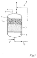
- the figure shows a schematic representation of the device.
- the device comprises a container 1, in which a first nozzle base 2 is arranged.
- a catalyst bed 3 is located above the bottom of the nozzle.
- the catalyst bed 3 When the device is out of operation, the catalyst bed 3 rests on the nozzle base 2. In the operating state shown, the catalyst bed 3 acts as a floating bed through which flow flows from bottom to top. It is sponged, laying against a second nozzle base 4, with an increasing density. It forms a lower floating bed layer, which contains approx. 20-25% of the catalyst material, and an upper fixed bed layer, which contains the rest of the catalyst material.
- the catalyst bed consists of polystyrene balls that have a palladium coating.
- the oxygen-laden water enters the container 1 through an inlet line 5 at the bottom.
- a hydrogen line 6 opens into the inlet line 5.
- the gaseous hydrogen which is under higher pressure than the oxygen-laden water, thus enters the container 1 together with it.
- the hydrogen When flowing through the catalyst bed 3 working as a floating bed, the hydrogen is intimately mixed with the water to be purified. The hydrogen goes completely into solution. This is the prerequisite for the hydrogen to be adsorbed on the palladium layer of the floating bed particles.
- the adsorbed hydrogen can with the in the water contained oxygen react, the only reaction product being water.
- the mixing and dissolving of the hydrogen and its adsorption are intensive and complete.
- the amount of hydrogen can therefore be set to the stoichiometric range.
- the efficiency of oxygen removal is correspondingly high, with a short reaction time.
- the catalyst bed also saturates very quickly when the device is started up.
- an outlet line 7 for purified water is connected to the container 1. Furthermore, the container 1 has a ventilation system 8, via which hydrogen can be drawn off in the event of a fault.
- the water and the hydrogen can be introduced separately into the lower area of the container.
- the container can be provided with additional mixing devices below the lower nozzle base.
- the ventilation system is an optional feature that may not be necessary. Instead of a single outlet line for purified water, several of them are also possible.
Landscapes
- Life Sciences & Earth Sciences (AREA)
- Hydrology & Water Resources (AREA)
- Engineering & Computer Science (AREA)
- Environmental & Geological Engineering (AREA)
- Water Supply & Treatment (AREA)
- Chemical & Material Sciences (AREA)
- Organic Chemistry (AREA)
- Removal Of Specific Substances (AREA)
- Catalysts (AREA)
- Devices And Processes Conducted In The Presence Of Fluids And Solid Particles (AREA)
Abstract
Description
- Die Erfindung betrifft ein Verfahren und eine Vorrichtung zum katalytischen Entfernen von Sauerstoff aus Wasser, wobei Wasserstoff in das Wasser eingeleitet und dieses sodann durch ein Katalysatorbett hindurchgeleitet wird.
- Wasser mit niedrigem Restgehalt an Sauerstoff benötigt man beispielsweise als Speisewasser für Dampferzeuger, für Heizkreisläufe, in der Mikro-Elektronik, ferner als Prozeßwasser in der chemischen Industrie sowie als Injektionswasser bei der Offshore-Ölförderung.
- Gegenüber thermischen Verfahren und Vakuum-Entgasungssystemen stellt die katalytische Sauerstoffentfernung insoweit eine Weiterentwicklung dar, als mit geringem Platzaufwand und verminderten Betriebskosten gearbeitet werden kann. Auch ist der Wartungsaufwand gering, da Förderpumpen die einzigen beweglichen Anlagenteile bilden. Das anfallende Reaktionsprodukt besteht ausschließlich aus Wasser und ist dementsprechend umweltfreundlich. Der Wirkungsgrad des Verfahrens ist über einem breiten Temperaturbereich annähernd konstant. Auch wird das Verfahren nicht durch einen etwaigen Salzgehalt des zu reinigenden Wassers beieinträchtigt.
- Der Wasserstoff als Reaktionsmittel kann nur dann wirksam werden, wenn er sich auf der Oberfläche der Partikel des Katalysatorbettes anlagert. Bei diesen Partikeln handelt es sich vorzugsweise um palladiumdotierte Anionentauscher auf Basis Divinylbenzol und Polystyrol. Eine Anlagerung bzw. Reaktion setzt voraus, daß der Wasserstoff in dem zu entgasenden Wasser gelöst ist. Hierzu leitet man das Wasser üblicherweise durch einen Wasserstoff-Verteiler und sodann durch einen externen statischen Mischer, bevor man es von oben nach unten durch das als Festbett arbeitende Katalysatorbett hindurchströmen läßt.
- Es wurde gefunden, daß die katalytische Entferung von Sauerstoff aus Wasser verbesserungsfähig ist. Dementsprechend liegt der Erfindung die Aufgabe zugrunde, die Wirksamkeit der katalytischen Sauerstoffentfernung zu erhöhen, und zwar insbesondere bezüglich Wirkungsgrad und Reaktionszeit.
- Zur Lösung dieser Aufgabe ist das Verfahren nach der Erfindung dadurch gekennzeichnet, daß das Wasser von unten nach oben durch das Katalysatorbett hindurchgeleitet wird, wobei letzteres im Gegenstrom als Schwebebett betrieben wird.
- Hierbei arbeitet das Katalysatorbett gleichzeitig als Mischer und entfaltet dabei eine optimale Wirksamkeit. Nach dem Durchtritt des Wassers durch einen unterhalb des Katalysatorbettes befindlichen Düsenboden ist die Lösung des Wasserstoff noch nicht vollständig. Vielmehr wird der Lösungsvorgang beim Durchströmen des Katalysatorbettes abgeschlossen. Da sich das Katalysatorbett im Schwebebettzustand befindet, sind ca. 20-25% des Palladiumharzes im Schwebezustand, während ca. 80-75% als Festbett an einem oberen Düsenboden angesiedelt sind. Aus der Gegenstrom-Durchströmung dieses Katalysatorbettes resultiert eine intensive Anlagerung des Wasserstoffs auf der Oberfläche der Katalysatorpartikel. Wasserstoffbläschen, die die Katalysator-Wirkung beeinträchtigen könnten, werden nahezu ausgeschlossen. Auch besteht nicht mehr die Gefahr, daß sich - wie beim Gleichstromverfahren - oberhalb des Katalysatorbettes eine Wasserstoffblase bildet, die entlüftet werden muß, wobei der Wasserstoff für die gewünschte Reaktion verlorengeht.
- Insgesamt ergibt sich eine deutliche Verbesserung der Aktivität bzw. der Katalysefähigkeit des Wasserstoff zum Katalysator hin. Der gasförmige Wasserstoff wird mit Überdruck in das System eingeleitet, wobei die Gegenstromfahrweise beim Durchströmen des Schwebebettes, dessen Dichte nach oben hin zunimmt und die eines Festbettes erreicht, das Bestreben des Wasserstoffgases, in Flußrichtung zu expandieren, unterstützt. Es ergibt sich ein optimaler Kontakt mit dem Katalysator, d.h., die maximale Aktivität der Wasserstoffsättigung am Katalysator erfolgt sehr schnell.
- Ferner kann auf den bisher erforderlichen Rückspülraum, der immerhin das 1 bis 1,2fache des Bettvolumens beträgt, verzichtet werden. Dies in Verbindung mit dem Fortfall des gesonderten statischen Mischers und des diesem vorgeschalteten Wasserstoff-Verteilers führt zu einer beträchtlichen Raumersparnis.
- Das Katalysatorbett stellt ein vergrößertes Mischsystem dar und bewirkt eine Verkürzung der Anfahr- und Abfahrzeiten sowie eine Verkürzung der erforderlichen Reaktionszeit. Der Wasserstoffverbrauch wird praktisch überschußfrei auf das stöchiometrisch erforderliche Maß reduziert. Das Verfahren arbeitet also mit sehr gutem Wirkungsgrad, wobei ohne weiteres ein Restsauerstoffgehalt von < 10ppb erzielbar ist.
- Vorzugsweise wird beim Einleiten des Wasserstoffs in das Wasser der Druck des Wasserstoffs höher eingestellt als der des Wassers. Dieser Druckunterschied bewirkt, daß nicht in Lösung getretener Wasserstoff nach dem unteren Düsenboden durch die darüber befindliche Schwebebettschicht und anschließend durch die am oberen Düsenboden angesiedelte Festbettschicht hindurchgedrückt wird. Dadurch ist sichergestellt, daß beim Durchtritt durch das Festbett in jedem Fall die Katalyse wirksam wird. Dies trägt zur Reduzierung des Wasserstoffüberschusses gegenüber dem bekannten Gleichstromverfahren bei. Letzteres führt zu einem Druckaufbau des nicht in Lösung gegangenen Wasserstoffs oberhalb des Katalysatorbettes. Dieser Druckaufbau bedingt eine Sicherheitseinrichtung zur Druckentlastung mit einer zur Atmosphäre führenden Entlastungsleitung. Eine deutliche Verschlechterung des angestrebten stöchiometrischen Stoffumsatzes des Wasserstoffs ist daher beim Gleichstromverfahren die Folge. Beim Gegenstromverfahren hingegen kann die Entlastungsleitung in den meisten Betriebsanwendungen entfallen.
- Die Erfindung schafft ferner eine Vorrichtung zum katalytischen Entfernen von Sauerstoff aus Wasser, mit einem Behälter, einem in dem Behälter angeordneten ersten Düsenboden, einem in dem Behälter über dem ersten Düsenboden angeordneten Katalysatorbett, einer an den Behälter angeschlossenen Zuführeinrichtung für sauerstoffbeladenes Wasser und Wasserstoff und mit einer an den Behälter angeschlossenen Auslaßleitung für gereinigtes Wasser. Diese Vorrichtung ist dadurch gekennzeichnet, daß die Zuführeinrichtung unterhalb des ersten Düsenbodens und die Auslaßleitung oberhalb des Katalysatorbettes an den Behälter angeschlossen ist, wobei der Behälter vorteilhafterweise unterhalb der Auslaßleitung und oberhalb des Katalysatorbettes einen zweiten Düsenboden aufweist, so daß sich das Schwebebett hier anlagern und im oberen Bereich die Dichte eines Festbettes erreichen kann. Diese Vorrichtung läßt einen Betrieb des Katalysatorbettes im Gegenstrom als Schwebebett zu. Hieraus resultiert ein sehr guter Wirkungsgrad der katalytischen Sauerstoffentfernung, wobei mit sehr kurzen Reaktionszeiten gearbeitet werden kann.
- Der erste oder untere Düsenboden arbeitet als Vermischungs- und Wasserverteilungsstufe für die nachfolgende Schwebebettschicht. Diese erfüllt die Funktion einer ersten Reaktionszone und lockeren Vermischungsschicht. Daran schließt sich die am zweiten oder oberen Düsenboden angesiedelte Festbettschicht an, die eine zweite Reaktionzone und feste Vermischungsschicht bildet. Unterstützt durch die Druckdifferenz zwischen dem Wasserstoff und dem Wasser, steigen die nicht in Lösung gegangenen Wasserstoffbläschen auf, wobei sie zwangsweise durch die Festbettschicht hindurchgedrückt werden. Die Festbettschicht gewährleistet, daß die Wasserstoffbläschen im Zuge des Druckausgleichs sich ständig mit den einzelnen Partikeln des Katalysatorbettes in Reaktionskontakt befinden.
- Die Zuführeinrichtung für das sauerstoffbeladene Wasser und den Wasserstoff kann aus zwei gesonderten Leitungen bestehen, die am Boden des Behälters münden. Vorteilhafter hingegen ist es, eine Einlaßleitung für das sauerstoffbeladene Wasser vorzusehen, in der eine Wasserstoffleitung mündet. Wasser und Reagens treten also gemeinsam in den Behälter ein und strömen bereits einigermaßen gleichmäßig verteilt dem Schwebebett zu.
- Als erfindungswesentlich offenbart gelten auch solche Kombinationen der erfindungsgemäßen Merkmale, die von den vorstehend diskutierten Verknüpfungen abweichen.
- Die Erfindung wird im folgenden anhand eines bevorzugten Ausführungsbeispiels einer erfindungsgemäßen Vorrichtung näher erläutert. Die Figur zeigt eine schematische Darstellung der Vorrichtung.
- Die Vorrichtung umfaßt einen Behälter 1, in welchem ein erster Düsenboden 2 angeordnet ist. Oberhalb des Düsenbodens befindet sich ein Katalysatorbett 3.
- Wenn die Vorrichtung außer Betrieb ist, ruht das Katalysatorbett 3 auf dem Düsenboden 2. Im dargestellten Betriebszustand wirkt das Katalysatorbett 3 als von unten nach oben durchströmtes Schwebebett. Es wird aufgeschwämmt, wobei es sich an einen zweiten Düsenboden 4 anlegt, und zwar mit nach oben hin zunehmender Dichte. Dabei bildet es eine untere Schwebebettschicht, die ca. 20-25% des Katalysatormaterials enthält, und eine obere Festbettschicht, die den Rest des Katalysatormaterials enthält. Das Katalysatorbett besteht aus Polystyrolkugeln, die eine Palladiumbeschichtung tragen.
- Das sauerstoffbeladene Wasser gelangt durch eine Einlaßleitung 5 unten in den Behälter 1 hinein. In der Einlaßleitung 5 mündet eine Wasserstoffleitung 6. Der gasförmige Wasserstoff, der unter höherem Druck steht als das sauerstoffbeladene Wasser, tritt also gemeinsam mit diesem in den Behälter 1 ein. Beim Durchströmen des als Schwebebett arbeitenden Katalysatorbettes 3 erfolgt dann eine innige Vermischung des Wasserstoffs mit dem zu reinigenden Wasser. Dabei geht der Wasserstoff vollständig in Lösung. Dies ist die Voraussetzung dafür, daß der Wasserstoff an der Palladiumschicht der Schwebebettpartikel adsorbiert wird. Der adsorbierte Wasserstoff kann mit dem im Wasser enthaltenen Sauerstoff reagieren, wobei als einziges Reaktionsprodukt Wasser entsteht.
- Die Einmischung und Lösung des Wasserstoffs sowie dessen Adsorption sind intensiv und vollständig. Die Wasserstoffmenge kann also auf den stöchiometrischen Bereich eingestellt werden. Dementsprechend hoch ist der Wirkungsgrad der Sauerstoffentfernung, und zwar bei kurzer Reaktionszeit. Auch kommt es beim Anfahren der Vorrichtung sehr schnell zu einer Sättigung des Katalysatorbettes.
- Oberhalb des Katalysatorbettes 3 ist eine Auslaßleitung 7 für gereinigtes Wasser an den Behälter 1 angeschlossen. Ferner verfügt der Behälter 1 über ein Entlüftungssystem 8, über welches im Störfalle Wasserstoff abgezogen werden kann.
- Im Rahmen der Erfindung sind durchaus Abwandlungsmöglichkeiten geben. So kann man das Wasser und den Wasserstoff getrennt voneinander in den unteren Bereich des Behälters einleiten. Ferner kann der Behälter unterhalb des unteren Düsenbodens mit zusätzlichen Mischeinrichtungen versehen sein. Das Entlüftungssystem stellt ein fakultatives Merkmal dar, auf das unter Umständen verzichtet werden kann. Anstelle einer einzigen Auslaßleitung für gereinigtes Wasser sind auch deren mehrere möglich.
Claims (5)
- Verfahren zum katalytischen Entfernen von Sauerstoff aus Wasser, wobei Wasserstoff in das Wasser eingeleitet und dieses sodann durch ein Katalysatorbett hindurchgeleitet wird,
dadurch gekennzeichnet,
daß das Wasser von unten nach oben durch das Katalysatorbett hindurchgeleitet wird, wobei letzteres im Gegenstrom als Schwebebett betrieben wird. - Verfahren nach Anspruch 1, dadurch gekennzeichnet, daß beim Einleiten des Wasserstoffs in das Wasser der Druck des Wasserstoffs höher eingestellt wird als der des Wassers.
- Vorrichtung zum katalytischen Entfernen von Sauerstoff aus Wasser, mit
einem Behälter (1),
einem in dem Behälter angeordneten ersten Düsenboden (2),
einem in dem Behälter über dem ersten Düsenboden angeordneten Katalysatorbett (3),
einer an den Behälter angeschlossenen Zuführeinrichtung (5, 6) für sauerstoffbeladenes Wasser und Wasserstoff
und mit einer an den Behälter angeschlossenen Auslaßleitung (7) für gereinigtes Wasser,
dadurch gekennzeichnet, daß
die Zuführeinrichtung (5, 6) unterhalb des ersten Düsenbodens und die Auslaßleitung (7) oberhalb des Katalysatorbettes (3) an den Behälter (1) angeschlossen ist. - Vorrichtung nach Anspruch 3, dadurch gekennzeichnet, daß der Behälter (1) unterhalb der Auslaßleitung (7) und oberhalb des Katalysatorbettes (3) einen zweiten Düsenboden (4) aufweist.
- Vorrichtung nach Anspruch 3 oder 4, dadurch gekennzeichnet, daß die Zuführeinrichtung eine Einlaßleitung (5) für sauerstoffbeladenes Wasser aufweist, in der eine Wasserstoffleitung (6) mündet.
Applications Claiming Priority (2)
| Application Number | Priority Date | Filing Date | Title |
|---|---|---|---|
| DE4315520 | 1993-05-10 | ||
| DE4315520A DE4315520A1 (de) | 1993-05-10 | 1993-05-10 | Verfahren und Vorrichtung zum katalytischen Entfernen von Sauerstoff aus Wasser |
Publications (2)
| Publication Number | Publication Date |
|---|---|
| EP0628516A1 true EP0628516A1 (de) | 1994-12-14 |
| EP0628516B1 EP0628516B1 (de) | 1997-07-23 |
Family
ID=6487693
Family Applications (1)
| Application Number | Title | Priority Date | Filing Date |
|---|---|---|---|
| EP94106743A Expired - Lifetime EP0628516B1 (de) | 1993-05-10 | 1994-04-29 | Verfahren und Vorrichtung zum katalytischen Entfernen von Sauerstoff aus Wasser |
Country Status (3)
| Country | Link |
|---|---|
| EP (1) | EP0628516B1 (de) |
| AT (1) | ATE155763T1 (de) |
| DE (2) | DE4315520A1 (de) |
Cited By (1)
| Publication number | Priority date | Publication date | Assignee | Title |
|---|---|---|---|---|
| DE102006022417A1 (de) * | 2006-05-13 | 2007-11-22 | Ast Gmbh | Aufbereitungsvorrichtung für eine Vorrichtung zur Erzeugung von Stoßwellen |
Citations (4)
| Publication number | Priority date | Publication date | Assignee | Title |
|---|---|---|---|---|
| DE365665C (de) * | 1916-04-12 | 1922-12-19 | Carl A Hartung | Verfahren zur Beseitigung von Sauerstoff aus Wasser |
| US3052527A (en) * | 1957-05-03 | 1962-09-04 | Smith Corp A O | Apparatus for removing dissolved oxygen from water |
| EP0145262A2 (de) * | 1983-11-10 | 1985-06-19 | Westinghouse Electric Corporation | Verfahren zur Entfernung gelösten Sauerstoffes aus einem wässrigen Medium |
| EP0316569A1 (de) * | 1987-10-22 | 1989-05-24 | Degussa Aktiengesellschaft | Verfahren zur katalytischen Reduktion von Sauerstoff in wässrigen Medien |
Family Cites Families (2)
| Publication number | Priority date | Publication date | Assignee | Title |
|---|---|---|---|---|
| DE3830850A1 (de) * | 1988-09-10 | 1990-03-22 | Gutec Gmbh | Verfahren zur entfernung des nitrit- und/oder nitratgehaltes in wasser |
| DE4142502A1 (de) * | 1991-12-21 | 1993-06-24 | Solvay Umweltchemie Gmbh | Blasenfreier wasserstoffeintrag in waessrige fluessigkeiten |
-
1993
- 1993-05-10 DE DE4315520A patent/DE4315520A1/de not_active Ceased
-
1994
- 1994-04-29 DE DE59403429T patent/DE59403429D1/de not_active Expired - Fee Related
- 1994-04-29 AT AT94106743T patent/ATE155763T1/de not_active IP Right Cessation
- 1994-04-29 EP EP94106743A patent/EP0628516B1/de not_active Expired - Lifetime
Patent Citations (4)
| Publication number | Priority date | Publication date | Assignee | Title |
|---|---|---|---|---|
| DE365665C (de) * | 1916-04-12 | 1922-12-19 | Carl A Hartung | Verfahren zur Beseitigung von Sauerstoff aus Wasser |
| US3052527A (en) * | 1957-05-03 | 1962-09-04 | Smith Corp A O | Apparatus for removing dissolved oxygen from water |
| EP0145262A2 (de) * | 1983-11-10 | 1985-06-19 | Westinghouse Electric Corporation | Verfahren zur Entfernung gelösten Sauerstoffes aus einem wässrigen Medium |
| EP0316569A1 (de) * | 1987-10-22 | 1989-05-24 | Degussa Aktiengesellschaft | Verfahren zur katalytischen Reduktion von Sauerstoff in wässrigen Medien |
Cited By (1)
| Publication number | Priority date | Publication date | Assignee | Title |
|---|---|---|---|---|
| DE102006022417A1 (de) * | 2006-05-13 | 2007-11-22 | Ast Gmbh | Aufbereitungsvorrichtung für eine Vorrichtung zur Erzeugung von Stoßwellen |
Also Published As
| Publication number | Publication date |
|---|---|
| ATE155763T1 (de) | 1997-08-15 |
| EP0628516B1 (de) | 1997-07-23 |
| DE59403429D1 (de) | 1997-08-28 |
| DE4315520A1 (de) | 1994-11-17 |
Similar Documents
| Publication | Publication Date | Title |
|---|---|---|
| DE68922427T2 (de) | Verfahren zur Zurückgewinnung von sauerstoffreichem Gas. | |
| DE69630236T2 (de) | Methode und vorrichtung zur biologischen behandlung von organisch belastetem abwasser | |
| DE69627203T2 (de) | Flotationsvorrichtung und verfahren | |
| DD300818A5 (de) | Verfahren und anlage zur kontinuierlichen herstellung von spanplatten, faserplatten und dergleichen | |
| DE69517542T2 (de) | Verfahren zur Herstellung von Wasserstoffsuperoxyd und ein Reaktor für dieses Verfahren | |
| EP0073415A2 (de) | Vorrichtung zum Dispergieren einer zweiten Phase in einer ersten Phase | |
| DD231337A5 (de) | Verfahren zur herstellung der suspension von flugaschen im wasser und die anlage zur realisierung dieses verfahrens | |
| DE102012215298A1 (de) | System zur Vorbehandlung übel riechender Substanzen in einer Umweltschutzeinrichtung | |
| DE3729266C1 (de) | Verfahren und Vorrichtung zum Auftragen eines fliessfaehigen,Kunststoff,insbesondere Schaumstoff,bildenden Reaktionsgemisches | |
| DE69907633T2 (de) | Verfahren zur herstellung von wasserstoffperoxyd | |
| DE3410109C3 (de) | Vorrichtung zur nassen Entschwefelung von Rauchgasen | |
| EP0628516B1 (de) | Verfahren und Vorrichtung zum katalytischen Entfernen von Sauerstoff aus Wasser | |
| DE3025653C2 (de) | ||
| DE69817937T2 (de) | Beladene Ionenaustauscherharze, deren Herstellung und Verwendungen | |
| CH630046A5 (en) | Method for the continuous entry of air or other oxygen-containing gases into an activated-sludge-containing wastewater or fermentation broths | |
| EP0316569B1 (de) | Verfahren zur katalytischen Reduktion von Sauerstoff in wässrigen Medien | |
| DE1917899A1 (de) | Ionenaustausch im Abwaertsstrom | |
| DE69313852T2 (de) | Verfahren für die behandlung von wasser | |
| DE2911294A1 (de) | Verfahren zum behandeln einer polymeraufschlaemmung | |
| DE69002348T2 (de) | Vorrichtung und verfahren fuer eine kombinierte luft- und wasserreinigung. | |
| WO1995027566A1 (de) | Verfahren und vorrichtung zum abtrennen von suspendierten stoffen aus flüssigkeiten | |
| DE2604674A1 (de) | Hochwirksames belebtschlamm-verfahren | |
| DE1543679B2 (de) | Verfahren zum abtrennen von hexamethylendiamin aus der bei der hydrierung von adipinsaeuredinitril in gegenwart von ammoniak anfallenden reaktionsloesung | |
| EP0069800A1 (de) | Verfahren zur Reinigung von hydrazin-haltigen Abwässern | |
| EP0612710B1 (de) | Verfahren zum Regeln der Menge am gebrauchtem Katalysator, die in eine Hydriereinrichtung zum Erzeugen von Fettalkoholen aus Fettsäuren und/oder Fettsäurederivaten zurückgeführt wird |
Legal Events
| Date | Code | Title | Description |
|---|---|---|---|
| PUAI | Public reference made under article 153(3) epc to a published international application that has entered the european phase |
Free format text: ORIGINAL CODE: 0009012 |
|
| 17P | Request for examination filed |
Effective date: 19940907 |
|
| AK | Designated contracting states |
Kind code of ref document: A1 Designated state(s): AT BE CH DE DK ES FR GB GR IE IT LI LU MC NL PT SE |
|
| 17Q | First examination report despatched |
Effective date: 19960221 |
|
| GRAG | Despatch of communication of intention to grant |
Free format text: ORIGINAL CODE: EPIDOS AGRA |
|
| GRAH | Despatch of communication of intention to grant a patent |
Free format text: ORIGINAL CODE: EPIDOS IGRA |
|
| GRAH | Despatch of communication of intention to grant a patent |
Free format text: ORIGINAL CODE: EPIDOS IGRA |
|
| GRAA | (expected) grant |
Free format text: ORIGINAL CODE: 0009210 |
|
| AK | Designated contracting states |
Kind code of ref document: B1 Designated state(s): AT BE CH DE DK ES FR GB GR IE IT LI LU MC NL PT SE |
|
| PG25 | Lapsed in a contracting state [announced via postgrant information from national office to epo] |
Ref country code: NL Free format text: LAPSE BECAUSE OF FAILURE TO SUBMIT A TRANSLATION OF THE DESCRIPTION OR TO PAY THE FEE WITHIN THE PRESCRIBED TIME-LIMIT Effective date: 19970723 Ref country code: IT Free format text: LAPSE BECAUSE OF FAILURE TO SUBMIT A TRANSLATION OF THE DESCRIPTION OR TO PAY THE FEE WITHIN THE PRESCRIBED TIME-LIMIT;WARNING: LAPSES OF ITALIAN PATENTS WITH EFFECTIVE DATE BEFORE 2007 MAY HAVE OCCURRED AT ANY TIME BEFORE 2007. THE CORRECT EFFECTIVE DATE MAY BE DIFFERENT FROM THE ONE RECORDED. Effective date: 19970723 Ref country code: GR Free format text: LAPSE BECAUSE OF FAILURE TO SUBMIT A TRANSLATION OF THE DESCRIPTION OR TO PAY THE FEE WITHIN THE PRESCRIBED TIME-LIMIT Effective date: 19970723 Ref country code: GB Effective date: 19970723 Ref country code: FR Effective date: 19970723 Ref country code: ES Free format text: THE PATENT HAS BEEN ANNULLED BY A DECISION OF A NATIONAL AUTHORITY Effective date: 19970723 Ref country code: DK Effective date: 19970723 |
|
| REF | Corresponds to: |
Ref document number: 155763 Country of ref document: AT Date of ref document: 19970815 Kind code of ref document: T |
|
| REG | Reference to a national code |
Ref country code: CH Ref legal event code: EP |
|
| REF | Corresponds to: |
Ref document number: 59403429 Country of ref document: DE Date of ref document: 19970828 |
|
| PG25 | Lapsed in a contracting state [announced via postgrant information from national office to epo] |
Ref country code: SE Effective date: 19971023 |
|
| PG25 | Lapsed in a contracting state [announced via postgrant information from national office to epo] |
Ref country code: PT Effective date: 19971031 |
|
| EN | Fr: translation not filed | ||
| NLV1 | Nl: lapsed or annulled due to failure to fulfill the requirements of art. 29p and 29m of the patents act | ||
| GBV | Gb: ep patent (uk) treated as always having been void in accordance with gb section 77(7)/1977 [no translation filed] |
Effective date: 19970723 |
|
| PG25 | Lapsed in a contracting state [announced via postgrant information from national office to epo] |
Ref country code: IE Free format text: LAPSE BECAUSE OF NON-PAYMENT OF DUE FEES Effective date: 19980330 |
|
| REG | Reference to a national code |
Ref country code: IE Ref legal event code: FD4D Ref document number: 75282 Country of ref document: IE |
|
| PG25 | Lapsed in a contracting state [announced via postgrant information from national office to epo] |
Ref country code: LU Free format text: LAPSE BECAUSE OF NON-PAYMENT OF DUE FEES Effective date: 19980429 Ref country code: AT Free format text: LAPSE BECAUSE OF NON-PAYMENT OF DUE FEES Effective date: 19980429 |
|
| PG25 | Lapsed in a contracting state [announced via postgrant information from national office to epo] |
Ref country code: LI Free format text: LAPSE BECAUSE OF NON-PAYMENT OF DUE FEES Effective date: 19980430 Ref country code: CH Free format text: LAPSE BECAUSE OF NON-PAYMENT OF DUE FEES Effective date: 19980430 Ref country code: BE Free format text: LAPSE BECAUSE OF NON-PAYMENT OF DUE FEES Effective date: 19980430 |
|
| PLBE | No opposition filed within time limit |
Free format text: ORIGINAL CODE: 0009261 |
|
| STAA | Information on the status of an ep patent application or granted ep patent |
Free format text: STATUS: NO OPPOSITION FILED WITHIN TIME LIMIT |
|
| 26N | No opposition filed | ||
| BERE | Be: lapsed |
Owner name: STEAG A.G. Effective date: 19980430 |
|
| PG25 | Lapsed in a contracting state [announced via postgrant information from national office to epo] |
Ref country code: MC Free format text: LAPSE BECAUSE OF NON-PAYMENT OF DUE FEES Effective date: 19981031 |
|
| REG | Reference to a national code |
Ref country code: CH Ref legal event code: PL |
|
| PGFP | Annual fee paid to national office [announced via postgrant information from national office to epo] |
Ref country code: DE Payment date: 19990322 Year of fee payment: 6 |
|
| PG25 | Lapsed in a contracting state [announced via postgrant information from national office to epo] |
Ref country code: DE Free format text: LAPSE BECAUSE OF NON-PAYMENT OF DUE FEES Effective date: 20010201 |