EP0628516B1 - Méthode et dispositif pour l'élimination catalytique de l'oxygène dissous dans l'eau - Google Patents
Méthode et dispositif pour l'élimination catalytique de l'oxygène dissous dans l'eau Download PDFInfo
- Publication number
- EP0628516B1 EP0628516B1 EP94106743A EP94106743A EP0628516B1 EP 0628516 B1 EP0628516 B1 EP 0628516B1 EP 94106743 A EP94106743 A EP 94106743A EP 94106743 A EP94106743 A EP 94106743A EP 0628516 B1 EP0628516 B1 EP 0628516B1
- Authority
- EP
- European Patent Office
- Prior art keywords
- water
- hydrogen
- bed
- oxygen
- container
- Prior art date
- Legal status (The legal status is an assumption and is not a legal conclusion. Google has not performed a legal analysis and makes no representation as to the accuracy of the status listed.)
- Expired - Lifetime
Links
- XLYOFNOQVPJJNP-UHFFFAOYSA-N water Substances O XLYOFNOQVPJJNP-UHFFFAOYSA-N 0.000 title claims abstract description 50
- QVGXLLKOCUKJST-UHFFFAOYSA-N atomic oxygen Chemical compound [O] QVGXLLKOCUKJST-UHFFFAOYSA-N 0.000 title claims abstract description 17
- 239000001301 oxygen Substances 0.000 title claims abstract description 17
- 229910052760 oxygen Inorganic materials 0.000 title claims abstract description 17
- 230000003197 catalytic effect Effects 0.000 title claims abstract description 13
- 238000000034 method Methods 0.000 title claims description 17
- 230000008030 elimination Effects 0.000 title description 2
- 238000003379 elimination reaction Methods 0.000 title description 2
- 238000009434 installation Methods 0.000 title 1
- 239000001257 hydrogen Substances 0.000 claims abstract description 47
- 229910052739 hydrogen Inorganic materials 0.000 claims abstract description 47
- UFHFLCQGNIYNRP-UHFFFAOYSA-N Hydrogen Chemical compound [H][H] UFHFLCQGNIYNRP-UHFFFAOYSA-N 0.000 claims abstract description 43
- 239000008213 purified water Substances 0.000 claims description 4
- 125000004435 hydrogen atom Chemical group [H]* 0.000 claims 1
- 239000000725 suspension Substances 0.000 claims 1
- 239000003054 catalyst Substances 0.000 abstract description 35
- KDLHZDBZIXYQEI-UHFFFAOYSA-N Palladium Chemical compound [Pd] KDLHZDBZIXYQEI-UHFFFAOYSA-N 0.000 description 6
- 238000006243 chemical reaction Methods 0.000 description 5
- 239000002245 particle Substances 0.000 description 5
- 239000000243 solution Substances 0.000 description 5
- 150000002431 hydrogen Chemical class 0.000 description 4
- 230000000694 effects Effects 0.000 description 3
- 229910052763 palladium Inorganic materials 0.000 description 3
- 230000035484 reaction time Effects 0.000 description 3
- 230000003068 static effect Effects 0.000 description 3
- MYRTYDVEIRVNKP-UHFFFAOYSA-N 1,2-Divinylbenzene Chemical compound C=CC1=CC=CC=C1C=C MYRTYDVEIRVNKP-UHFFFAOYSA-N 0.000 description 2
- 239000004793 Polystyrene Substances 0.000 description 2
- 239000007795 chemical reaction product Substances 0.000 description 2
- 239000000463 material Substances 0.000 description 2
- 239000000203 mixture Substances 0.000 description 2
- 229920002223 polystyrene Polymers 0.000 description 2
- 238000009423 ventilation Methods 0.000 description 2
- 238000009825 accumulation Methods 0.000 description 1
- 150000001450 anions Chemical class 0.000 description 1
- 238000011001 backwashing Methods 0.000 description 1
- 238000006555 catalytic reaction Methods 0.000 description 1
- 239000003153 chemical reaction reagent Substances 0.000 description 1
- 239000011248 coating agent Substances 0.000 description 1
- 238000000576 coating method Methods 0.000 description 1
- 230000006866 deterioration Effects 0.000 description 1
- 238000010438 heat treatment Methods 0.000 description 1
- 238000002347 injection Methods 0.000 description 1
- 239000007924 injection Substances 0.000 description 1
- 238000012423 maintenance Methods 0.000 description 1
- 238000004519 manufacturing process Methods 0.000 description 1
- 238000004377 microelectronic Methods 0.000 description 1
- 230000004048 modification Effects 0.000 description 1
- 238000012986 modification Methods 0.000 description 1
- 239000000376 reactant Substances 0.000 description 1
- 239000011347 resin Substances 0.000 description 1
- 229920005989 resin Polymers 0.000 description 1
- 239000007787 solid Substances 0.000 description 1
- 238000001179 sorption measurement Methods 0.000 description 1
- 238000012619 stoichiometric conversion Methods 0.000 description 1
- 239000000126 substance Substances 0.000 description 1
- 238000011144 upstream manufacturing Methods 0.000 description 1
- 238000009849 vacuum degassing Methods 0.000 description 1
Images
Classifications
-
- C—CHEMISTRY; METALLURGY
- C02—TREATMENT OF WATER, WASTE WATER, SEWAGE, OR SLUDGE
- C02F—TREATMENT OF WATER, WASTE WATER, SEWAGE, OR SLUDGE
- C02F1/00—Treatment of water, waste water, or sewage
- C02F1/70—Treatment of water, waste water, or sewage by reduction
Definitions
- the invention relates to a method and a device for the catalytic removal of oxygen from water, wherein hydrogen is introduced into the water and this is then passed through a catalyst bed.
- Water with a low residual oxygen content is required, for example, as feed water for steam generators, for heating circuits, in microelectronics, as process water in the chemical industry and as injection water for offshore oil production.
- catalytic oxygen removal represents a further development insofar as it is possible to work with little space and reduced operating costs. Maintenance is also low, since feed pumps are the only moving parts of the system.
- the resulting reaction product consists exclusively of water and is therefore environmentally friendly. The efficiency of the process is almost constant over a wide temperature range. Also, the process is not affected by any salinity in the water to be cleaned.
- the hydrogen as a reactant can only be effective if it accumulates on the surface of the particles of the catalyst bed.
- These particles are preferably palladium-doped anion exchangers based on divinylbenzene and polystyrene.
- An addition or reaction presupposes that the hydrogen is dissolved in the water to be degassed.
- the water is passed, as is known from practice, through a hydrogen distributor and then through an external static mixer before it is allowed to flow through the catalyst bed working as a fixed bed from top to bottom.
- the invention is based, the effectiveness of the task To increase catalytic oxygen removal, especially in terms of efficiency and response time.
- the method according to the invention is characterized in that the water is passed from bottom to top through the catalyst bed, the latter being operated in countercurrent as a floating bed.
- the catalyst bed also works as a mixer and is optimally effective. After the water has passed through a nozzle bottom located below the catalyst bed, the hydrogen solution is not yet complete. Rather, the dissolving process is completed when flowing through the catalyst bed. Since the catalyst bed is in the floating bed state, approx. 20-25% of the palladium resin is in the floating state, while approx. 80-75% are located as a fixed bed on an upper nozzle bottom. The countercurrent flow through this catalyst bed results in an intensive accumulation of hydrogen on the surface of the catalyst particles. Hydrogen bubbles that could impair the catalytic effect are almost excluded. There is also no longer any danger that - as in the direct current process - a hydrogen bubble forms above the catalyst bed, which must be vented, the hydrogen being lost for the desired reaction.
- the catalyst bed is an enlarged mixing system and shortens the start-up and shutdown times as well as the required reaction time.
- the hydrogen consumption is reduced practically without excess to the stoichiometrically required level.
- the process therefore works with very good efficiency, with a residual oxygen content of ⁇ 10ppb being readily achievable.
- the pressure of the hydrogen is preferably set higher than that of the water.
- This pressure difference has the effect that hydrogen which has not entered solution is forced through the floating bed layer above the bottom of the nozzle and then through the fixed bed layer located at the top of the nozzle.
- This ensures that the catalysis is always effective when passing through the fixed bed.
- This contributes to reducing the excess hydrogen compared to the known direct current method.
- the latter leads to a pressure build-up of the hydrogen which has not gone into solution above the catalyst bed.
- This pressure build-up requires a safety device for pressure relief with a relief line leading to the atmosphere. A significant deterioration in the desired stoichiometric conversion of hydrogen is therefore the result of the direct current process. With the counterflow method, however, the relief line can be omitted in most operating applications.
- the invention also provides a device for the catalytic removal of oxygen from water, comprising a container, a first nozzle plate arranged in the container, and a device arranged in the container above the first nozzle plate Catalyst bed, a supply device connected to the container for oxygen-laden water and hydrogen and with an outlet line connected to the container for purified water.
- Such a device is known from practice. It works with a hydrogen distributor, which serves to introduce the hydrogen into the oxygen-laden water. An external static mixer is then flowed through, which ensures that the hydrogen is mixed into the water. This is followed by the container that contains the catalyst bed. The flow through the container is from top to bottom.
- the device according to the preamble of claim 3 is characterized in that the feed device is connected to the container below the first nozzle base and the outlet line above the catalyst bed, the container advantageously below the outlet line and above the Catalyst bed has a second nozzle bottom, so that the floating bed can accumulate here and can reach the density of a fixed bed in the upper region.
- This device allows the catalyst bed to be operated in countercurrent as a floating bed. This results in a very good efficiency of the catalytic oxygen removal, whereby it is possible to work with very short reaction times.
- the first or lower nozzle floor works as a mixing and water distribution stage for the subsequent floating bed layer. This fulfills the function of a first reaction zone and a loose mixture layer.
- This is followed by the fixed bed layer located on the second or upper nozzle base, which forms a second reaction zone and solid mixing layer. Supported by the pressure difference between the hydrogen and the water, the hydrogen bubbles that have not gone into solution rise, forcing them to be forced through the fixed bed layer.
- the fixed bed layer ensures that the hydrogen bubbles are in constant reaction contact with the individual particles of the catalyst bed in the course of the pressure equalization.
- the supply device for the oxygen-laden water and the hydrogen can consist of two separate lines which open at the bottom of the container.
- the invention is explained in more detail below on the basis of a preferred exemplary embodiment of a device according to the invention.
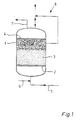
- the figure shows a schematic representation of the device.
- the device comprises a container 1, in which a first nozzle base 2 is arranged.
- a catalyst bed 3 is located above the bottom of the nozzle.
- the catalyst bed 3 When the device is out of operation, the catalyst bed 3 rests on the nozzle base 2. In the operating state shown, the catalyst bed 3 acts as a floating bed through which flow flows from bottom to top. It is sponged, laying against a second nozzle base 4, with an increasing density. It forms a lower floating bed layer, which contains approx. 20-25% of the catalyst material, and an upper fixed bed layer, which contains the rest of the catalyst material.
- the catalyst bed consists of polystyrene balls that have a palladium coating.
- the oxygen-laden water enters the container 1 through an inlet line 5 at the bottom.
- a hydrogen line 6 opens into the inlet line 5.
- the gaseous hydrogen which is under higher pressure than the oxygen-laden water, thus enters the container 1 together with it.
- the hydrogen When flowing through the catalyst bed 3 working as a floating bed, the hydrogen is intimately mixed with the water to be purified. The hydrogen goes completely into solution. This is the prerequisite for the hydrogen to be adsorbed on the palladium layer of the floating bed particles.
- the adsorbed hydrogen can with the in the water contained oxygen react, the only reaction product being water.
- the mixing and dissolving of the hydrogen and its adsorption are intensive and complete.
- the amount of hydrogen can therefore be set to the stoichiometric range.
- the efficiency of oxygen removal is correspondingly high, with a short reaction time.
- the catalyst bed also saturates very quickly when the device is started up.
- an outlet line 7 for purified water is connected to the container 1. Furthermore, the container 1 has a ventilation system 8, via which hydrogen can be drawn off in the event of a fault.
- the water and the hydrogen can be introduced separately into the lower area of the container.
- the container can be provided with additional mixing devices below the lower nozzle base.
- the ventilation system is an optional feature that may not be necessary. Instead of a single outlet line for purified water, several of them are also possible.
Landscapes
- Life Sciences & Earth Sciences (AREA)
- Hydrology & Water Resources (AREA)
- Engineering & Computer Science (AREA)
- Environmental & Geological Engineering (AREA)
- Water Supply & Treatment (AREA)
- Chemical & Material Sciences (AREA)
- Organic Chemistry (AREA)
- Removal Of Specific Substances (AREA)
- Catalysts (AREA)
- Devices And Processes Conducted In The Presence Of Fluids And Solid Particles (AREA)
Claims (5)
- Procédé pour l'élimination catalytique de l'oxygène dans l'eau, où de l'hydrogène est introduit dans l'eau et conduit à travers un lit de catalyseur, caractérisé an ce que l'eau est conduite du bas en haut à travers le lit du catalyseur, celui-ci étant utilisé à contre-courant en tant que lit flottant.
- Procédé selon la revendication 1, caractérisé en ce qu'à l'introduction de l'hydrogène dans l'eau, la pression de l'hydrogène est établie à une valeur plus élevée que celle de l'eau.
- Dispositif pour l'élimination catalytique de l'oxygène de l'eau, avecun récipient (1),un premier fond à tuyères (2), agencé dans le récipient,un lit de catalyseur (3) agencé dans le récipient, au-dessus du premier fond à tuyères,un dispositif d'amenée (5, 6), raccordé au récipient, pour l'eau chargée d'oxygène et l'hydrogèneet avec une conduite de sortie (7) raccordée au récipient pour l'eau épurée,
oùle dispositif d'amenée (5, 6) est raccordé en dessous du premier fond à tuyères et la conduite de sortie (7) au dessus du lit de catalyseur (3), au récipient (1). - Dispositif selon la revendication 3, caractérisé en ce que le récipient (1) présente, en dessous de la conduite de sortie (7) et au dessus du lit de catalyseur, (3) un second fond à tuyères (4).
- Dispositif selon la revendication 3 ou 4, caractérisé en ce que le dispositif d'amenée présente une conduite d'entrée (5) pour l'eau chargée d'oxygène, où débouche une conduite d'hydrogène (6).
Applications Claiming Priority (2)
| Application Number | Priority Date | Filing Date | Title |
|---|---|---|---|
| DE4315520 | 1993-05-10 | ||
| DE4315520A DE4315520A1 (de) | 1993-05-10 | 1993-05-10 | Verfahren und Vorrichtung zum katalytischen Entfernen von Sauerstoff aus Wasser |
Publications (2)
| Publication Number | Publication Date |
|---|---|
| EP0628516A1 EP0628516A1 (fr) | 1994-12-14 |
| EP0628516B1 true EP0628516B1 (fr) | 1997-07-23 |
Family
ID=6487693
Family Applications (1)
| Application Number | Title | Priority Date | Filing Date |
|---|---|---|---|
| EP94106743A Expired - Lifetime EP0628516B1 (fr) | 1993-05-10 | 1994-04-29 | Méthode et dispositif pour l'élimination catalytique de l'oxygène dissous dans l'eau |
Country Status (3)
| Country | Link |
|---|---|
| EP (1) | EP0628516B1 (fr) |
| AT (1) | ATE155763T1 (fr) |
| DE (2) | DE4315520A1 (fr) |
Families Citing this family (1)
| Publication number | Priority date | Publication date | Assignee | Title |
|---|---|---|---|---|
| DE102006022417A1 (de) * | 2006-05-13 | 2007-11-22 | Ast Gmbh | Aufbereitungsvorrichtung für eine Vorrichtung zur Erzeugung von Stoßwellen |
Family Cites Families (6)
| Publication number | Priority date | Publication date | Assignee | Title |
|---|---|---|---|---|
| DE365665C (de) * | 1916-04-12 | 1922-12-19 | Carl A Hartung | Verfahren zur Beseitigung von Sauerstoff aus Wasser |
| US3052527A (en) * | 1957-05-03 | 1962-09-04 | Smith Corp A O | Apparatus for removing dissolved oxygen from water |
| GB2149391B (en) * | 1983-11-10 | 1987-10-07 | Westinghouse Electric Corp | Method for removing dissolved oxygen from aqueous media |
| DE3735758A1 (de) * | 1987-10-22 | 1989-05-03 | Degussa | Verfahren zur katalytischen reduktion von sauerstoff in waessrigen medien |
| DE3830850A1 (de) * | 1988-09-10 | 1990-03-22 | Gutec Gmbh | Verfahren zur entfernung des nitrit- und/oder nitratgehaltes in wasser |
| DE4142502A1 (de) * | 1991-12-21 | 1993-06-24 | Solvay Umweltchemie Gmbh | Blasenfreier wasserstoffeintrag in waessrige fluessigkeiten |
-
1993
- 1993-05-10 DE DE4315520A patent/DE4315520A1/de not_active Ceased
-
1994
- 1994-04-29 DE DE59403429T patent/DE59403429D1/de not_active Expired - Fee Related
- 1994-04-29 AT AT94106743T patent/ATE155763T1/de not_active IP Right Cessation
- 1994-04-29 EP EP94106743A patent/EP0628516B1/fr not_active Expired - Lifetime
Also Published As
| Publication number | Publication date |
|---|---|
| ATE155763T1 (de) | 1997-08-15 |
| EP0628516A1 (fr) | 1994-12-14 |
| DE59403429D1 (de) | 1997-08-28 |
| DE4315520A1 (de) | 1994-11-17 |
Similar Documents
| Publication | Publication Date | Title |
|---|---|---|
| DE69313854T2 (de) | System und verfahren zur reinigung von stickstoff enthaltendem abwasser | |
| DE69630236T2 (de) | Methode und vorrichtung zur biologischen behandlung von organisch belastetem abwasser | |
| DE68922427T2 (de) | Verfahren zur Zurückgewinnung von sauerstoffreichem Gas. | |
| DE69627203T2 (de) | Flotationsvorrichtung und verfahren | |
| DD300818A5 (de) | Verfahren und anlage zur kontinuierlichen herstellung von spanplatten, faserplatten und dergleichen | |
| DE69517542T2 (de) | Verfahren zur Herstellung von Wasserstoffsuperoxyd und ein Reaktor für dieses Verfahren | |
| EP0065035A1 (fr) | Procédé et dispositif pour la dénitrification des eaux | |
| DD231337A5 (de) | Verfahren zur herstellung der suspension von flugaschen im wasser und die anlage zur realisierung dieses verfahrens | |
| DE2728554A1 (de) | Verfahren und vorrichtung fuer die nassoxidation von fluessigem abfallabwasser | |
| DE3410109C3 (de) | Vorrichtung zur nassen Entschwefelung von Rauchgasen | |
| DE69907633T2 (de) | Verfahren zur herstellung von wasserstoffperoxyd | |
| EP0628516B1 (fr) | Méthode et dispositif pour l'élimination catalytique de l'oxygène dissous dans l'eau | |
| DE3025653C2 (fr) | ||
| DE69817937T2 (de) | Beladene Ionenaustauscherharze, deren Herstellung und Verwendungen | |
| DE68908572T2 (de) | Verfahren zum Verringern des Hysteresiseffectes in einem Gasliftschlaufenreaktor mit suspendierten, festen Teilchen. | |
| DE60210204T2 (de) | Verfahren zur katalytischen Zersetzung von Distickstoffmonoxid (N2O) | |
| CH644569A5 (de) | Verfahren und vorrichtung zum behandeln von abwasser. | |
| DE1917899A1 (de) | Ionenaustausch im Abwaertsstrom | |
| EP0316569B1 (fr) | Procédé de réduction catalytique de l'oxygène dans les milieux aqueux | |
| DE69313852T2 (de) | Verfahren für die behandlung von wasser | |
| DE69002348T2 (de) | Vorrichtung und verfahren fuer eine kombinierte luft- und wasserreinigung. | |
| WO1995027566A1 (fr) | Procede et dispositif de separation de substances en suspension dans des fluides | |
| DE2604674A1 (de) | Hochwirksames belebtschlamm-verfahren | |
| EP0069800A1 (fr) | Procédé pour l'épuration d'eaux usées contenant de l'hydrazine | |
| DE19707425A1 (de) | Verfahren und Vorrichtung zum Eintrag von Sauerstoff in Wasser oder wässrigen Lösungen |
Legal Events
| Date | Code | Title | Description |
|---|---|---|---|
| PUAI | Public reference made under article 153(3) epc to a published international application that has entered the european phase |
Free format text: ORIGINAL CODE: 0009012 |
|
| 17P | Request for examination filed |
Effective date: 19940907 |
|
| AK | Designated contracting states |
Kind code of ref document: A1 Designated state(s): AT BE CH DE DK ES FR GB GR IE IT LI LU MC NL PT SE |
|
| 17Q | First examination report despatched |
Effective date: 19960221 |
|
| GRAG | Despatch of communication of intention to grant |
Free format text: ORIGINAL CODE: EPIDOS AGRA |
|
| GRAH | Despatch of communication of intention to grant a patent |
Free format text: ORIGINAL CODE: EPIDOS IGRA |
|
| GRAH | Despatch of communication of intention to grant a patent |
Free format text: ORIGINAL CODE: EPIDOS IGRA |
|
| GRAA | (expected) grant |
Free format text: ORIGINAL CODE: 0009210 |
|
| AK | Designated contracting states |
Kind code of ref document: B1 Designated state(s): AT BE CH DE DK ES FR GB GR IE IT LI LU MC NL PT SE |
|
| PG25 | Lapsed in a contracting state [announced via postgrant information from national office to epo] |
Ref country code: NL Free format text: LAPSE BECAUSE OF FAILURE TO SUBMIT A TRANSLATION OF THE DESCRIPTION OR TO PAY THE FEE WITHIN THE PRESCRIBED TIME-LIMIT Effective date: 19970723 Ref country code: IT Free format text: LAPSE BECAUSE OF FAILURE TO SUBMIT A TRANSLATION OF THE DESCRIPTION OR TO PAY THE FEE WITHIN THE PRESCRIBED TIME-LIMIT;WARNING: LAPSES OF ITALIAN PATENTS WITH EFFECTIVE DATE BEFORE 2007 MAY HAVE OCCURRED AT ANY TIME BEFORE 2007. THE CORRECT EFFECTIVE DATE MAY BE DIFFERENT FROM THE ONE RECORDED. Effective date: 19970723 Ref country code: GR Free format text: LAPSE BECAUSE OF FAILURE TO SUBMIT A TRANSLATION OF THE DESCRIPTION OR TO PAY THE FEE WITHIN THE PRESCRIBED TIME-LIMIT Effective date: 19970723 Ref country code: GB Effective date: 19970723 Ref country code: FR Effective date: 19970723 Ref country code: ES Free format text: THE PATENT HAS BEEN ANNULLED BY A DECISION OF A NATIONAL AUTHORITY Effective date: 19970723 Ref country code: DK Effective date: 19970723 |
|
| REF | Corresponds to: |
Ref document number: 155763 Country of ref document: AT Date of ref document: 19970815 Kind code of ref document: T |
|
| REG | Reference to a national code |
Ref country code: CH Ref legal event code: EP |
|
| REF | Corresponds to: |
Ref document number: 59403429 Country of ref document: DE Date of ref document: 19970828 |
|
| PG25 | Lapsed in a contracting state [announced via postgrant information from national office to epo] |
Ref country code: SE Effective date: 19971023 |
|
| PG25 | Lapsed in a contracting state [announced via postgrant information from national office to epo] |
Ref country code: PT Effective date: 19971031 |
|
| EN | Fr: translation not filed | ||
| NLV1 | Nl: lapsed or annulled due to failure to fulfill the requirements of art. 29p and 29m of the patents act | ||
| GBV | Gb: ep patent (uk) treated as always having been void in accordance with gb section 77(7)/1977 [no translation filed] |
Effective date: 19970723 |
|
| PG25 | Lapsed in a contracting state [announced via postgrant information from national office to epo] |
Ref country code: IE Free format text: LAPSE BECAUSE OF NON-PAYMENT OF DUE FEES Effective date: 19980330 |
|
| REG | Reference to a national code |
Ref country code: IE Ref legal event code: FD4D Ref document number: 75282 Country of ref document: IE |
|
| PG25 | Lapsed in a contracting state [announced via postgrant information from national office to epo] |
Ref country code: LU Free format text: LAPSE BECAUSE OF NON-PAYMENT OF DUE FEES Effective date: 19980429 Ref country code: AT Free format text: LAPSE BECAUSE OF NON-PAYMENT OF DUE FEES Effective date: 19980429 |
|
| PG25 | Lapsed in a contracting state [announced via postgrant information from national office to epo] |
Ref country code: LI Free format text: LAPSE BECAUSE OF NON-PAYMENT OF DUE FEES Effective date: 19980430 Ref country code: CH Free format text: LAPSE BECAUSE OF NON-PAYMENT OF DUE FEES Effective date: 19980430 Ref country code: BE Free format text: LAPSE BECAUSE OF NON-PAYMENT OF DUE FEES Effective date: 19980430 |
|
| PLBE | No opposition filed within time limit |
Free format text: ORIGINAL CODE: 0009261 |
|
| STAA | Information on the status of an ep patent application or granted ep patent |
Free format text: STATUS: NO OPPOSITION FILED WITHIN TIME LIMIT |
|
| 26N | No opposition filed | ||
| BERE | Be: lapsed |
Owner name: STEAG A.G. Effective date: 19980430 |
|
| PG25 | Lapsed in a contracting state [announced via postgrant information from national office to epo] |
Ref country code: MC Free format text: LAPSE BECAUSE OF NON-PAYMENT OF DUE FEES Effective date: 19981031 |
|
| REG | Reference to a national code |
Ref country code: CH Ref legal event code: PL |
|
| PGFP | Annual fee paid to national office [announced via postgrant information from national office to epo] |
Ref country code: DE Payment date: 19990322 Year of fee payment: 6 |
|
| PG25 | Lapsed in a contracting state [announced via postgrant information from national office to epo] |
Ref country code: DE Free format text: LAPSE BECAUSE OF NON-PAYMENT OF DUE FEES Effective date: 20010201 |