EP0628693A2 - Corner support, in particular for an at least pivotal bearing of a wing, a window, a door or similar - Google Patents
Corner support, in particular for an at least pivotal bearing of a wing, a window, a door or similar Download PDFInfo
- Publication number
- EP0628693A2 EP0628693A2 EP94108786A EP94108786A EP0628693A2 EP 0628693 A2 EP0628693 A2 EP 0628693A2 EP 94108786 A EP94108786 A EP 94108786A EP 94108786 A EP94108786 A EP 94108786A EP 0628693 A2 EP0628693 A2 EP 0628693A2
- Authority
- EP
- European Patent Office
- Prior art keywords
- corner
- groove
- angle
- wing
- corner bracket
- Prior art date
- Legal status (The legal status is an assumption and is not a legal conclusion. Google has not performed a legal analysis and makes no representation as to the accuracy of the status listed.)
- Granted
Links
Images
Classifications
-
- E—FIXED CONSTRUCTIONS
- E05—LOCKS; KEYS; WINDOW OR DOOR FITTINGS; SAFES
- E05D—HINGES OR SUSPENSION DEVICES FOR DOORS, WINDOWS OR WINGS
- E05D15/00—Suspension arrangements for wings
- E05D15/48—Suspension arrangements for wings allowing alternative movements
- E05D15/52—Suspension arrangements for wings allowing alternative movements for opening about a vertical as well as a horizontal axis
- E05D15/5214—Corner supports
-
- E—FIXED CONSTRUCTIONS
- E05—LOCKS; KEYS; WINDOW OR DOOR FITTINGS; SAFES
- E05Y—INDEXING SCHEME ASSOCIATED WITH SUBCLASSES E05D AND E05F, RELATING TO CONSTRUCTION ELEMENTS, ELECTRIC CONTROL, POWER SUPPLY, POWER SIGNAL OR TRANSMISSION, USER INTERFACES, MOUNTING OR COUPLING, DETAILS, ACCESSORIES, AUXILIARY OPERATIONS NOT OTHERWISE PROVIDED FOR, APPLICATION THEREOF
- E05Y2900/00—Application of doors, windows, wings or fittings thereof
- E05Y2900/10—Application of doors, windows, wings or fittings thereof for buildings or parts thereof
- E05Y2900/13—Type of wing
- E05Y2900/148—Windows
Definitions
- the invention relates to a corner bracket on or for a fitting part of a fitting, in particular for the at least rotatable mounting of a sash, a window, a door or the like on a fixed frame, the sash having at least in the region of the frame corner receiving the corner bracket is provided against the fixed frame towards the outside, widening the fitting part groove on the outside, the corner angle also resting on the two parallel shoulders of the fitting part groove and being fastened to the wing by means of screws screwed into the groove base.
- the fitting part groove usually runs around on the casement, so that one and the same profile can be used for the frame bars.
- the cross section of the fitting part groove depends on the fitting to be fitted.
- the step-by-step narrowing can, as provided in the exemplary embodiment, be achieved by providing two parallel, mutually facing webs shortly before the slot mouth.
- the corner angle then lies on the outer edge of the two webs, it again being customary for the corner angle to be flush with the wing on the outside.
- the corner bracket is used to attach fittings, for example a bearing sleeve of a pivot bearing for the at least rotatable mounting of this wing on a fixed frame receiving the latter.
- fittings for example a bearing sleeve of a pivot bearing for the at least rotatable mounting of this wing on a fixed frame receiving the latter.
- the width of the groove at the mouth of the groove generally corresponds to the width of the angle legs of the corner bracket, so that the groove at the corner in question is closed smoothly on the outside by the corner bracket.
- An extension plate can be attached to each angle leg, which then closes the remaining part of the groove on the outside.
- each leg of the corner angle of the known prior art has a certain distance from the base of the groove and the fastening screws penetrate the groove to the groove base and then penetrate into the groove base, whereby the connection to the relevant spar of the casement takes place, the load on the screws is particularly unfavorable. For example, if the sash in question is subjected to violence or if it heats up excessively with appropriate thermal expansion, the screws that are initially screwed in tightly can loosen a little, and this then leads to bending stress not only when subjected to violence but also when the window or door is subsequently used of the screws. As a result, at least some of the screws can loosen further, and this will result in an overall compromise in safety.
- the object is to develop a corner bracket of the type mentioned in such a way that, at least in the cases described, the bending stress on the screws is at least largely avoided.
- this corner bracket has, as it were, a supporting element for supporting on the base of the groove, which in addition to the non-deformed angled leg of at least one Fastening screw is penetrated.
- the screw is thus subjected to shear at the groove base and not to bending as before.
- a screw is always more resilient to shear than to a bend, and as a result, this corner angle, in the desired manner, brings about a significant improvement in safety when abnormal conditions occur, which also includes excessive heating of the wing.
- the width of the end areas must of course be chosen so that they fit through the respective narrow point between the two support edges in the groove and, if the groove narrows further inside, the passage to the groove base is also possible there. In most cases, the narrow point between the two support edges is the narrowest point of the groove, so that a one-time reduction in the width, in particular before bending, is sufficient.
- the total height of the angle legs in the region of the bent ends is equal to the total depth of the groove. It follows from this that the bent ends of the angled legs generally have an arcuate or U-shaped shape and the corner angle is not simply folded.
- a further development of the invention provides that the width of the corner angle in the area of the immediate corner corner is reduced by means of two opposite cutouts, the size of the cutouts corresponding approximately to the cross section of a weld bead on the outer corner of the frame.
- the depth of the cutouts can correspond approximately to the reduction in the width on each side of the end region to be bent or, in other words, the width of the corner angle in the region of the immediate corner corner is approximately equal to the width of the two bent end regions.
- the bearing sleeve can be connected indirectly via an angular intermediate member to the upper angle leg in the position of use, whereby an articulated connection known per se can also be present, so that the bearing sleeve can be pivoted relative to the sash frame level.
- the corner bracket 1 forms the one in the embodiment together with a bearing sleeve 2 or the wing-side half of a lower pivot bearing 3.
- the wing 4 is rotatably supported in a manner not shown with the help of an upper and the lower pivot bearing on a fixed frame. It can also be a turn-tilt wing.
- the corner angle has two angle legs 5 and 6, which are normally perpendicular to one another.
- the lower, horizontal angle leg 6 in the use position is shorter than the vertical angle leg 5. This is common with such corner angles, but this does not rule out that both angle legs are the same are long.
- the end regions 7 and 8 of the two angle legs are bent inwards by approximately 180 °.
- these end regions are not simply folded; rather, together with the part of the respective angle leg that has remained undeformed, they form cross-sectionally arched or U-shaped supporting elements.
- Figure 2 which represents the angle leg before bending, it can be seen that the width of the corner angle material is reduced at the two ends.
- the reduced part forms a support element 9 or 10 after the two bends by 90 ° each, with which the corner angle on the groove base 11 of a groove 12 of the vertical frame spar 14 and a horizontal groove 13 of the supports horizontal spar 15 of the wing 4. It can be seen from FIG.
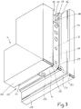
- each angled leg rests on the outwardly facing edge 16 of two mutually facing strips 17, the space between the two strips, of which only the right one can be seen in FIG. 3, forms a groove constriction 18.
- the outer surface of the two angle legs each runs flush with the associated spar surface 19 and 20.
- the grooves 12 and 13 are fitting grooves which, for example, accommodate drive rods in a known manner. Due to the mentioned narrowing of the groove, one can also speak of a fitting part groove 12 or 13 which is widened in sections on the outside. Moreover, it is common for the fitting part grooves 12 and 13 to be parts of a circumferential fitting part groove of the wing 4.
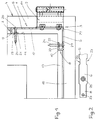
- the free end 21 or 22 of the bent end region 7 or 8 runs approximately parallel to the undeformed part of its angle leg 5 or 6 and is supported directly on the groove base 11.
- the free end 21 or 22 is provided with a through hole 23 for the passage of a fastening screw 24, which also passes through a coaxial through hole 25 of the undeformed angled leg and enters the material of the associated frame spar at the groove base.
- a cutout 26 or 27 is provided on both sides, that is, at the location of the corner angle 1, which forms the immediate corner corner 29 after bending.
- the width of the corner angle is approximately equal to that of the end regions 7 and 8.
Landscapes
- Engineering & Computer Science (AREA)
- Mechanical Engineering (AREA)
- Hinges (AREA)
- Wing Frames And Configurations (AREA)
- Joining Of Corner Units Of Frames Or Wings (AREA)
- Assembled Shelves (AREA)
- Door And Window Frames Mounted To Openings (AREA)
Abstract
Description
Die Erfindung bezieht sich auf einen Eckwinkel an einem oder für ein Beschlagteil eines Beschlags, insbesondere für die wenigstens drehbare Lagerung eines Flügels, eines Fensters, einer Tür oder dergleichen an einem festen Rahmen, wobei der Flügel zumindest im Bereich der den Eckwinkel aufnehmenden Rahmenecke mit einer gegen den festen Rahmen hin offenen, außen absatzweise verbreiterten Beschlagteilnut versehen ist, wobei des weiteren der Eckwinkel auf den beiden parallelen Absätzen der Beschlagteilnut aufliegt und er mittels in den Nutgrund eingedrehter Schrauben am Flügel befestigt ist. Aus fertigungstechnischen Gründen läuft die Beschlagteilnut in aller Regel am Flügelrahmen um, so daß man für die Rahmenholme ein und dasselbe Profil verwenden kann. Der Querschnitt der Beschlagteilnut richtet sich nach dem anzumontierenden Beschlag. Die absatzweise Verengung kann, wie beim Ausführungsbeispiel vorgesehen, dadurch erreicht werden, daß man kurz vor der Nutmündung zwei parallele, gegeneinander weisende Stege vorsieht. An der Außenkante der beiden Stege liegt dann der Eckwinkel auf, wobei es wiederum üblich ist, daß der Eckwinkel außen bündig mit dem Flügel abschließt.The invention relates to a corner bracket on or for a fitting part of a fitting, in particular for the at least rotatable mounting of a sash, a window, a door or the like on a fixed frame, the sash having at least in the region of the frame corner receiving the corner bracket is provided against the fixed frame towards the outside, widening the fitting part groove on the outside, the corner angle also resting on the two parallel shoulders of the fitting part groove and being fastened to the wing by means of screws screwed into the groove base. For manufacturing reasons, the fitting part groove usually runs around on the casement, so that one and the same profile can be used for the frame bars. The cross section of the fitting part groove depends on the fitting to be fitted. The step-by-step narrowing can, as provided in the exemplary embodiment, be achieved by providing two parallel, mutually facing webs shortly before the slot mouth. The corner angle then lies on the outer edge of the two webs, it again being customary for the corner angle to be flush with the wing on the outside.
Der Eckwinkel dient wie gesagt zum Anbringen von Beschlagteilen, also beispielsweise einer Lagerhülse eines Drehlagers für die zumindest drehbare Lagerung dieses Flügels an einem letzteren aufnehmenden festen Rahmen. Hierbei ist es im Hinblick auf die erfindungsgemäße Ausbildung des Eckwinkels unerheblich, auf welche Art und Weise der Eckwinkel und das wenigstens eine Beschlagteil des Fenster- oder Türbeschlags damit verbunden ist. Die Nutbreite an der Nutmündung entspricht in aller Regel der Breite der Winkelschenkel des Eckwinkels, so daß die Nut an der betreffenden Ecke durch den Eckwinkel außen glatt verschlossen wird. An jeden Winkelschenkel kann sich in Verlängerung eine Stulpschiene anschließen, welche dann den restlichen Teil der Nut außen verschließt.As I said, the corner bracket is used to attach fittings, for example a bearing sleeve of a pivot bearing for the at least rotatable mounting of this wing on a fixed frame receiving the latter. With regard to the design of the corner bracket according to the invention, it is irrelevant in what way the corner bracket and the at least one fitting part of the window or door fitting is connected to it. The width of the groove at the mouth of the groove generally corresponds to the width of the angle legs of the corner bracket, so that the groove at the corner in question is closed smoothly on the outside by the corner bracket. An extension plate can be attached to each angle leg, which then closes the remaining part of the groove on the outside.
Weil jeder Schenkel des Eckwinkels des bekannten Standes der Technik vom Nutgrund einen bestimmten Abstand aufweist und die Befestigungsschrauben die Nut bis zum Nutgrund hin durchsetzen und dann in den Nutgrund eindringen, wodurch die Verbindung mit dem betreffenden Holm des Flügelrahmens erfolgt, ist die Belastung der Schrauben besonders ungünstig. Beispielsweise bei einer Gewalteinwirkung auf den betreffenden Flügel oder bei einer starken Erhitzung mit entsprechender Wärmedehnung können sich die zunächst fest eingedrehten Schrauben etwas lockern, und dies führt dann nicht nur bei der Gewalteinwirkung, sondern auch bei der nachfolgenden Benutzung des Fensters oder der Tür zu einer Biegebeanspruchung der Schrauben. Als Folge davon kann sich zumindest ein Teil der Schrauben weiter lockern, und dies führt dann insgesamt zu einer Beeinträchtigung der Sicherheit.Because each leg of the corner angle of the known prior art has a certain distance from the base of the groove and the fastening screws penetrate the groove to the groove base and then penetrate into the groove base, whereby the connection to the relevant spar of the casement takes place, the load on the screws is particularly unfavorable. For example, if the sash in question is subjected to violence or if it heats up excessively with appropriate thermal expansion, the screws that are initially screwed in tightly can loosen a little, and this then leads to bending stress not only when subjected to violence but also when the window or door is subsequently used of the screws. As a result, at least some of the screws can loosen further, and this will result in an overall compromise in safety.
Es liegt die Aufgabe vor, einen Eckwinkel der eingangs genannten Art so weiterzubilden, daß zumindest in den geschilderten Fällen, die Biegebeanspruchung der Schrauben zumindest weitgehend vermieden wird.The object is to develop a corner bracket of the type mentioned in such a way that, at least in the cases described, the bending stress on the screws is at least largely avoided.
Zur Lösung dieser Aufgabe wird erfindungsgemäß vorgeschlagen, daß der Eckwinkel gemäß dem Oberbegriff des Anspruchs 1 entsprechend dem kennzeichnenden Teil dieses Anspruchs ausgebildet ist. Dieser Eckwinkel besitzt am Ende seiner Winkelschenkel gewissermaßen je ein Abstützelement zum Abstützen am Nutgrund, welches zusätzlich zum unverformt gebliebenen Winkelschenkel von wenigstens einer Befestigungsschraube durchsetzt wird. Die Schraube wird somit am Nutgrund auf Abscheren und nicht wie bisher, auf Biegung beansprucht. Auf Abscheren ist eine Schraube immer höher belastbar als auf Biegung, und infolgedessen bringt dieser Eckwinkel in der angestrebten Weise eine wesentliche Verbesserung der Sicherheit, wenn anormale Verhältnisse auftreten, worunter auch eine starke Erwärmung des Flügels fällt.To achieve this object it is proposed according to the invention that the corner angle is designed according to the preamble of
Die Breite der Endbereiche muß selbstverständlich so gewählt werden, daß sie durch die jeweilige Engstelle zwischen den beiden Abstützrändern in der Nut hindurchpassen und, falls sich die Nut innen noch weiter verengt, auch dort der Durchtritt bis hin zum Nutgrund möglich ist. In den meisten Fällen ist die Engstelle zwischen den beiden Auflagerändern die engste Stelle der Nut, so daß eine einmalige Verringerung der Breite, insbesondere vor dem Umbiegen, ausreicht.The width of the end areas must of course be chosen so that they fit through the respective narrow point between the two support edges in the groove and, if the groove narrows further inside, the passage to the groove base is also possible there. In most cases, the narrow point between the two support edges is the narrowest point of the groove, so that a one-time reduction in the width, in particular before bending, is sufficient.
Wenn der Eckwinkel außen bündig mit der die Nut aufweisenden Fläche des Flügels abschließt, so ist die Gesamthöhe der Winkelschenkel im Bereich der umgebogenen Enden gleich der Gesamttiefe der Nut. Hieraus folgt, daß in aller Regel die umgebogenen Enden der Winkelschenkel eine bogen- oder U-förmige Gestalt aufweisen und der Eckwinkel nicht einfach gefaltet ist.If the corner angle is flush on the outside with the surface of the wing which has the groove, the total height of the angle legs in the region of the bent ends is equal to the total depth of the groove. It follows from this that the bent ends of the angled legs generally have an arcuate or U-shaped shape and the corner angle is not simply folded.
Eine Weiterbildung der Erfindung sieht vor, daß die Breite des Eckwinkels im Bereich der unmittelbaren Winkelecke mittels zweier gegenüberliegender Freisparungen reduziert ist, wobei die Größe der Freisparungen etwa dem Querschnitt einer Schweißwulst an der Außenecke des Rahmens entspricht. Wie das Ausführungsbeispiel zeigt, kann die Tiefe der Freisparungen etwa der Verringerung der Breite an jeder Seite des umzubiegenden Endbereichs entsprechen oder, anders ausgedrückt, ist die Breite des Eckwinkels im Bereich der unmittelbaren Winkelecke etwa gleich der Breite der beiden umgebogenen Endbereiche.A further development of the invention provides that the width of the corner angle in the area of the immediate corner corner is reduced by means of two opposite cutouts, the size of the cutouts corresponding approximately to the cross section of a weld bead on the outer corner of the frame. As the exemplary embodiment shows, the depth of the cutouts can correspond approximately to the reduction in the width on each side of the end region to be bent or, in other words, the width of the corner angle in the region of the immediate corner corner is approximately equal to the width of the two bent end regions.
Wenn der Flügelrahmen aus Kunststoffprofilen hergestellt wird, so führt dies in der Regel zu einer Schweißwulst an jeder Rahmenecke, falls die Rahmenholme auf Gehrung gearbeitet und durch bekannte Verfahren im Gehrungsbereich miteinander verschweißt werden. Durch die Freisparungen bzw. die hieraus resultierende Verringerung der Breite an der unmittelbaren Winkelecke, also am Übergang vom einen Winkelschenkel zum anderen, schafft man ausreichend Raum für die Schweißwülste, so daß diese beim Festschrauben des Eckwinkels weder zusammengedrückt noch beschädigt werden. Auch dies kommt der Sicherheit zugute. Gemäß einer weiteren Ausgestaltung der Erfindung wird vorgeschlagen, daß an dem in den Gebrauchslage vertikalen Winkelschenkel die eine Hälfte eines Drehlagers, insbesondere mindestens eine Lagerhülse angebracht ist. Auf die Verbindung dieser Lagerhülse mit dem Eckwinkel kommt es im einzelnen nicht an. Wenn es sich beispielsweise um einen oberen Eckwinkel für einen Dreh-Kipp-Beschlag handelt, so kann die Lagerhülse indirekt über ein winkelförmiges Zwischenglied mit dem in Gebrauchslage oberen Winkelschenkel verbunden sein, wobei außerdem noch eine an sich bekannte gelenkige Verbindung vorhanden sein kann, so daß die Lagerhülse gegenüber der Flügelrahmenebene verschwenkt werden kann.If the casement is made from plastic profiles, this usually leads to a weld bead on each corner of the frame if the frame spars are mitred and welded to each other in the miter area by known methods. The cutouts or the resulting reduction in the width at the immediate corner, i.e. at the transition from one angle leg to the other, create sufficient space for the welding beads so that they are neither compressed nor damaged when the corner angle is screwed on. This also benefits security. According to a further embodiment of the invention, it is proposed that one half of a rotary bearing, in particular at least one bearing sleeve, is attached to the angle leg that is vertical in the position of use. On connecting this Bearing sleeves with the corner bracket are not important. If, for example, there is an upper corner bracket for a turn-tilt fitting, the bearing sleeve can be connected indirectly via an angular intermediate member to the upper angle leg in the position of use, whereby an articulated connection known per se can also be present, so that the bearing sleeve can be pivoted relative to the sash frame level.
Die Erfindung wird nachstehend anhand der Zeichnung näher erläutert. Die Zeichnung zeigt dieses Ausführungsbeispiel. Hierbei stellen dar:
Figur 1- eine Seitenansicht des an einer unteren Flügelecke anmontierten, erfindungsgemäß ausgebildeten Eckwinkels;
Figur 2- den einen Winkelschenkel dieses Eckwinkels vor dem Biegen;
Figur 3- in perspektivischer Darstellung die genannten Winkelecke mit dem anmontierten Eckwinkel, jedoch ohne Befestigungsschrauben.
- Figure 1
- a side view of the corner angle mounted on a lower wing corner, designed according to the invention;
- Figure 2
- one angle leg of this corner angle before bending;
- Figure 3
- a perspective view of the mentioned corner with the corner bracket installed, but without fastening screws.
Der erfindungsgemäße Eckwinkel 1 bildet beim Ausführungsbeispiel zusammen mit einer Lagerhülse 2 die eine bzw. die flügelseitige Hälfte eines unteren Drehlagers 3. Der Flügel 4 ist in nicht näher dargestellter Weise mit Hilfe eines oberen und des unteren Drehlagers drehbar an einem festen Rahmen gelagert. Es kann sich auch um einen Dreh-Kipp-Flügel handeln.The
Der Eckwinkel besitzt zwei im Normalfalle rechtwinklig zueinander verlaufende Winkelschenkel 5 und 6. Dabei ist beim Ausführungsbeispiel der in Gebrauchslage untere, horizontale Winkelschenkel 6 kürzer als der vertikale Winkelschenkel 5. Dies ist bei solchen Eckwinkeln üblich, jedoch schließt das nicht aus, daß beide Winkelschenkel gleich lang sind.The corner angle has two
Erfindungsgemäß sind die Endbereiche 7 und 8 der beiden Winkelschenkel nach innen hin um etwa 180° umgebogen. Diese Endbereiche sind aber beim Ausführungsbeispiel nicht einfach gefaltet, vielmehr bilden sie zusammen mit dem unverformt gebliebenen Teil des jeweiligen Winkelschenkels im Querschnitt bogen- oder U-förmige Abstützelemente. Aus der Abwicklung der Figur 2, welche den Winkelschenkel vor dem Biegen darstellt, erkennt man, daß die Breite des Eckwinkelmaterials an den beiden Enden reduziert ist. Der reduzierte Teil bildet nach dem zweimaligen Umbiegen um jeweils 90° ein Abstützelement 9 bzw. 10, mit welchen sich der Eckwinkel am Nutgrund 11 einer Nut 12 des vertikalen Rahmenholms 14 und einer horizontalen Nut 13 des horizontalen Holms 15 des Flügels 4 abstützt. Aus Figur 3 ergibt sich, daß der breitere, unverformt gebliebene Teil jedes Winkelschenkels an der nach außen weisenden Kante 16 zweier gegeneinander weisender Leisten 17 aufliegt, wobei der Zwischenraum zwischen den beiden Leisten, von denen in Figur 3 jeweils nur die rechte zu sehen ist, eine Nutverengung 18 bildet. Die Außenfläche der beiden Winkelschenkel verläuft jeweils bündig mit der zugeordneten Holmfläche 19 bzw. 20. Bei den Nuten 12 und 13 handelt es sich um Beschlagteilnuten, welche in bekannter Weise beispielsweise Treibstangen aufnehmen. Aufgrund der erwähnten Nutverengung kann man auch von einer außen absatzweise verbreiterten Beschlagteilnut 12 bzw. 13 sprechen. Im übrigen ist es üblich, daß die Beschlagteilnuten 12 und 13 Teile einer umlaufenden Beschlagteilnut des Flügels 4 sind.According to the invention, the
Aus Figur 1 ergibt sich, daß das freie Ende 21 bzw. 22 des umgebogenen Endbereichs 7 bzw. 8 etwa parallel zum unverformten Teil seines Winkelschenkels 5 bzw. 6 verläuft und sich unmittelbar am Nutgrund 11 abstützt. Das freie Ende 21 bzw. 22 ist mit einer Durchgangsbohrung 23 für den Durchtritt einer Befestigungsschraube 24 versehen, welche auch noch eine hierzu koaxiale Durchgangsbohrung 25 des unverformten Winkelschenkels durchsetzt und am Nutgrund in das Material des zugeordneten Rahmenholms eintritt.It can be seen from FIG. 1 that the
Aus Figur 2 ergibt sich, daß am Übergang vom vertikalen Winkelschenkel 5 zum horizontalen Winkelschenkel 6 beidseits je eine Freisparung 26 bzw. 27 vorgesehen ist, also an der Stelle des Eckwinkels 1, welche nach dem Biegen die unmittelbare Winkelecke 29 bildet. Im Bereich dieser Freisparungen ist die Breite des Eckwinkels etwa gleich derjenigen der Endbereiche 7 und 8. Wenn der Rahmen des Flügels 4 aus vier auf Gehrung gearbeiteten Holmen besteht und es sich dabei um Kunststoffprofile handelt, die beispielsweise mittels Ultraschall zusammengeschweißt werden, so entsteht an jeder Ecke eine Schweißwulst 30. Durch die Freisparung erreicht man, daß diese Wulst im Bereich der Beschlagteilnut 13 bzw. 14 durch den Eckwinkel 1 nicht zusammengedrückt und erst recht nicht beschädigt wird, sondern frei unter dieser Ecke 29 hindurchlaufen kann.From Figure 2 it follows that at the transition from the
Claims (3)
Applications Claiming Priority (2)
| Application Number | Priority Date | Filing Date | Title |
|---|---|---|---|
| DE9308670U | 1993-06-10 | ||
| DE9308670U DE9308670U1 (en) | 1993-06-10 | 1993-06-10 | Corner bracket, in particular for the at least rotatable mounting of a wing, a window, a door or the like. |
Publications (4)
| Publication Number | Publication Date |
|---|---|
| EP0628693A2 true EP0628693A2 (en) | 1994-12-14 |
| EP0628693A3 EP0628693A3 (en) | 1995-06-14 |
| EP0628693B1 EP0628693B1 (en) | 1996-11-20 |
| EP0628693B2 EP0628693B2 (en) | 2006-01-04 |
Family
ID=6894266
Family Applications (1)
| Application Number | Title | Priority Date | Filing Date |
|---|---|---|---|
| EP94108786A Expired - Lifetime EP0628693B2 (en) | 1993-06-10 | 1994-06-08 | Corner support, in particular for an at least pivotal bearing of a wing, a window, a door or similar |
Country Status (4)
| Country | Link |
|---|---|
| EP (1) | EP0628693B2 (en) |
| AT (1) | ATE145446T1 (en) |
| DE (2) | DE9308670U1 (en) |
| ES (1) | ES2095702T5 (en) |
Cited By (1)
| Publication number | Priority date | Publication date | Assignee | Title |
|---|---|---|---|---|
| DE29707358U1 (en) * | 1997-04-23 | 1998-08-27 | Ferco International Ferrures et Serrures de Bâtiment S.A., Reding | Fitting with support arm or extension arm for mounting a rotating sash or tilt-and-turn sash |
Families Citing this family (2)
| Publication number | Priority date | Publication date | Assignee | Title |
|---|---|---|---|---|
| DE29511756U1 (en) * | 1995-07-20 | 1995-09-28 | Ferco International Usine de Ferrures de Bâtiment S.A.R.L., Sarrebourg | Wing-side corner bearing fitting for tilt and turn windows |
| DE19707496A1 (en) * | 1997-02-25 | 1998-08-27 | Winkhaus Fa August | Wing bearing part |
Family Cites Families (3)
| Publication number | Priority date | Publication date | Assignee | Title |
|---|---|---|---|---|
| DE8413144U1 (en) † | 1984-04-28 | 1984-07-26 | Gretsch-Unitas GmbH Baubeschläge, 7257 Ditzingen | WING-SIDED HINGE FOR ONE WINDOW, ONE DOOR OR. DGL. |
| DE8516560U1 (en) * | 1985-06-07 | 1985-07-18 | Siegenia-Frank Kg, 5900 Siegen | Opening device for the sash of windows, doors or the like. |
| DE4102295C1 (en) † | 1991-01-26 | 1992-03-12 | August Bilstein Gmbh & Co. Kg, 5828 Ennepetal, De |
-
1993
- 1993-06-10 DE DE9308670U patent/DE9308670U1/en not_active Expired - Lifetime
-
1994
- 1994-06-08 AT AT94108786T patent/ATE145446T1/en not_active IP Right Cessation
- 1994-06-08 EP EP94108786A patent/EP0628693B2/en not_active Expired - Lifetime
- 1994-06-08 DE DE59401063T patent/DE59401063D1/en not_active Expired - Fee Related
- 1994-06-08 ES ES94108786T patent/ES2095702T5/en not_active Expired - Lifetime
Cited By (1)
| Publication number | Priority date | Publication date | Assignee | Title |
|---|---|---|---|---|
| DE29707358U1 (en) * | 1997-04-23 | 1998-08-27 | Ferco International Ferrures et Serrures de Bâtiment S.A., Reding | Fitting with support arm or extension arm for mounting a rotating sash or tilt-and-turn sash |
Also Published As
| Publication number | Publication date |
|---|---|
| ES2095702T3 (en) | 1997-02-16 |
| EP0628693A3 (en) | 1995-06-14 |
| ATE145446T1 (en) | 1996-12-15 |
| EP0628693B1 (en) | 1996-11-20 |
| DE9308670U1 (en) | 1994-10-27 |
| DE59401063D1 (en) | 1997-01-02 |
| ES2095702T5 (en) | 2006-06-01 |
| EP0628693B2 (en) | 2006-01-04 |
Similar Documents
| Publication | Publication Date | Title |
|---|---|---|
| EP3504391B1 (en) | Hinge assembly for a switchboard enclosure and a corresponding switchboard enclosure | |
| DE2420688A1 (en) | Coupling froor woodden rfframe eellements - has externally threaded couplinn gg bolt with smooth end section haina1 receive wedge plate | |
| EP1255012B1 (en) | Device for fixing an element to an extruded profile | |
| EP0628693B1 (en) | Corner support, in particular for an at least pivotal bearing of a wing, a window, a door or similar | |
| EP2935742A1 (en) | Door system | |
| DE2460402B2 (en) | Opening device for tilt and turn sashes of windows, doors or the like. | |
| EP0947654A1 (en) | Concealed hinge | |
| EP0740043A2 (en) | Door arrangement with right and left rabbet with surround and door leaf | |
| EP2065546B2 (en) | Hinge fitting for pivotable mounting of the frame of a shutter | |
| DE2703060A1 (en) | ADJUSTABLE SUSPENSION FOR DOORS OR DGL. | |
| EP1001124B1 (en) | Hinge fitting for a shutter | |
| EP0312738B1 (en) | Mounting for a wing of a window, door or the like swinging out at least at the bottom and window or door equipped with that mounting | |
| EP1441096B1 (en) | Fixing device for a fitting | |
| EP1849944A2 (en) | Hinge fitting for pivotable mounting of a frame, especially a frame of a shutter | |
| DE202011052447U1 (en) | Arrangement of a drive unit of an opening or locking device | |
| EP1391576B1 (en) | Torsion compensation for wings movable from one plane to another parallel plane | |
| DE10005074C2 (en) | Device for arrangement in a gap between a frame and a wing | |
| EP3348731B1 (en) | Post and crossmember structure | |
| DE29811017U1 (en) | Attachment of a fitting part | |
| EP3204584B1 (en) | Angular fitting | |
| DE102005053650B3 (en) | Hinge for aluminium window frame has hinge tube mounted on plate with profiled clamp to engage edge of window frame | |
| EP4446552B1 (en) | Wing that can be displaced relative to a fixed frame of a window or a door and method for fixing two main profiles | |
| DE2013319A1 (en) | Sealing device for swing or turning sash of windows, doors or the like | |
| DE19927719A1 (en) | Draught excluder for insertion between frame and window or door comprises first section attached to frame and second section attached to window or door, first section being deformable and adjusted after installation to produce seal | |
| EP2025845A1 (en) | Hinge fitings of a window, door or similar with inclined pin |
Legal Events
| Date | Code | Title | Description |
|---|---|---|---|
| PUAI | Public reference made under article 153(3) epc to a published international application that has entered the european phase |
Free format text: ORIGINAL CODE: 0009012 |
|
| AK | Designated contracting states |
Kind code of ref document: A2 Designated state(s): AT BE CH DE ES FR GB IT LI NL |
|
| PUAL | Search report despatched |
Free format text: ORIGINAL CODE: 0009013 |
|
| AK | Designated contracting states |
Kind code of ref document: A3 Designated state(s): AT BE CH DE ES FR GB IT LI NL |
|
| 17P | Request for examination filed |
Effective date: 19950629 |
|
| GRAG | Despatch of communication of intention to grant |
Free format text: ORIGINAL CODE: EPIDOS AGRA |
|
| GRAH | Despatch of communication of intention to grant a patent |
Free format text: ORIGINAL CODE: EPIDOS IGRA |
|
| 17Q | First examination report despatched |
Effective date: 19960416 |
|
| GRAH | Despatch of communication of intention to grant a patent |
Free format text: ORIGINAL CODE: EPIDOS IGRA |
|
| GRAA | (expected) grant |
Free format text: ORIGINAL CODE: 0009210 |
|
| AK | Designated contracting states |
Kind code of ref document: B1 Designated state(s): AT BE CH DE ES FR GB IT LI NL |
|
| REF | Corresponds to: |
Ref document number: 145446 Country of ref document: AT Date of ref document: 19961215 Kind code of ref document: T |
|
| ITF | It: translation for a ep patent filed | ||
| REG | Reference to a national code |
Ref country code: CH Ref legal event code: NV Representative=s name: TROESCH SCHEIDEGGER WERNER AG |
|
| GBT | Gb: translation of ep patent filed (gb section 77(6)(a)/1977) |
Effective date: 19961115 |
|
| REF | Corresponds to: |
Ref document number: 59401063 Country of ref document: DE Date of ref document: 19970102 |
|
| ET | Fr: translation filed | ||
| REG | Reference to a national code |
Ref country code: ES Ref legal event code: FG2A Ref document number: 2095702 Country of ref document: ES Kind code of ref document: T3 |
|
| PLBI | Opposition filed |
Free format text: ORIGINAL CODE: 0009260 |
|
| PLBF | Reply of patent proprietor to notice(s) of opposition |
Free format text: ORIGINAL CODE: EPIDOS OBSO |
|
| 26 | Opposition filed |
Opponent name: SIEGENIA-FRANK KG Effective date: 19970816 |
|
| NLR1 | Nl: opposition has been filed with the epo |
Opponent name: SIEGENIA-FRANK KG |
|
| PLBF | Reply of patent proprietor to notice(s) of opposition |
Free format text: ORIGINAL CODE: EPIDOS OBSO |
|
| REG | Reference to a national code |
Ref country code: GB Ref legal event code: IF02 |
|
| PLAB | Opposition data, opponent's data or that of the opponent's representative modified |
Free format text: ORIGINAL CODE: 0009299OPPO |
|
| R26 | Opposition filed (corrected) |
Opponent name: SIEGENIA-AUBI KG Effective date: 19970816 |
|
| PLBC | Reply to examination report in opposition received |
Free format text: ORIGINAL CODE: EPIDOSNORE3 |
|
| PUAH | Patent maintained in amended form |
Free format text: ORIGINAL CODE: 0009272 |
|
| STAA | Information on the status of an ep patent application or granted ep patent |
Free format text: STATUS: PATENT MAINTAINED AS AMENDED |
|
| 27A | Patent maintained in amended form |
Effective date: 20060104 |
|
| AK | Designated contracting states |
Kind code of ref document: B2 Designated state(s): AT BE CH DE ES FR GB IT LI NL |
|
| GBTA | Gb: translation of amended ep patent filed (gb section 77(6)(b)/1977) | ||
| REG | Reference to a national code |
Ref country code: CH Ref legal event code: AEN Free format text: AUFRECHTERHALTUNG DES PATENTES IN GEAENDERTER FORM |
|
| NLR2 | Nl: decision of opposition |
Effective date: 20060104 |
|
| NLR3 | Nl: receipt of modified translations in the netherlands language after an opposition procedure | ||
| REG | Reference to a national code |
Ref country code: ES Ref legal event code: DC2A Date of ref document: 20060216 Kind code of ref document: T5 |
|
| ET3 | Fr: translation filed ** decision concerning opposition | ||
| PGFP | Annual fee paid to national office [announced via postgrant information from national office to epo] |
Ref country code: NL Payment date: 20070615 Year of fee payment: 14 Ref country code: CH Payment date: 20070615 Year of fee payment: 14 |
|
| PGFP | Annual fee paid to national office [announced via postgrant information from national office to epo] |
Ref country code: AT Payment date: 20070618 Year of fee payment: 14 |
|
| PGFP | Annual fee paid to national office [announced via postgrant information from national office to epo] |
Ref country code: ES Payment date: 20070628 Year of fee payment: 14 |
|
| PGFP | Annual fee paid to national office [announced via postgrant information from national office to epo] |
Ref country code: GB Payment date: 20070621 Year of fee payment: 14 |
|
| PGFP | Annual fee paid to national office [announced via postgrant information from national office to epo] |
Ref country code: IT Payment date: 20070626 Year of fee payment: 14 |
|
| PGFP | Annual fee paid to national office [announced via postgrant information from national office to epo] |
Ref country code: BE Payment date: 20070711 Year of fee payment: 14 |
|
| PGFP | Annual fee paid to national office [announced via postgrant information from national office to epo] |
Ref country code: FR Payment date: 20070615 Year of fee payment: 14 |
|
| PGFP | Annual fee paid to national office [announced via postgrant information from national office to epo] |
Ref country code: DE Payment date: 20080620 Year of fee payment: 15 |
|
| BERE | Be: lapsed |
Owner name: *GRETSCH-UNITAS G.M.B.H. BAUBESCHLAGE Effective date: 20080630 |
|
| REG | Reference to a national code |
Ref country code: CH Ref legal event code: PL |
|
| GBPC | Gb: european patent ceased through non-payment of renewal fee |
Effective date: 20080608 |
|
| NLV4 | Nl: lapsed or anulled due to non-payment of the annual fee |
Effective date: 20090101 |
|
| PG25 | Lapsed in a contracting state [announced via postgrant information from national office to epo] |
Ref country code: BE Free format text: LAPSE BECAUSE OF NON-PAYMENT OF DUE FEES Effective date: 20080630 |
|
| REG | Reference to a national code |
Ref country code: FR Ref legal event code: ST Effective date: 20090228 |
|
| PG25 | Lapsed in a contracting state [announced via postgrant information from national office to epo] |
Ref country code: AT Free format text: LAPSE BECAUSE OF NON-PAYMENT OF DUE FEES Effective date: 20080608 |
|
| PG25 | Lapsed in a contracting state [announced via postgrant information from national office to epo] |
Ref country code: NL Free format text: LAPSE BECAUSE OF NON-PAYMENT OF DUE FEES Effective date: 20090101 |
|
| PG25 | Lapsed in a contracting state [announced via postgrant information from national office to epo] |
Ref country code: LI Free format text: LAPSE BECAUSE OF NON-PAYMENT OF DUE FEES Effective date: 20080630 Ref country code: GB Free format text: LAPSE BECAUSE OF NON-PAYMENT OF DUE FEES Effective date: 20080608 Ref country code: CH Free format text: LAPSE BECAUSE OF NON-PAYMENT OF DUE FEES Effective date: 20080630 |
|
| REG | Reference to a national code |
Ref country code: ES Ref legal event code: FD2A Effective date: 20080609 |
|
| PG25 | Lapsed in a contracting state [announced via postgrant information from national office to epo] |
Ref country code: IT Free format text: LAPSE BECAUSE OF NON-PAYMENT OF DUE FEES Effective date: 20080608 Ref country code: FR Free format text: LAPSE BECAUSE OF NON-PAYMENT OF DUE FEES Effective date: 20080630 |
|
| PG25 | Lapsed in a contracting state [announced via postgrant information from national office to epo] |
Ref country code: ES Free format text: LAPSE BECAUSE OF NON-PAYMENT OF DUE FEES Effective date: 20080609 |
|
| PG25 | Lapsed in a contracting state [announced via postgrant information from national office to epo] |
Ref country code: DE Free format text: LAPSE BECAUSE OF NON-PAYMENT OF DUE FEES Effective date: 20100101 |