EP0628700A2 - Outil de forage pour la contruction de puits de grand diamètre - Google Patents
Outil de forage pour la contruction de puits de grand diamètre Download PDFInfo
- Publication number
- EP0628700A2 EP0628700A2 EP94108613A EP94108613A EP0628700A2 EP 0628700 A2 EP0628700 A2 EP 0628700A2 EP 94108613 A EP94108613 A EP 94108613A EP 94108613 A EP94108613 A EP 94108613A EP 0628700 A2 EP0628700 A2 EP 0628700A2
- Authority
- EP
- European Patent Office
- Prior art keywords
- drilling tool
- container
- rock
- drilling
- cutting tools
- Prior art date
- Legal status (The legal status is an assumption and is not a legal conclusion. Google has not performed a legal analysis and makes no representation as to the accuracy of the status listed.)
- Withdrawn
Links
Images

Classifications
-
- E—FIXED CONSTRUCTIONS
- E21—EARTH OR ROCK DRILLING; MINING
- E21B—EARTH OR ROCK DRILLING; OBTAINING OIL, GAS, WATER, SOLUBLE OR MELTABLE MATERIALS OR A SLURRY OF MINERALS FROM WELLS
- E21B10/00—Drill bits
- E21B10/08—Roller bits
- E21B10/12—Roller bits with discs cutters
-
- E—FIXED CONSTRUCTIONS
- E21—EARTH OR ROCK DRILLING; MINING
- E21B—EARTH OR ROCK DRILLING; OBTAINING OIL, GAS, WATER, SOLUBLE OR MELTABLE MATERIALS OR A SLURRY OF MINERALS FROM WELLS
- E21B17/00—Drilling rods or pipes; Flexible drill strings; Kellies; Drill collars; Sucker rods; Cables; Casings; Tubings
- E21B17/16—Drill collars
-
- E—FIXED CONSTRUCTIONS
- E21—EARTH OR ROCK DRILLING; MINING
- E21B—EARTH OR ROCK DRILLING; OBTAINING OIL, GAS, WATER, SOLUBLE OR MELTABLE MATERIALS OR A SLURRY OF MINERALS FROM WELLS
- E21B27/00—Containers for collecting or depositing substances in boreholes or wells, e.g. bailers, baskets or buckets for collecting mud or sand; Drill bits with means for collecting substances, e.g. valve drill bits
- E21B27/04—Containers for collecting or depositing substances in boreholes or wells, e.g. bailers, baskets or buckets for collecting mud or sand; Drill bits with means for collecting substances, e.g. valve drill bits where the collecting or depositing means include helical conveying means
Definitions
- the present invention refers to a rock drilling tool for use in constructing large diameter piles, ventilating shafts and other similar mining works.
- Buckets and drills are fitted with excavating teeth in the shape of blades, peaks or buttons.
- the thrust required for the teeth to penetrate the soil is provided by pull-down systems applied to the rotary.
- the telescopic elements forming the rod connecting buckets and drills to rotaries have been modified so as to increase penetration capacity of the teeth fitted to the tools and allow drilling of compact kinds of soil and brittle rock. Therefore, conventional thrust transmission friction systems employing strips welded to the rods have been replaced by mechanical locking systems for locking the rods together, whereby higher thrust values are transferable. Also, more powerful hydraulic pull-down systems have been recently used.
- solutions adopted for drilling large diameter piles in rocks having resistance values exceeding 500 kg/cm2 or in thick layers of rock all generally involve core boring operations to weaken the section that has to be drilled.
- the above cited core boring operations are generally carried out by a series of tools known as core barrels, that are mounted in the place of the buckets and drills.
- the core barrels provide an incision in the rock around the outer perimeter of the pile or following circles having a smaller diameter than that of the pile.
- the incision forms a weakening that is employed for crushing the rock by means of a piercing bit that is repeatedly lifted up and let fall down freely until the rock is completely crushed.
- Core barrels are equipped with rotating teeth (three-cone rollers) or hard metal inserts. Reduced thickness of the walls of the core barrel allows penetration of hard rock, but the same operation of the core barrel may compromise the stability of the walls of the bore.
- a further object of the invention is to provide a drilling tool which can be quickly adapted in operation for drilling rocks higher or lower in strength by adding or removing accessory weights.
- a rock drilling tool for use in constructing large diameter piles, ventilating shafts and other similar mining works, adapted for being releasably mounted to the lower end of a rod string of a drilling rig, characterized in that it comprises a container having a substantially cylindrical or truncated- cone shape fitted at its lower end with a plurality of cutting tools or cutters for crushing rock; said drilling tool further comprising:
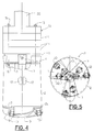
- reference numeral 1 indicates generally a drilling tool according to the invention, designed to drill rock for ventilating shafts and large diameter piles construction.
- the drilling tool 1 is mounted to the lowermost of a telescopic rod string 20 of a drilling rig 30.
- the kind of rig of which an example is given in the drawings, is not to be considered limiting, as any kind of a rig that is suitable for use with a drilling tool of the invention can be used.
- the rods 20 are rotated by a conventional rotary head 22.
- the rotary head 22 is vertically movable along a drilling tower 21 which is transported by an articulated quadrilateral linkage 24, a crawler tracked tractor 23.
- the tool 1 of the invention consists of a thin wall metal container 2 substantially cylindrical or truncated-cone in shape.
- the container 2 is upwardly tapered and welded at the top to an upper plate 3 which is fixedly connected to a standard socket 4 for attaching to the telescopic rods 20 (shown in FIG. 4) connecting to the rotary head 22 (shown on FIG. 7).
- a tubular member 5 is disposed coaxially in the centre of the container 2.
- Tubular member 5 is slightly longer than the container 2 and has its bottom end portion welded to a circular plate 6 (FIG. 3), whilst its upper end portion is welded to the socket 4.
- the bottom circular plate 6 is securely fixed to the lower edge 2a of the truncated-cone container 2 by means of three radial plates or blades 7 disposed at equal angles around the vertical axis.
- the radial plates 7 are slightly inclined downwardly and towards the central axis, as the circular plate 6 is somewhat below the edge 2a.
- the three radial plates 7 and the edge 2a of the container determine three apertures 8 through which the crushed rock is conveyed to the inside of the container 2, as will appear more clearly hereinafter.
- the drilling tool 1 With the aim of facilitating crushed rock penetration into the container 2, the drilling tool 1 is fitted with three lower helical curved blades 9. Each blade 9 is welded to one of the two radial edges of radial plates 7 adjacent to the apertures 8. The concavities of the blades 9 are facing the direction of rotation of the drilling tool 1, counter-clockwise according to FIG. 2.
- cutters 10 are mounted to plate 6 and radial plates 7.
- the cutters 10 are of the rotating disk kind currently used with drilling machines for tunnelling, and may vary in number, kind (with one or two cutting disks, as shown in FIGS. 4 and 5), and diameter, as a function of the bore or pile diameter to be drilled.
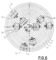
- the cutters are disposed so that their paths will uniformly cover the entire drilling section.
- the cutters are arranged so as to get the centre of thrust to coincide with the vertical axis of the drilling tool.
- FIG. 6 shows the cutting paths 11 of the cutting members 12 of the cutters 10. As shown, the paths 11 are distributed uniformly on the entire section.
- the spacing between two adjacent paths represents the cutting pitch and therefore the size according to which the rock is chipped and crushed.
- Rock fracturing occurs by interaction of the rotating disks and the adjacent cuttings similarly to full section drilling machines for tunnelling. Further, the cutters are distributed on the inclined plates 7 so as to provide maximum steadiness when the drilling tool rotates about its axis, and maintain the drilled bore vertical.
- a predetermined load 13 bearing on the plate 2 must be provided.
- the load 13 is composed by a plurality of stacked modular elements 14 in which bores are obtained for inserting bolts 15 that securely fasten the elements 14 to the plate 2 by means of nuts 16.
- a central bore (not shown) is obtained in each element 14 forming the load 13 for inserting same on the rod 20 connected to socket 4.
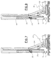
- the number of elements 14 is chosen so as to form a load having a weight capable of providing the cutters with the required thrust. However, said number must be consistent with the lifting power of the on-surface rig 30 (FIGS. 7 and 8) on which the drilling tool is mounted.
- the rock spalls being crushed by the cutters are loaded inside the hollow container 2 by means of the curved blades 9 where the are tamped due to the truncated-cone shape of the container.
- the rock spalls can be eliminated cyclically when the container is full and the tool is withdrawn, by supplying pressurized water through inlet apertures 17 obtained diametrically in the container 2.
- the inclined plate assembly 7 can be fitted with a hinge located on one of the outer sides of one of said plates so as to be tilted and open the bottom of the container 2, similarly to soil excavation buckets of known kind.
- an additional load 18 may be fitted.
- the additional load 18 is designed to be assembled in partial elements around the telescopic rods 20 for supporting the drilling tool 1.
- An auxiliary carrying cable 19 is used to lower the additional load 18 down onto the load 13 at the bottom of the rod.
- the carrying cable 19 is usually provided on every kind of drilling rig for constructing drilled piles, and is actuated by a separate winch independent of the winch for driving the assembly formed by the telescopic rods, the load 13 and the drilling tool.
- the present invention allows to increase at will the weight acting on the cutters by adding removable loads of a weight adapted for penetrating rocks having a resistance over 2500 kg/cm2 and for piles having a diameter up to 2500 mm without compromising the steadiness of the on-surface rig.
Landscapes
- Engineering & Computer Science (AREA)
- Life Sciences & Earth Sciences (AREA)
- Geology (AREA)
- Mining & Mineral Resources (AREA)
- Physics & Mathematics (AREA)
- Environmental & Geological Engineering (AREA)
- Fluid Mechanics (AREA)
- General Life Sciences & Earth Sciences (AREA)
- Geochemistry & Mineralogy (AREA)
- Mechanical Engineering (AREA)
- Earth Drilling (AREA)
Applications Claiming Priority (2)
| Application Number | Priority Date | Filing Date | Title |
|---|---|---|---|
| ITTO930417 | 1993-06-09 | ||
| ITTO930417A IT1270436B (it) | 1993-06-09 | 1993-06-09 | Utensile di perforazione per la realizzazione di pali a grande diametro in roccia, pozzi di ventilazione ed altre opere di scavo simili |
Publications (2)
| Publication Number | Publication Date |
|---|---|
| EP0628700A2 true EP0628700A2 (fr) | 1994-12-14 |
| EP0628700A3 EP0628700A3 (fr) | 1995-07-19 |
Family
ID=11411547
Family Applications (1)
| Application Number | Title | Priority Date | Filing Date |
|---|---|---|---|
| EP94108613A Withdrawn EP0628700A3 (fr) | 1993-06-09 | 1994-06-06 | Outil de forage pour la contruction de puits de grand diamètre. |
Country Status (4)
| Country | Link |
|---|---|
| US (1) | US5431238A (fr) |
| EP (1) | EP0628700A3 (fr) |
| JP (1) | JPH07139279A (fr) |
| IT (1) | IT1270436B (fr) |
Cited By (5)
| Publication number | Priority date | Publication date | Assignee | Title |
|---|---|---|---|---|
| US6655474B1 (en) * | 1999-03-11 | 2003-12-02 | I.M.T. S.P.A. | Drill for making wide diameter and high depth holes and method for carrying out said holes |
| CN102704858A (zh) * | 2012-06-18 | 2012-10-03 | 中铁三局集团有限公司 | 一种具有捞石功能的钻孔桩施工用钻具 |
| CN103382827A (zh) * | 2013-07-01 | 2013-11-06 | 北京市三一重机有限公司 | 钻斗和旋挖钻机 |
| EP2740882A1 (fr) * | 2012-12-04 | 2014-06-11 | Bauer Spezialtiefbau GmbH | Dispositif de forage et procédé de création d'un trou de forage |
| CN114233228A (zh) * | 2021-11-11 | 2022-03-25 | 中建八局西南建设工程有限公司 | 一种大直径桩基施工用沉渣处理装置 |
Families Citing this family (4)
| Publication number | Priority date | Publication date | Assignee | Title |
|---|---|---|---|---|
| EP1498576B1 (fr) * | 2002-04-25 | 2007-12-26 | Hitachi Construction Machinery Co., Ltd. | Dispositif de forage pour beche-tariere |
| EP2696027B1 (fr) * | 2012-08-06 | 2016-06-15 | BAUER Spezialtiefbau GmbH | Seau de forage et procédé de forage d'un trou de forage |
| CN107165581A (zh) * | 2017-06-09 | 2017-09-15 | 上海建工二建集团有限公司 | 一种gps钻机钻头及gps钻机桩基成孔施工方法 |
| CN110359465A (zh) * | 2019-07-03 | 2019-10-22 | 深圳市工勘岩土集团有限公司 | 基坑支护咬合桩综合施工方法 |
Family Cites Families (10)
| Publication number | Priority date | Publication date | Assignee | Title |
|---|---|---|---|---|
| US2245750A (en) * | 1938-11-25 | 1941-06-17 | John R Betts | Well boring bucket and method of boring wells |
| US2728553A (en) * | 1954-09-27 | 1955-12-27 | Edwards John | Apparatus for collecting drilling samples |
| DE1186436B (de) * | 1961-04-27 | 1965-02-04 | Josef Wohlmeyer Dipl Ing | Verfahren und Vorrichtung zum Bohren von Stollen, Tunnels, Schaechten, Kanaelen od. dgl. |
| DE1186428B (de) * | 1963-11-30 | 1965-02-04 | Salzgitter Maschinen Ag | Bohrschappe fuer Trockenbohrungen, insbesondere in zaehem Erdreich |
| US3648788A (en) * | 1970-07-06 | 1972-03-14 | Mckinney Drilling Co | Drilling apparatus |
| US4330155A (en) * | 1980-03-26 | 1982-05-18 | Santa Fe International Corporation | Bore hole mining |
| SU1067189A1 (ru) * | 1982-10-15 | 1984-01-15 | Институт Строительства И Архитектуры Госстроя Бсср | Устройство дл бурени скважин |
| SU1079815A1 (ru) * | 1982-11-01 | 1984-03-15 | Институт Строительства И Архитектуры Госстроя | Ковшовый бур |
| CA2007070C (fr) * | 1990-01-03 | 1996-01-23 | Kirk Mcbride Sinclair | Systeme de forage a sec, a air comprime et a corps vertical pour roche dure |
| US5325932A (en) * | 1992-03-27 | 1994-07-05 | The Robbins Company | Down reaming apparatus |
-
1993
- 1993-06-09 IT ITTO930417A patent/IT1270436B/it active IP Right Grant
-
1994
- 1994-06-06 EP EP94108613A patent/EP0628700A3/fr not_active Withdrawn
- 1994-06-08 JP JP6126580A patent/JPH07139279A/ja not_active Withdrawn
- 1994-06-08 US US08/254,635 patent/US5431238A/en not_active Expired - Fee Related
Cited By (8)
| Publication number | Priority date | Publication date | Assignee | Title |
|---|---|---|---|---|
| US6655474B1 (en) * | 1999-03-11 | 2003-12-02 | I.M.T. S.P.A. | Drill for making wide diameter and high depth holes and method for carrying out said holes |
| CN102704858A (zh) * | 2012-06-18 | 2012-10-03 | 中铁三局集团有限公司 | 一种具有捞石功能的钻孔桩施工用钻具 |
| CN102704858B (zh) * | 2012-06-18 | 2015-12-23 | 中铁三局集团有限公司 | 一种具有捞石功能的钻孔桩施工用钻具 |
| EP2740882A1 (fr) * | 2012-12-04 | 2014-06-11 | Bauer Spezialtiefbau GmbH | Dispositif de forage et procédé de création d'un trou de forage |
| US9376880B2 (en) | 2012-12-04 | 2016-06-28 | Bauer Maschinen Gmbh | Drilling device and method for producing a borehole |
| CN103382827A (zh) * | 2013-07-01 | 2013-11-06 | 北京市三一重机有限公司 | 钻斗和旋挖钻机 |
| CN114233228A (zh) * | 2021-11-11 | 2022-03-25 | 中建八局西南建设工程有限公司 | 一种大直径桩基施工用沉渣处理装置 |
| CN114233228B (zh) * | 2021-11-11 | 2023-12-22 | 中建八局西南建设工程有限公司 | 一种大直径桩基施工用沉渣处理装置 |
Also Published As
| Publication number | Publication date |
|---|---|
| JPH07139279A (ja) | 1995-05-30 |
| ITTO930417A1 (it) | 1994-12-09 |
| EP0628700A3 (fr) | 1995-07-19 |
| ITTO930417A0 (it) | 1993-06-09 |
| IT1270436B (it) | 1997-05-05 |
| US5431238A (en) | 1995-07-11 |
Similar Documents
| Publication | Publication Date | Title |
|---|---|---|
| US5219246A (en) | Drills for piles and soil stabilization, and drilling method | |
| US5417292A (en) | Large diameter rock drill | |
| JP2020070687A (ja) | 鋼管杭の施工方法 | |
| US5431238A (en) | Drilling tool for use in constructing large diameter piles, ventilating shafts and other similar mining works | |
| US5823276A (en) | Diamond-tipped core barrel and method of using same | |
| US6129163A (en) | Flightless rock auger with quick attachment and method of use | |
| JP2021165468A (ja) | 鋼管杭の施工方法 | |
| JP6875707B2 (ja) | 掘削機およびそれを用いた掘削方法 | |
| US20040173383A1 (en) | Apparatus and method for rotary bored drilling | |
| JPH0137558B2 (fr) | ||
| CN212614488U (zh) | 涉及深层混凝土块、碎石层的专用旋挖钻孔设备 | |
| US5366029A (en) | Large shaft over-reamer apparatus and method | |
| CN115341855B (zh) | 一种用于旋挖桩机施工的钻头及其施工方法 | |
| CN112377093A (zh) | 涉及深层混凝土块、碎石层的旋挖钻孔施工方法及专用旋挖钻孔设备 | |
| KR0145495B1 (ko) | 멀티해머오가머신과 싱글해머오가머신을 복합한 지반굴착 방법과 그 장치 | |
| CN216788299U (zh) | 跟进扩孔钻头和旋挖机 | |
| AU2008100106A4 (en) | Drills for piles | |
| JP4642367B2 (ja) | 岩盤の深礎掘削機及びそれを用いた深礎工法 | |
| EP3938615B1 (fr) | Unité de concassage de roche pour élargir un trou pilote réalisé sur un terrain rocheux | |
| CN100441828C (zh) | 一种桩孔施工方法 | |
| JP2715275B2 (ja) | 掘削工法 | |
| EP0990765A1 (fr) | Tube carottier à percussion | |
| CN108425629B (zh) | 地面处理工具和用于在地面中形成钻孔的方法 | |
| KR102078797B1 (ko) | 교각기초 구축을 위한 수중 지반 굴착장치 | |
| GB2270329A (en) | Forming a hole in the ground |
Legal Events
| Date | Code | Title | Description |
|---|---|---|---|
| PUAI | Public reference made under article 153(3) epc to a published international application that has entered the european phase |
Free format text: ORIGINAL CODE: 0009012 |
|
| AK | Designated contracting states |
Kind code of ref document: A2 Designated state(s): AT CH DE ES FR GB IT LI PT SE |
|
| PUAL | Search report despatched |
Free format text: ORIGINAL CODE: 0009013 |
|
| AK | Designated contracting states |
Kind code of ref document: A3 Designated state(s): AT CH DE ES FR GB IT LI PT SE |
|
| 17P | Request for examination filed |
Effective date: 19960117 |
|
| 17Q | First examination report despatched |
Effective date: 19990128 |
|
| STAA | Information on the status of an ep patent application or granted ep patent |
Free format text: STATUS: THE APPLICATION IS DEEMED TO BE WITHDRAWN |
|
| 18D | Application deemed to be withdrawn |
Effective date: 19990608 |