EP0628724A1 - Saugrohrmontage - Google Patents
Saugrohrmontage Download PDFInfo
- Publication number
- EP0628724A1 EP0628724A1 EP94302437A EP94302437A EP0628724A1 EP 0628724 A1 EP0628724 A1 EP 0628724A1 EP 94302437 A EP94302437 A EP 94302437A EP 94302437 A EP94302437 A EP 94302437A EP 0628724 A1 EP0628724 A1 EP 0628724A1
- Authority
- EP
- European Patent Office
- Prior art keywords
- suction conduit
- suction
- retaining tabs
- compressor
- conduit assembly
- Prior art date
- Legal status (The legal status is an assumption and is not a legal conclusion. Google has not performed a legal analysis and makes no representation as to the accuracy of the status listed.)
- Withdrawn
Links
Images



Classifications
-
- F—MECHANICAL ENGINEERING; LIGHTING; HEATING; WEAPONS; BLASTING
- F16—ENGINEERING ELEMENTS AND UNITS; GENERAL MEASURES FOR PRODUCING AND MAINTAINING EFFECTIVE FUNCTIONING OF MACHINES OR INSTALLATIONS; THERMAL INSULATION IN GENERAL
- F16L—PIPES; JOINTS OR FITTINGS FOR PIPES; SUPPORTS FOR PIPES, CABLES OR PROTECTIVE TUBING; MEANS FOR THERMAL INSULATION IN GENERAL
- F16L55/00—Devices or appurtenances for use in, or in connection with, pipes or pipe systems
- F16L55/02—Energy absorbers; Noise absorbers
- F16L55/033—Noise absorbers
-
- F—MECHANICAL ENGINEERING; LIGHTING; HEATING; WEAPONS; BLASTING
- F04—POSITIVE - DISPLACEMENT MACHINES FOR LIQUIDS; PUMPS FOR LIQUIDS OR ELASTIC FLUIDS
- F04B—POSITIVE-DISPLACEMENT MACHINES FOR LIQUIDS; PUMPS
- F04B39/00—Component parts, details, or accessories, of pumps or pumping systems specially adapted for elastic fluids, not otherwise provided for in, or of interest apart from, groups F04B25/00 - F04B37/00
- F04B39/12—Casings; Cylinders; Cylinder heads; Fluid connections
- F04B39/123—Fluid connections
-
- Y—GENERAL TAGGING OF NEW TECHNOLOGICAL DEVELOPMENTS; GENERAL TAGGING OF CROSS-SECTIONAL TECHNOLOGIES SPANNING OVER SEVERAL SECTIONS OF THE IPC; TECHNICAL SUBJECTS COVERED BY FORMER USPC CROSS-REFERENCE ART COLLECTIONS [XRACs] AND DIGESTS
- Y10—TECHNICAL SUBJECTS COVERED BY FORMER USPC
- Y10S—TECHNICAL SUBJECTS COVERED BY FORMER USPC CROSS-REFERENCE ART COLLECTIONS [XRACs] AND DIGESTS
- Y10S181/00—Acoustics
- Y10S181/403—Refrigerator compresssor muffler
Definitions
- the present invention relates generally to refrigerant compressors. More particularly, the present invention relates to refrigerant compressors of the reciprocating piston type which employ a suction gas muffler for attenuating noise resulting from the operation of the compressor.
- the present invention provides a refrigerant compressor having an improved suction gas muffler which effectively attenuates noise generated from the above-mentioned sources while still enabling relatively free unrestricted flow to the compressor.
- the suction gas muffler of the present invention is of the side branch type and comprises a relatively large diameter conduit having a housing secured thereto which defines a pair of side branch chambers each of which may be tuned to a different fundamental frequency.
- a pair of longitudinally spaced openings provide communication with each of the respective chambers and serves to define an impedance tube therebetween which may be tuned to attenuate a third fundamental frequency.
- Integrally formed baffles and ribs within each of the chambers further aid in noise attenuation by eliminating standing waves within the chambers as well as enhancing the rigidity of the muffler.
- the muffler is preferably fabricated from a polymeric composition so as to minimize heating of the suction gas being supplied to the compressor. Further, the use of such polymeric materials enables the suction conduit and muffler to be very inexpensively fabricated by suitable forming means such as, for example, injection molding.
- the suction muffler is mounted to the motor cover using a twist lock design which incorporates a novel formed-in ring which creates a lip seal between the motor cover and the suction muffler.
- This integral sealing ring eliminates the need and associated costs of having an O-ring and snap-on sleeve mounting system common to assignee's prior art design as shown in assignee's U.S. Letters Patent 5,129,793.
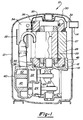
- Refrigeration compressor 10 includes an outer shell 12 having a suction inlet 14 and a motor compressor assembly 16 resiliently mounted therein.
- Motor compressor 16 includes a compressor housing 18 having a crankshaft 20 rotatably journaled therein and operative to reciprocate pistons 22 and 24 within respective cylinders 25, 26.
- a motor assembly 27 includes a stator 28 having a lower end secured to compressor housing 18 and a rotor 29 secured to crankshaft 20 so as to rotatably drive same.
- a motor cover 30 is secured to and encloses the upper end of stator 28 and includes an outwardly flared suction inlet opening 32 positioned in spaced aligned facing relationship to suction inlet 14.
- a suction conduit assembly 34 shown in Figure 3, including a suction muffler portion 35 is also provided having one end fitted within an opening 36 provided in the sidewall of motor cover 30, the other end extending downwardly and fitted within an opening 38 provided in head 40 whereby suction gas is supplied to respective cylinders 25, 26 via suction chamber 42 and compressed gas is discharged therefrom into discharge chamber 43.
- a bypass conduit 44 is also provided having one end fitted within an opening 46 provided in annular flange portion 48 of compressor housing 18.
- the other end of bypass conduit 44 extends upwardly alongside of suction muffler 34 and is fitted within an opening 50 provided in the sidewall of upper conduit portion 52 of suction conduit assembly 34.
- both suction conduit assembly 34 and bypass conduit 44 will be fabricated from a material having a relatively low coefficient of heat transfer such as polymeric composition so as to minimize the heating of the suction gas flowing to the compressor.
- FIG. 4 shows the attachment and sealing arrangement utilized between the prior art suction mufflers and motor cover 30.
- Upper end 52 of system conduit assembly 34 is provided with an annular collar 200.
- annular flange 202 Located axially outward from annular collar 200 is an annular flange 202 and extending axially outward from annular flange 202 is an annular section 204. Extending radially outward from the open end of annular section 204 are a plurality of retaining tabs 206.
- the outside diameter of annular flange 202 is sized to receive an O-ring 208 for sealing the connection to opening 36 in motor cover 30.
- a snap-on sleeve 210 is provided which has an inside diameter 212 designed to fit over annular flange 202 and an outer sleeve 214 which fits over annular collar 200.
- a radially inwardly projecting tab 216 snaps over annular collar 200 to retain sleeve 210 with O-ring 208 being placed in a slightly compressed condition to effect a seal between annular collar 200 and sleeve 210.
- the width of outer sleeve 214 is selected such that when tab 216 is snapped over collar 200, O-ring 208 is placed in slight compression between sleeve 210 and collar 200.
- the gap 218 between sleeve 210 and the plurality of retaining tabs 206 is less than the thickness of the material forming motor cover 30.
- the plurality of retaining tabs 206 are aligned with a plurality of corresponding slots (not shown) in motor cover 30.
- Suction conduit assembly 34 is then pushed towards motor cover 30 until retaining tabs 206 extend beyond the inside surface of motor cover 30.
- Suction conduit assembly 34 is then rotated into position with motor cover 30 being sandwiched between retaining tabs 206 and sleeve 210 to retain suction conduit assembly 34 onto motor cover 30.
- This assembly of suction conduit assembly 34 onto motor cover 30 causes further compression of O-ring 208 due to gap 218 initially being smaller than the thickness of the material forming motor cover 30.
- the force exerted by the compressed O-ring 208 creates a seal between snap-on sleeve 210 and motor cover 30 and also acts to eliminate any type of noise or rattling caused by the movement between suction conduit assembly 34 and motor cover 30.
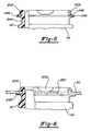
- FIGS 5 and 6 show the attachment and sealing arrangement according to the present invention.
- Upper end 52 of suction conduit assembly 34 is provided with an annular section 244 extending therefrom. Extending radially outward from the open end of annular section 244 are the plurality of retaining tabs 206 similar to those shown in Figure 4.
- An integral annular sealing ring 246 extends radially outward from annular section 244 and is located between the plurality of retaining tabs 206 and upper end 52 of suction conduit assembly 34.
- Annular ring 246 is angled slightly towards the open end of suction conduit assembly 34 as can best be seen in Figure 5, the unassembled illustration. In the preferred embodiment, annular ring 246 is angled approximately 14° towards the open end of suction conduit assembly 34.
- Annular sealing ring 246 is positioned on annular section 244 such that the gap 248 between the tip of annular sealing ring 246 and the plurality of retaining tabs 206 is less than the thickness of the material forming motor cover 30.
- the plurality of retaining tabs 206 are aligned with a plurality of corresponding slots 250 in motor cover 30.
- Suction conduit assembly 34 is then pushed towards motor cover 30 until retaining tabs 206 extend beyond the inside surface of motor cover 30.
- Suction conduit assembly 34 is then rotated into position with motor cover 30 being sandwiched between retaining tabs 206 and annular ring 246 to retain suction conduit assembly 34 onto motor cover 30 as shown in Figure 6.
- This assembly of suction conduit assembly 34 onto motor cover 30 causes elastic deformation of annular ring 246 due to gap 248 initially being smaller than the thickness of the material forming motor cover 30.
- the force exerted by the elastic deformation of annular ring 246 creates a lip type seal between annular ring 246 and motor cover 30 and also acts to eliminate any type of noise or rattling caused by the movement between suction conduit assembly 34 and motor cover 30.
- annular ring 246 to the upper end 52 of suction conduit assembly 34 eliminates the need for the additional components of the prior art including O-ring 208 and sleeve 210 along with their associated costs, complexities and assembly requirements.
- Suction conduit 134 is similar to suction conduit 34 with the exception of suction muffler portion 35, which has been eliminated.
- the internal and external diameters of suction conduit 134 are increased in diameter at 61. This increase in diameter provides a step 63 on the internal diameter of suction conduit 134 which is operative to reflect pressure waves coming from the compressor cylinder inlet.
- the increase in diameter serves to reduce the suction work required of the compressor which thus improves the efficiency of the compressor.
- suction conduit 134 This stepped design of suction conduit is described more fully in assignee's copending Patent Application Number 49,985 filed April 16, 1993 and entitled “Suction Gas Conduit", the disclosure of which is hereby incorporated herein by reference.
- the remaining details of suction conduit 134 are similar to suction conduit 34 including opening 50 provided in the sidewall of upper conduit portion 52. Suction conduit 134 thus provides an unrestricted suction gas flow to compressor 10.
Landscapes
- Engineering & Computer Science (AREA)
- General Engineering & Computer Science (AREA)
- Mechanical Engineering (AREA)
- Compressor (AREA)
Applications Claiming Priority (2)
| Application Number | Priority Date | Filing Date | Title |
|---|---|---|---|
| US68791 | 1979-08-22 | ||
| US08/068,791 US5330329A (en) | 1993-06-01 | 1993-06-01 | Suction conduit assembly mounting |
Publications (1)
| Publication Number | Publication Date |
|---|---|
| EP0628724A1 true EP0628724A1 (de) | 1994-12-14 |
Family
ID=22084737
Family Applications (1)
| Application Number | Title | Priority Date | Filing Date |
|---|---|---|---|
| EP94302437A Withdrawn EP0628724A1 (de) | 1993-06-01 | 1994-04-06 | Saugrohrmontage |
Country Status (3)
| Country | Link |
|---|---|
| US (1) | US5330329A (de) |
| EP (1) | EP0628724A1 (de) |
| CN (1) | CN1099123A (de) |
Families Citing this family (10)
| Publication number | Priority date | Publication date | Assignee | Title |
|---|---|---|---|---|
| CN1078931C (zh) * | 1995-03-30 | 2002-02-06 | Lg电子株式会社 | 安装密闭式压缩机的消声器的装置 |
| CN1091844C (zh) * | 1995-04-28 | 2002-10-02 | Lg电子株式会社 | 用于装配密封式压缩机的吸气噪音消声器的装置 |
| FR2737766B1 (fr) * | 1995-08-11 | 1997-09-19 | Soc Et Et De Realisations Ind | Dispositif pour la fixation rigide et etanche de deux conduits |
| DE10128225C1 (de) * | 2001-06-11 | 2002-12-05 | Danfoss Compressors Gmbh | Saugschalldämpfer |
| US20040234386A1 (en) * | 2003-05-19 | 2004-11-25 | Chumley Eugene Karl | Discharge muffler having an internal pressure relief valve |
| US6935848B2 (en) * | 2003-05-19 | 2005-08-30 | Bristol Compressors, Inc. | Discharge muffler placement in a compressor |
| DE102006011577A1 (de) * | 2006-03-10 | 2007-09-13 | Linde Ag | Verdichteranlage mit einem Pufferbehälter |
| DE102009049988A1 (de) * | 2009-10-20 | 2011-04-21 | Linde Ag | Verdichteranlage |
| US20150300337A1 (en) * | 2011-12-23 | 2015-10-22 | Gea Bock Gmbh | Compressor |
| WO2014017051A1 (ja) * | 2012-07-25 | 2014-01-30 | パナソニック株式会社 | 密閉型圧縮機及びそれを備える冷凍装置 |
Citations (2)
| Publication number | Priority date | Publication date | Assignee | Title |
|---|---|---|---|---|
| DE9003005U1 (de) * | 1990-03-12 | 1990-05-17 | Rowenta-Werke Gmbh, 6050 Offenbach | Elektrischer Staubsauger |
| US5129793A (en) * | 1990-10-24 | 1992-07-14 | Copeland Corporation | Suction muffler |
Family Cites Families (11)
| Publication number | Priority date | Publication date | Assignee | Title |
|---|---|---|---|---|
| US3864064A (en) * | 1973-03-12 | 1975-02-04 | Sundstrand Corp | Suction muffler tube for compressor |
| US4412791A (en) * | 1977-02-10 | 1983-11-01 | Copeland Corporation | Refrigeration compressor apparatus and method of assembly |
| US4239461A (en) * | 1978-11-06 | 1980-12-16 | Copeland Corporation | Compressor induction system |
| US4370104A (en) * | 1980-07-22 | 1983-01-25 | White Consolidated Industries, Inc. | Suction muffler for refrigeration compressor |
| US4401418B1 (en) * | 1981-04-29 | 1998-01-06 | White Consolidated Ind Inc | Muffler system for refrigeration compressor |
| US4477229A (en) * | 1982-08-25 | 1984-10-16 | Carrier Corporation | Compressor assembly and method of attaching a suction muffler thereto |
| IT1172782B (it) * | 1983-12-12 | 1987-06-18 | Necchi Spa | Silenziatore per motocompressori |
| BR8804677A (pt) * | 1988-09-06 | 1990-06-05 | Brasil Compressores Sa | Sistema de succao direta para compressor hermetico rotativo e seu processo de montagem |
| US4969804A (en) * | 1989-03-08 | 1990-11-13 | Tecumseh Products Company | Suction line connector for hermetic compressor |
| US5015155A (en) * | 1990-03-26 | 1991-05-14 | Copeland Corporation | Motor cover assembly and method |
| US5205719A (en) * | 1992-01-13 | 1993-04-27 | Copeland Corporation | Refrigerant compressor discharge muffler |
-
1993
- 1993-06-01 US US08/068,791 patent/US5330329A/en not_active Expired - Lifetime
-
1994
- 1994-04-06 EP EP94302437A patent/EP0628724A1/de not_active Withdrawn
- 1994-04-25 CN CN94104640.0A patent/CN1099123A/zh active Pending
Patent Citations (2)
| Publication number | Priority date | Publication date | Assignee | Title |
|---|---|---|---|---|
| DE9003005U1 (de) * | 1990-03-12 | 1990-05-17 | Rowenta-Werke Gmbh, 6050 Offenbach | Elektrischer Staubsauger |
| US5129793A (en) * | 1990-10-24 | 1992-07-14 | Copeland Corporation | Suction muffler |
Also Published As
| Publication number | Publication date |
|---|---|
| US5330329A (en) | 1994-07-19 |
| CN1099123A (zh) | 1995-02-22 |
Similar Documents
| Publication | Publication Date | Title |
|---|---|---|
| US4239461A (en) | Compressor induction system | |
| EP1304480B1 (de) | Silencieux d'aspiration pour compresseur | |
| EP1756431B1 (de) | Mit einem kompressorgehäuse verbundener schalldämpfer | |
| US4370104A (en) | Suction muffler for refrigeration compressor | |
| EP0551713B1 (de) | Auspuffschalldämpfer für einen Kühlverdichter | |
| CN107762801B (zh) | 压缩机 | |
| KR200146151Y1 (ko) | 압축기의 소음감쇄기 | |
| US5330329A (en) | Suction conduit assembly mounting | |
| US6206135B1 (en) | Suction noise muffler for hermetic compressor | |
| CN101240762B (zh) | 具有带内部噪声衰减调谐的弹性联接件的发动机进气系统 | |
| US5129793A (en) | Suction muffler | |
| KR100252593B1 (ko) | 냉동 압축기(A refrigeration compressor) | |
| KR101236635B1 (ko) | 맥동 감쇠 챔버를 포함하는 내연기관용 터보차저 장치 | |
| US6176688B1 (en) | Discharge muffler arrangement | |
| CN110985341A (zh) | 消音器、压缩机和家用电器 | |
| JP5917546B2 (ja) | リニアモータ圧縮機の吸入マフラの実装構成 | |
| CN100366869C (zh) | 排气消声器 | |
| US20230167825A1 (en) | A scroll compressor provided with a discharge muffler arrangement | |
| KR101855047B1 (ko) | 왕복동식 압축기 | |
| EP0614009B1 (de) | Vakuumpumpe | |
| CN213511103U (zh) | 线性压缩机 | |
| US20040234386A1 (en) | Discharge muffler having an internal pressure relief valve | |
| KR101891928B1 (ko) | 압축기용 머플러 | |
| US20060002807A1 (en) | Hermetic compressor | |
| KR100314013B1 (ko) | 리니어 압축기의 흡입소음기 구조 |
Legal Events
| Date | Code | Title | Description |
|---|---|---|---|
| PUAI | Public reference made under article 153(3) epc to a published international application that has entered the european phase |
Free format text: ORIGINAL CODE: 0009012 |
|
| AK | Designated contracting states |
Kind code of ref document: A1 Designated state(s): ES FR IT |
|
| STAA | Information on the status of an ep patent application or granted ep patent |
Free format text: STATUS: THE APPLICATION IS DEEMED TO BE WITHDRAWN |
|
| 18D | Application deemed to be withdrawn |
Effective date: 19950615 |