EP0628726A2 - Flügelzellenpumpe mit veränderlicher Fördermenge - Google Patents
Flügelzellenpumpe mit veränderlicher Fördermenge Download PDFInfo
- Publication number
- EP0628726A2 EP0628726A2 EP94108581A EP94108581A EP0628726A2 EP 0628726 A2 EP0628726 A2 EP 0628726A2 EP 94108581 A EP94108581 A EP 94108581A EP 94108581 A EP94108581 A EP 94108581A EP 0628726 A2 EP0628726 A2 EP 0628726A2
- Authority
- EP
- European Patent Office
- Prior art keywords
- primary
- intermediate casing
- governor
- annulus
- pump
- Prior art date
- Legal status (The legal status is an assumption and is not a legal conclusion. Google has not performed a legal analysis and makes no representation as to the accuracy of the status listed.)
- Ceased
Links
- 239000000446 fuel Substances 0.000 claims abstract description 30
- 238000005086 pumping Methods 0.000 claims abstract description 24
- 239000007788 liquid Substances 0.000 claims description 64
- 238000006073 displacement reaction Methods 0.000 claims description 15
- 230000004044 response Effects 0.000 claims description 3
- 239000012530 fluid Substances 0.000 abstract description 6
- 230000008859 change Effects 0.000 description 3
- 230000007423 decrease Effects 0.000 description 3
- 230000003247 decreasing effect Effects 0.000 description 3
- 230000004048 modification Effects 0.000 description 3
- 238000012986 modification Methods 0.000 description 3
- 238000010276 construction Methods 0.000 description 2
- 230000007246 mechanism Effects 0.000 description 2
- OKTJSMMVPCPJKN-UHFFFAOYSA-N Carbon Chemical compound [C] OKTJSMMVPCPJKN-UHFFFAOYSA-N 0.000 description 1
- 230000009286 beneficial effect Effects 0.000 description 1
- 229910052799 carbon Inorganic materials 0.000 description 1
- 230000006835 compression Effects 0.000 description 1
- 238000007906 compression Methods 0.000 description 1
- 238000005516 engineering process Methods 0.000 description 1
- 238000003780 insertion Methods 0.000 description 1
- 230000037431 insertion Effects 0.000 description 1
- 238000000034 method Methods 0.000 description 1
- 230000008520 organization Effects 0.000 description 1
- 230000001105 regulatory effect Effects 0.000 description 1
- 238000001228 spectrum Methods 0.000 description 1
- 238000010408 sweeping Methods 0.000 description 1
Images


Classifications
-
- F—MECHANICAL ENGINEERING; LIGHTING; HEATING; WEAPONS; BLASTING
- F04—POSITIVE - DISPLACEMENT MACHINES FOR LIQUIDS; PUMPS FOR LIQUIDS OR ELASTIC FLUIDS
- F04C—ROTARY-PISTON, OR OSCILLATING-PISTON, POSITIVE-DISPLACEMENT MACHINES FOR LIQUIDS; ROTARY-PISTON, OR OSCILLATING-PISTON, POSITIVE-DISPLACEMENT PUMPS
- F04C14/00—Control of, monitoring of, or safety arrangements for, machines, pumps or pumping installations
- F04C14/10—Control of, monitoring of, or safety arrangements for, machines, pumps or pumping installations characterised by changing the positions of the inlet or outlet openings with respect to the working chamber
Definitions
- This invention relates generally to positive displacement, variable delivery pumping apparatus of the vane pump-type driven by either a constant speed or a varying speed power source and delivering controlled variable flow of a pumped liquid, such as fuel. More particularly, the invention relates to an improved two stage vane pump apparatus for delivering fuel to an aircraft jet engine or gas turbine at a controllable fuel flow rate which is independent of the driven speed of the pump.
- liquid fuel is pumped to a gas turbine, such as a jet aircraft engine, using positive displacement, variable delivery pumping apparatus.
- positive displacement pumps have included gear pumps, vane pumps and piston pumps.
- Variable delivery has been achieved by changing the geometry of the positive displacement pump or by bypassing liquid to the inlet, both of which decrease the overall efficiency and require power as the flow is varied.
- Two stage pumping arrangements for jet engine fuel are also known which are combined with various accessory apparatus to meet the particular requirements of aircraft jet engines, which involve a large number of hydromechanical accessory devices in the overall fuel control system. All of the above add to the cost. It would be desirable to have a simplified positive displacement, variable delivery pumping apparatus which provides for variable flow of the pumped liquid suitable for either constant speed or variable speed drive and without the need to change the geometry of the pump hardware. Furthermore it would be desirable to have an improved variable delivery, positive displacement pumping apparatus which will operate without bypassing flow back to the inlet using simplified controls.
- one object of the present invention is to provide an improved positive displacement, variable delivery pumping apparatus which provides variable flow with simplified controls and more efficiently than existing pumping apparatus.
- Another object of the invention is to provide an improved fuel delivery system for an aircraft jet engine.
- Still another object of the invention is to provide a variable flow pump suitable for constant or variable input drive speed which is efficient and which operates with a simple control system.
- the invention comprises a primary vane pump comprising a primary rotor and an intermediate casing, both of which are rotatably mounted within a fixed housing.
- the casing also has vanes and forms a governor vane pump with the housing.
- a stationary inlet annulus and a stationary discharge annulus both communicate with passages within the rotatable primary vane pump and provide a primary pumped liquid flow path from a source of primary liquid to a user.
- a source of governing liquid is connected to feed the inlet of the governor vane pump, and the governor vane pump outlet is connected to a flow control valve and back to the governing liquid source. Operation of the flow control valve restricts flow of the governing liquid and adjusts speed of the intermediate casing to provide variable delivery from the primary liquid source to user.
- the invention is practiced by providing a positive displacement, variable delivery vane-type pumping apparatus with a primary stage and a governor stage, comprising a primary pump rotor with circumferentially spaced moveable primary stage vanes, a rotatable intermediate casing with a noncircular primary pump cavity receiving the primary stage vanes and adapted to establish diametrically opposed primary suction chambers and diametrically opposed primary pressure chambers between the rotor and the intermediate casing when there is relative rotation therebetween.
- the rotatable intermediate casing further includes circumferentially spaced movable governor stage vanes and is rotatably mounted in a stationary housing which also rotatably mounts the pump rotor.
- the stationary housing includes a noncircular governor pump cavity arranged to receive the governor stage vanes and adapted to establish diametrically opposed governor suction chambers and diametrically opposed governor pressure chambers between the intermediate casing and the stationary housing when the intermediate casing rotates.
- a stationary inlet annulus and a stationary discharge annulus each define a circumferential opening communicating with ports in the rotatable intermediate casing.
- a first pair of passages in the rotatable intermediate casing connects the inlet annulus to the primary suction chambers.
- a second pair of passages in the rotatable intermediate casing connects the primary pressure chamber to the discharge annulus.
- a third pair of passages connects the discharge annulus to the governor suction chambers.
- a fourth conduit including a pair of internal passages is connected between the governor pressure chambers and an external flow control valve, and a fifth conduit connects the flow control valve back to the discharge annulus.
- the governor suction chamber is supplied from the inlet annulus and the flow control valve outlet is connected back to the inlet annulus.
- rotational torque tending to rotate the intermediate casing is provided by pressure difference of the primary liquid between inlet and discharge annulus caused by rotation of the primary rotor and the downstream passage restrictions.
- Counter rotational torque tending to resist rotation of the intermediate casing is provided in the governor stage by regulated pressure drop of the governing liquid across the flow control valve.
- Speed of rotation of the intermediate casing as a result of two opposite rotational torques determines the volumetric flow rate supplied by the primary stage to the engine.
- the primary liquid and the governing liquid are preferably the same liquid and derived from the same source, but not necessarily so.
- a two stage vane-type positive displacement pump indicated generally at 1 and driven by either a constant speed or variable speed motor or engine (not shown) through an input shaft 2.
- the pumping apparatus 1 is made up of a fixed pump housing 3, a primary pump rotor 4, and an intermediate rotatable casing 5 interposed therebetween, best seen in Fig. 3 cross section.
- the pump housing 3 is connected at an inlet opening 6 to a source of pressurized primary liquid, such as jet engine fuel, (not shown) and a controlled supply of pumped primary liquid leaves housing 3 through a discharge connection 7.
- Primary pump rotor 4 is rotatably mounted in the housing 3 by means of roller bearings 8, 9.
- the pump rotor 4 comprises a central cylindrical body 12 having longitudinal circumferentially spaced slots 13, in each of which is disposed a movable primary stage vane 14.
- intermediate casing 5 includes a central cylindrical body 15 having longitudinal circumferentially spaced slots 16, in each of which is disposed a movable governor stage vane 17.
- the intermediate casing 15 has an inner noncircular cavity 18 which receives the ends of the vanes 14 to provide a primary stage vane pump when there is relative rotation between rotor 4 and intermediate casing 5.
- the term relative rotation is used, because in practice both rotor 4 and casing 5 may be rotating and only relative movement between the two creates a pressure difference across the vanes and flow from the primary pump inlet to outlet.
- Housing 3 also has an inner noncircular cavity 19 receiving the ends of vanes 17 to form a governor stage.
- FIG. 5 of the drawing illustrates an enlarged view of the governor stage vanes 17 which are preferably each loaded by a compression spring 20 and include a pressure balancing conduit 21 therethrough. This is to insure that vanes 17 are always extended from slots 16 against the chamber wall 19 even when intermediate casing 5 is not rotating.
- Housing 3 is illustrated in simplified form as comprising an inlet face plate 22 having an inner axially extending boss 22a supporting the stub end of shaft 2 in the needle bearings 8. Attached to the face plate 22 by bolts 23 is a housing inlet sleeve 24, a housing body 25, and housing drive end face plate 26.
- the drive end face plate includes an inner axially extending boss 26a supporting shaft 2 in the needle bearings 9.
- Housing sleeve 24 and housing body 25 are arranged to hold the sleeve bearings 10 and 11 respectively which rotatably support the intermediate casing 5.
- the details of construction of housing 3 are merely exemplary to illustrate a simplified construction and housing 3 may take other forms and shapes to meet the physical needs of a particular pump. As seen in Figs. 2, 3 and 4 the housing includes longitudinal ribs 27 with axial holes 28 receiving the bolts 23.
- the opposite ends of intermediate casing 5 are sealed against fluid leakage across the ends by means of conventional spring loaded carbon face seals 29, 30.
- a stationary inlet annulus 31 In order to provide for a continuous supply of primary liquid from inlet opening 6 to internal passages in the rotatable intermediate casing 5, there is provided a stationary inlet annulus 31. This is suitably provided as a circumferential groove in the end of the boss 22a and connected to inlet 6 by passage 32. Similarly, in order to provide for a continuous egress of primary liquid from rotatable casing 5, there is provided a stationary discharge annulus 33. This is provided by means of a circumferential groove in the housing body 25 and connected to the discharge port 7 by means of a passage 34. A pair of first internal conduits 35 connect inlet annulus 31 to the ends of diametrically opposed primary suction chambers 40 (see Fig. 3).
- a pair of second conduits 36 connect the ends of diametrically opposed primary pressure chambers 41 in the intermediate casing 5 to the discharge annulus 33.
- a pair of third conduits 37 connect discharge annulus 33 to the ends of diametrically opposed governor stage suction chambers 42.
- a pair of fourth conduits 38 lead from diametrically opposed governor pressure chambers 43 to a flow control valve as will be explained later in the specification.
- Intermediate casing 5 is made up of a cylindrical barrel shaped body number 44 with an inner sleeve 45 rotatably connected thereto by one or more radial pins 46. This is to allow insertion and removal of the primary pump rotor during assembly.
- Body 44 includes journals 47, 48 fitting within sleeve bearings 10, 11 respectively.
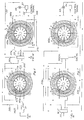
- the primary stage shown on the left hand side has been separated from the governor stage shown on the right hand side in order to facilitate understanding of the flow of the pumped liquid.
- the primary stage is supplied by means of a pair of diametrically opposed primary suction chambers 40a, 40b established in the clearance space of gradually increasing volume (as determined by the direction of rotation of rotor 4 relative to intermediate casing 5).
- a pair of diametrically opposed primary pressure chambers 41a, 41b are established in the clearance space of decreasing volume between rotor 4 and casing 5.
- governor suction chambers 42a, 42b and governor pressure chambers 43a, 43b are established in regions of increasing and decreasing volume respectively.
- a pair of first conduits 35a, 35b connect inlet annulus 31 to primary suction chambers 40a, 40b.
- a pair of second conduits 36a, 36b connect primary pressure chambers to the discharge annulus 33.
- a pair of third conduits 37a, 37b connect the discharge annulus 33 to governor suction chambers 42a, 42b.
- conduits 38a, 38b connect governor pressure chambers 43a, 43b to the inlet of a flow control valve 49.
- the outlet side of flow control valve 49 is reconnected to discharge annulus 33 by means of a conduit 50.
- Flow control valve 49 is provided with a servo positioning mechanism 51 in response to a fuel demand signal 52 representing a desired rate of fuel flow from the pumping apparatus to the engine.
- the conduit 50 connecting the outlet of flow control valve 49 back to the discharge annulus is at substantially the same pressure as that of the discharge annulus and conduits 37a, 37b leading to the suction chambers of the governor stage.
- a primary conduit means is established from inlet annulus to primary pump suction chambers to primary pump pressure chambers to discharge annulus to engine.
- governing liquid which governs the rate of pump delivery.
- the governing liquid is the same liquid as the primary liquid, i.e. the primary fuel supply also operates the governor stage.
- a governor conduit means is established from a governing liquid source, in this case the discharge annulus, to governor suction chambers to governor pressure chambers to flow control valve and back to the governing liquid source (or discharge annulus).
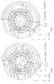
- Fig. 8 of the drawing a diagrammatic representation is made for the purpose of explaining the operation.
- the same reference numerals are used as in connection with Figure 6, except that both stages are drawn together and the stationary inlet annulus and discharge annulus 31 and 33 respectively are shown encircling the apparatus to indicate that they are actually stationary and circumferentially disposed with respect to the rotatable members of the apparatus.
- the first conduits 35a, 35b and the second conduits 36a, 36b are shown with sliding connections to indicate that they actually are rotatable along with the intermediate casing 5 with respect to the stationary annuli.
- Fig. 8 is drawn with conduits shown as single lines of three different thicknesses to indicate that there are different liquid pressure levels within the conduits, the thinner lines indicating lower pressure and the thick lines indicating higher pressure. Three different pressure levels are indicated in Fig. 8, it being assumed that the intermediate casing 5 is rotating at some rotational speed N2 which is less than the rotational speed N1 of the driven primary rotor 4.
- first conduits 35a, 35b and primary suction chambers 40a, 40b are at substantially the same low pressure (disregarding slight pressure drops through the passages).
- Primary pressure chambers 41a, 41b, second conduits 36a, 36b and discharge annulus 33 are at some intermediate pressure which corresponds to the pressure at which fuel is supplied by the primary stage to the engine. Also the discharge annulus acts as a governing liquid source. Therefore, third conduits 37a, 37b connected to governor stage suction chambers 42a, 42b, and conduit 50 from the outlet of flow control valve 49 are also connected to discharge annulus 33, and are therefore approximately at this intermediate pressure.
- conduits 38a, 38b from the governor pressure chambers 43a, 43b are at a higher pressure and are connected to the inlet of flow control valve 49.
- the primary pump stage delivers liquid, in this case jet engine fuel, from the discharge annulus at a volumetric rate of flow determined by the relative rate of rotation between primary rotor 4 rotating at speed N1 and intermediate casing 5 rotating at speed N2.
- the vanes 14 are either sweeping through suction chambers of increasing volume or pressure chambers of decreasing volume.
- the differential pressure thus developed is exerted on the projected areas of the intermediate casing cavity 18, seen in Fig. 8 to exert a clockwise rotational torque on casing 5.
- intermediate casing 5 were mechanically locked in place, as in a conventional vane pump, the liquid fuel would be delivered from the discharge annulus at a volumetric rate of flow proportional to the primary rotor speed N1.
- intermediate casing 5 is rotatably mounted.
- a closed loop flow path is established through a governor conduit means from discharge annulus to the governor stage suction chambers 42a, 42b to the governor pressure chambers 43a, 43b (whenever casing 5 is rotating), through flow control valve 49 and back to the discharge annulus 33. This is best seen in Fig. 6.
- Governing to provide variable deliver of liquid fuel is provided by selectively positioning control valve 49 as exemplified by a servo mechanism 51 controlled by a fuel demand control signal 52. Restriction of flow through the control valve in the closed loop liquid circuit causes a pressure drop across the valve and a corresponding pressure rise between governor suction and pressure chambers. This latter pressure difference provides a counter-rotational torque on intermediate casing 5 which, in turn, causes it to rotate at speed N2 which is less than that of primary rotor N1.
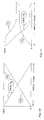
- FIG. 10 illustrates the characteristics of the pumping apparatus when rotor 4 is driven at a constant speed N1.
- the abscissa represents valve opening and the ordinate represents either rotational speed or volumetric flow Q from the discharge annulus.
- control valve 49 As control valve 49 is opened, rotational speed N2 of the intermediate casing 5 increases, and the relative rotational speed N1 minus N2 decreases, as well as the volumetric flow Q.
- FIG. 11 illustrates flow characteristics of the pumping apparatus when the primary rotor 4 is driven by a variable speed motor.
- the speed N1 would vary.
- opening of the flow control valve causes the relative rotational speed N1 minus N2 and the volumetric rate of flow Q to decrease, as indicated in the graph of Fig. 11.
- Figs. 7 and 9 While I have described the preferred form of the invention, a modified form is illustrated in Figs. 7 and 9. In order not to obscure the drawing and to illustrate the differences, only the conduits which are different from those in the corresponding figures 6 and 9, and elements discussed in the following description, have been shown with reference numbers. Since the path through the governor stage and control valve is a continuous closed circuit, it can be obtained from and returned to any convenient source of governing liquid. As seen in Fig. 7, the inlet annulus 31 is utilized rather than the discharge annulus for the source of governing liquid.
- Conduits 53a, 53b are substituted for conduits 37a, 37b shown in Fig. 6.
- the return from the outlet of control valve 49 is shown as a conduit 54 returning to the inlet annulus in lieu of the conduit 50 shown in Fig. 6.
- these changes are indicated in Fig. 9. It will be observed that while some pressure difference is developed across vanes 17 in the governor stage, the pressure level will be lower, since the pressure at the governor suction cavities corresponds to inlet annulus pressure. This lower pressure level may lead to improved geometries for some applications.
- Vane pumps may have any number of lobes from only one lobe, which is most frequently used in variable displacement vane pumps, up to four lobes. I prefer the diametrically opposed chambers shown, but this is not meant to limit the claimed invention.
- the invention provides many advantages over conventional positive displacement, variable delivery pumping apparatus. Because it is unnecessary to change the geometry of he pump to vary the delivery rate, a very efficient fuel delivery system is possible. Secondly, the means of control of fuel delivery is extremely simple, requiring only a flow control valve. Third, the wear on the vanes is reduced, because wear depends upon the sliding velocity of the vanes. Assuming that the pumping apparatus operates with the intermediate casing turning at some speed less than the driven rotor, the vanes of both pump stages are sliding across their respective cavity walls at a lower speed and hence with less wear.
Landscapes
- Engineering & Computer Science (AREA)
- Mechanical Engineering (AREA)
- General Engineering & Computer Science (AREA)
- Details And Applications Of Rotary Liquid Pumps (AREA)
Applications Claiming Priority (2)
| Application Number | Priority Date | Filing Date | Title |
|---|---|---|---|
| US08/073,552 US5378112A (en) | 1993-06-09 | 1993-06-09 | Positive displacement, variable delivery pumping apparatus |
| US73552 | 1993-06-09 |
Publications (2)
| Publication Number | Publication Date |
|---|---|
| EP0628726A2 true EP0628726A2 (de) | 1994-12-14 |
| EP0628726A3 EP0628726A3 (de) | 1995-04-12 |
Family
ID=22114383
Family Applications (1)
| Application Number | Title | Priority Date | Filing Date |
|---|---|---|---|
| EP94108581A Ceased EP0628726A3 (de) | 1993-06-09 | 1994-06-04 | Flügelzellenpumpe mit veränderlicher Fördermenge. |
Country Status (2)
| Country | Link |
|---|---|
| US (1) | US5378112A (de) |
| EP (1) | EP0628726A3 (de) |
Families Citing this family (6)
| Publication number | Priority date | Publication date | Assignee | Title |
|---|---|---|---|---|
| DE19652420A1 (de) * | 1996-12-09 | 1998-06-10 | Luk Fahrzeug Hydraulik | Stromregelanordnung für eine hydraulische Fördereinrichtung |
| US6102001A (en) * | 1998-12-04 | 2000-08-15 | Woodward Governor Company | Variable displacement pump fuel metering system and electrohydraulic servo-valve for controlling the same |
| EP1228316A1 (de) | 1999-08-13 | 2002-08-07 | Argo-Tech Corporation | Pumpe veränderbaren fördervolumens für gasturbinenmotoren |
| US6398528B1 (en) | 1999-08-13 | 2002-06-04 | Argo-Tech Corporation | Dual lobe, split ring, variable roller vane pump |
| US7108493B2 (en) * | 2002-03-27 | 2006-09-19 | Argo-Tech Corporation | Variable displacement pump having rotating cam ring |
| CN111550403A (zh) * | 2020-05-14 | 2020-08-18 | 天津市百利溢通电泵有限公司 | 一种具有预紧弹簧的多级型五滑片式潜油电泵 |
Family Cites Families (6)
| Publication number | Priority date | Publication date | Assignee | Title |
|---|---|---|---|---|
| US2509256A (en) * | 1946-06-17 | 1950-05-30 | Clarence S Sorensen | Variable displacement piston pump and control system for the same to control the pump in both a highpressure phase and a low-pressure phase |
| US2938469A (en) * | 1956-03-30 | 1960-05-31 | Borg Warner | Pump |
| US3717423A (en) * | 1970-11-25 | 1973-02-20 | Sperry Rand Corp | Power transmission |
| US3761206A (en) * | 1971-02-02 | 1973-09-25 | Shively Bros Inc | Fluid device |
| US3728048A (en) * | 1971-05-19 | 1973-04-17 | G Ratliff | Variable displacement motors |
| DE2448469C2 (de) * | 1974-10-11 | 1986-05-15 | Theodore Dipl.-Ing. 4030 Ratingen Sartoros | Regelbare doppeltwirkende hydraulische Flügelzellenmaschine |
-
1993
- 1993-06-09 US US08/073,552 patent/US5378112A/en not_active Expired - Fee Related
-
1994
- 1994-06-04 EP EP94108581A patent/EP0628726A3/de not_active Ceased
Also Published As
| Publication number | Publication date |
|---|---|
| EP0628726A3 (de) | 1995-04-12 |
| US5378112A (en) | 1995-01-03 |
Similar Documents
| Publication | Publication Date | Title |
|---|---|---|
| US6763797B1 (en) | Engine oil system with variable displacement pump | |
| US5752815A (en) | Controllable vane pump | |
| US3515496A (en) | Variable capacity positive displacement pump | |
| US5490770A (en) | Vane pump having vane pressurizing grooves | |
| US6688862B2 (en) | Constant flow vane pump | |
| JP2009531598A (ja) | 可変容量スライディングベーンポンプ | |
| CN100513787C (zh) | 可变容量的回转泵 | |
| JPS59134392A (ja) | ポンプ | |
| EP1464837B1 (de) | Ausgeglichene Innenzahnradpumpe für Kraftstoffe | |
| EP2828526B1 (de) | Verstellpumpe mit doppeltem exzenterring und verstellregelungsverfahren | |
| US5147183A (en) | Rotary vane pump having enhanced cold start priming | |
| US4759186A (en) | Self-powered rotary actuator utilizing rotation-generated centrifugal head | |
| US4413960A (en) | Positionable control device for a variable delivery pump | |
| GB2026094A (en) | Rotary positive-displacement fluid-machines | |
| US2708884A (en) | High speed and pressure vane pump | |
| GB2097862A (en) | Sliding-vane type rotary pumps | |
| US5378112A (en) | Positive displacement, variable delivery pumping apparatus | |
| CN110894831A (zh) | 可变排量泵 | |
| US4082480A (en) | Fluid pressure device and improved Geroler® for use therein | |
| US3473437A (en) | Rotary slide valve for fluid motors and pumps | |
| US7094044B2 (en) | Vane pump having a pressure compensating valve | |
| US4405288A (en) | Variable displacement hydraulic pump and controls therefor | |
| JP2003201976A (ja) | 可変目標調整器を備えた可変容量形ベーンポンプ | |
| EP0841485B1 (de) | Pumpe mit regelbarer Durchflussmenge | |
| US6533556B1 (en) | Pressure balanced hydraulic pumps |
Legal Events
| Date | Code | Title | Description |
|---|---|---|---|
| PUAI | Public reference made under article 153(3) epc to a published international application that has entered the european phase |
Free format text: ORIGINAL CODE: 0009012 |
|
| AK | Designated contracting states |
Kind code of ref document: A2 Designated state(s): CH DE FR GB LI SE |
|
| PUAL | Search report despatched |
Free format text: ORIGINAL CODE: 0009013 |
|
| AK | Designated contracting states |
Kind code of ref document: A3 Designated state(s): CH DE FR GB LI SE |
|
| 17P | Request for examination filed |
Effective date: 19950930 |
|
| 17Q | First examination report despatched |
Effective date: 19961112 |
|
| GRAG | Despatch of communication of intention to grant |
Free format text: ORIGINAL CODE: EPIDOS AGRA |
|
| STAA | Information on the status of an ep patent application or granted ep patent |
Free format text: STATUS: THE APPLICATION HAS BEEN REFUSED |
|
| 18R | Application refused |
Effective date: 19990920 |