EP0628738A1 - Befestigungsvorrichtung - Google Patents
Befestigungsvorrichtung Download PDFInfo
- Publication number
- EP0628738A1 EP0628738A1 EP94303086A EP94303086A EP0628738A1 EP 0628738 A1 EP0628738 A1 EP 0628738A1 EP 94303086 A EP94303086 A EP 94303086A EP 94303086 A EP94303086 A EP 94303086A EP 0628738 A1 EP0628738 A1 EP 0628738A1
- Authority
- EP
- European Patent Office
- Prior art keywords
- retaining
- hook
- fastening device
- connecting member
- hole
- Prior art date
- Legal status (The legal status is an assumption and is not a legal conclusion. Google has not performed a legal analysis and makes no representation as to the accuracy of the status listed.)
- Ceased
Links
Images


Classifications
-
- F—MECHANICAL ENGINEERING; LIGHTING; HEATING; WEAPONS; BLASTING
- F16—ENGINEERING ELEMENTS AND UNITS; GENERAL MEASURES FOR PRODUCING AND MAINTAINING EFFECTIVE FUNCTIONING OF MACHINES OR INSTALLATIONS; THERMAL INSULATION IN GENERAL
- F16B—DEVICES FOR FASTENING OR SECURING CONSTRUCTIONAL ELEMENTS OR MACHINE PARTS TOGETHER, e.g. NAILS, BOLTS, CIRCLIPS, CLAMPS, CLIPS OR WEDGES; JOINTS OR JOINTING
- F16B45/00—Hooks; Eyes
- F16B45/04—Hooks with sliding closing member
- F16B45/045—Hooks with sliding closing member provided with position-locking means for the closing member
-
- F—MECHANICAL ENGINEERING; LIGHTING; HEATING; WEAPONS; BLASTING
- F16—ENGINEERING ELEMENTS AND UNITS; GENERAL MEASURES FOR PRODUCING AND MAINTAINING EFFECTIVE FUNCTIONING OF MACHINES OR INSTALLATIONS; THERMAL INSULATION IN GENERAL
- F16B—DEVICES FOR FASTENING OR SECURING CONSTRUCTIONAL ELEMENTS OR MACHINE PARTS TOGETHER, e.g. NAILS, BOLTS, CIRCLIPS, CLAMPS, CLIPS OR WEDGES; JOINTS OR JOINTING
- F16B45/00—Hooks; Eyes
- F16B45/04—Hooks with sliding closing member
- F16B45/049—Hooks with sliding closing member provided with means biasing the closing member
-
- F—MECHANICAL ENGINEERING; LIGHTING; HEATING; WEAPONS; BLASTING
- F16—ENGINEERING ELEMENTS AND UNITS; GENERAL MEASURES FOR PRODUCING AND MAINTAINING EFFECTIVE FUNCTIONING OF MACHINES OR INSTALLATIONS; THERMAL INSULATION IN GENERAL
- F16B—DEVICES FOR FASTENING OR SECURING CONSTRUCTIONAL ELEMENTS OR MACHINE PARTS TOGETHER, e.g. NAILS, BOLTS, CIRCLIPS, CLAMPS, CLIPS OR WEDGES; JOINTS OR JOINTING
- F16B45/00—Hooks; Eyes
- F16B45/04—Hooks with sliding closing member
- F16B45/051—Hooks with sliding closing member provided with a guide of the closing member encircling a shank of the hook
Definitions
- This invention relates to a fastening device for fastening or connecting a strap, belt or similar web-like materials to a bag or other garment articles.
- Exemplary of such a fastening device is one which has an annular connector for connecting a loose end of a strap secured to for instance a shoulder bag or the like, a generally "J"-shaped hook member and a retainer interposed between the connector and the hook member and normally biased toward and adapted to rotatably close or open the hook member.
- a typical example of such a rotary type of fastener is disclosed in Japanese Utility Model Laid-Open Disclosure No.
- the disclosed device comprising a "J"-like hook member having a hook mouth at one end for releasably receiving a bag link and a support pin secured at the opposite end, a ring member adapted to connect the strap and a retaining member normally urged by a coil spring toward the hook member, both the ring and the retaining member being mounted rotatably coaxially on the support pin. Since the retaining member is brought into abutting engagement with the hook member and so retained only by the action of the coil spring, there is a tendency that when rotated accidentally, the retaining member departs from and leaves the mouth of the hook open unintentionally to release the bag link.
- the prior art device has a further drawback in that it involves various complicated operating parts, requiring time-consuming and tedious assembly as a whole and particularly in mounting and positioning the coil spring.
- the present invention seeks to provide a fastening device which incorporates means for effectively retaining the fastening device in position against accidental rotation to prevent separation of a garment article from the device.
- the invention further seeks to provide a fastening device comprising a minimum number of component parts which can be assembled with utmost ease and accuracy.
- a fastening device for fastening a web-like material to a garment article which comprises a connecting member having an opening and a hole diametrically opposed thereto; a link rotatably connected to the connecting member; a retaining member having a cylindrical bore dimentioned to fit over and rotatable relative to the connecting member and a hole communicating with the bore, and a retaining bar extending axially from the retaining member; a hook member having an axially extending connecting pin having a through-hole and passing through the retaining member into the connecting member and a J-shaped hook disposed remote from the connecting pin in normally confronting relation to the retaining bar; and a retaining pin member including a cap portion, a base portion and a spring portion interposed therebetween; the holes and being registered with one another to receive the retaining pin member with the cap portion exposed to view in the hole.
- the present invention also provides a fastening device as claimed in claim 9.
- the fastening device 10 constructed in accordance with the principles of the invention for fastening or connecting a web-like material to a garment article.
- the fastening device 10 generally comprises a connecting member 11, a loop-like link 12 rotatable relative thereto and adapted to receive a loose end of a web-like material such as a strap (not shown), a retaining member 13 in the form of a cylindrical socket, a hook member 14 having a J-shaped hook for releasably connecting a link of a garment article such as a bag (not shown), and a retaining pin member 15 adapted to join the members 11, 13 and 14 together.
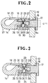
- the loop-like link 12 has a through-opening 16 for receiving one end 11a of the connecting member 11 about which the link 12 is rotatable, an extremity of which end being flanged as at 17 for holding the link 12 against detachment as better shown in Figure 2.
- the connecting member 11 is cylindrical in shape with its opposite end 11b open for receiving a portion of the hook member 14 in a manner hereafter described.
- the connecting member 11 is cut out at its upper peripheral wall to provide an opening 18 in the form of a substantially elongate V-shaped configuration merging with the open end 11b.
- a circular hole 19 is formed in the lower peripheral wall of the connecting member 11 in diametrically opposed relation to the V-shaped opening 18.
- the retaining member 13 in its cylindrical form has a bore 20 sized to snugly receive the connecting member 11 and is provided with a circular hole 21 communicating with the bore 20 and merging with a bevelled cavity 22.
- Extending integrally axially from one end of the retaining member 13 remote from the connecting member 11 is a retaining bar 23 normally positioned in confronting relation to a hook portion of the hook member 14 so that a mouth M defined between respective tip ends of the bar 23 and the hook is closed.
- the hook member 14 has a barrel 24 provided with a pair of diametrically opposed stopper fins 25, 25 and includes a connecting pin 26 extending axially from one end of the barrel 24 through the bore 20 of the retaining member 13 into the connecting member 11 as better shown in Figure 2 and a J-shaped hook 27 extending from the opposite end of the barrel 24 for anchoring a bag link (not shown) in a manner well known in the art.
- the connecting pin 26 has a cross-sectionally circular radial through-hole 28 to be registered with the hole 19 in the connecting member 11 and the hole 21 in the retaining member 13, respectively.
- the retaining pin member 15 is comprised of a disk-like cap portion 29, a rod-like base portion 30 and a coil spring portion 31 interposed therebetween.
- the cap portion 29 has a rounded top projection 29a and a peripherally projecting flange 29b.
- the cylindrical retaining member 13 is fitted over the connecting member 11 from the flange-devoid end thereof and adjusted so that the cap portion 29 of the retaining pin member 15 is exposed through the hole 21 to view in the bevelled cavity 22 of the retaining member 13, in which position the retaining bar 23 is oriented to confront end-to-end with the J-shaped hook 27 thereby closing the mouth M closed.
- the link 12 is finally connected through its opening 16 to the connecting member 11 with the extreme end thereof being then swaged to form the flange 17.
- the link 12 and the connecting member 11 may be formed integrally as depicted in Figure 1.
- the retaining member 13 is first fitted over the connecting member 11, followed by mounting the hook member 14 to which the retaining pin member 15 has previously been connected through the hole 28 in the connecting pin 26, in which instance the cap portion 24 of the pin member 15 is guided progressively along the V-shaped notch 18 in the connecting member 11 until it is exposed to the bevelled cavity 22 and the base portion 30 of the pin member 15 is registered with and fits into the hole 19 opposed to the opening 18, when the retaining bar 23 is held in confronting relation to the J-shaped hook 27 with the mouth M closed.
- Figure 3 shows a modification of the fastening device 10 in which the open end 11b of the connecting member 11 is peripherally tapered as at 32 and the cap 29 and the base 30 of the pin member 15 are also tapered at respective peripheral sides as at 33 and 34, respectively facing the link 12, the arrangement being that mounting of the hook member 14 with the pin member 15 relative to the connecting member 11 is done with greater ease and smoothness.
- Figure 4 shows a modified form of retaining pin member 15 in which the cap 29 and the base 30 are cut out to form pockets 29c and 30' respectively for receiving the coil spring 31 stably in place when assembling with the hook member 14.
- Figure 5 illustrates another modification of the fastening device 10 wherein the cylindrical portion of the connecting member 11 is reduced in diameter and the connecting pin 26 of the hook member 14 is made cylindrical and hollow so that the connecting member 11 may be inserted through the connecting pin 26, an arrangement alternative to the basic construction hereinabove described.
Landscapes
- Engineering & Computer Science (AREA)
- General Engineering & Computer Science (AREA)
- Mechanical Engineering (AREA)
- Hooks, Suction Cups, And Attachment By Adhesive Means (AREA)
- Slide Fasteners, Snap Fasteners, And Hook Fasteners (AREA)
- Buckles (AREA)
Applications Claiming Priority (2)
| Application Number | Priority Date | Filing Date | Title |
|---|---|---|---|
| JP29691/93U | 1993-05-10 | ||
| JP029691U JPH0682425U (ja) | 1993-05-10 | 1993-05-10 | 回転型ナス環 |
Publications (1)
| Publication Number | Publication Date |
|---|---|
| EP0628738A1 true EP0628738A1 (de) | 1994-12-14 |
Family
ID=12283138
Family Applications (1)
| Application Number | Title | Priority Date | Filing Date |
|---|---|---|---|
| EP94303086A Ceased EP0628738A1 (de) | 1993-05-10 | 1994-04-28 | Befestigungsvorrichtung |
Country Status (5)
| Country | Link |
|---|---|
| US (1) | US5499432A (de) |
| EP (1) | EP0628738A1 (de) |
| JP (1) | JPH0682425U (de) |
| KR (1) | KR940026837U (de) |
| CN (1) | CN1109146A (de) |
Cited By (5)
| Publication number | Priority date | Publication date | Assignee | Title |
|---|---|---|---|---|
| US6846140B2 (en) | 2000-10-25 | 2005-01-25 | Nissan Design America, Inc. | Flexible truck bed tie-down system |
| US7070374B2 (en) | 2003-01-03 | 2006-07-04 | Nissan Technical Center North America, Inc. | Track slot fastener |
| US7175377B2 (en) | 2003-01-03 | 2007-02-13 | Nissan Technical Center North America, Inc. | Track slot fastener |
| EP2194283A1 (de) * | 2008-12-08 | 2010-06-09 | Han Lien International Corporation | Drehhakenanordnung |
| WO2010130431A1 (en) * | 2009-05-13 | 2010-11-18 | Enrico Teruzzi | Mooring device for boats |
Families Citing this family (10)
| Publication number | Priority date | Publication date | Assignee | Title |
|---|---|---|---|---|
| US5735451A (en) * | 1993-04-05 | 1998-04-07 | Seiko Epson Corporation | Method and apparatus for bonding using brazing material |
| US6401312B1 (en) * | 2001-02-21 | 2002-06-11 | Chang Hau Co., Ltd. | Hanging hook |
| JP4667661B2 (ja) * | 2001-07-02 | 2011-04-13 | 株式会社永木精機 | 安全フック |
| JP4468051B2 (ja) * | 2003-05-15 | 2010-05-26 | 有限会社 エー・ジー・ケー | 物品吊り下げシステム、スライド式ワイヤー留め具、脱着自在ワイヤー留め具、ワイヤーフック及びワイヤーグリッパー |
| WO2012072095A1 (de) * | 2010-12-02 | 2012-06-07 | Pewag Austria Gmbh | Ringschraube |
| CN105485105B (zh) * | 2016-01-22 | 2018-02-02 | 深圳利亚德光电有限公司 | 连接结构及具有其的led显示装置 |
| CN108087412A (zh) * | 2018-01-30 | 2018-05-29 | 海盐储鑫紧固件厂 | 一种可收纳的挂钩 |
| US11092211B2 (en) * | 2018-11-06 | 2021-08-17 | Duraflex Hong Kong Limited | Swivel connector |
| US11078953B2 (en) * | 2018-11-06 | 2021-08-03 | Duraflex Hong Kong Limited | Swivel connector |
| CN218408117U (zh) * | 2022-10-01 | 2023-01-31 | 深圳市莫非特科技有限公司 | 一种挂钩 |
Citations (2)
| Publication number | Priority date | Publication date | Assignee | Title |
|---|---|---|---|---|
| US3545051A (en) * | 1968-09-11 | 1970-12-08 | Columbus Mckinnon Corp | Safety hook |
| JPH02107814U (de) * | 1989-02-15 | 1990-08-28 |
Family Cites Families (3)
| Publication number | Priority date | Publication date | Assignee | Title |
|---|---|---|---|---|
| US1595264A (en) * | 1924-09-25 | 1926-08-10 | Isaack A Treiman | Bull hook |
| US2728967A (en) * | 1953-02-11 | 1956-01-03 | Bullard Co | Safety hook |
| JPH02107814A (ja) * | 1988-10-14 | 1990-04-19 | Yaskawa Electric Mfg Co Ltd | 磁気軸受装置 |
-
1993
- 1993-05-10 JP JP029691U patent/JPH0682425U/ja active Pending
-
1994
- 1994-04-28 EP EP94303086A patent/EP0628738A1/de not_active Ceased
- 1994-05-09 CN CN94105373A patent/CN1109146A/zh active Pending
- 1994-05-09 US US08/239,562 patent/US5499432A/en not_active Expired - Fee Related
- 1994-05-09 KR KR2019940010177U patent/KR940026837U/ko not_active Abandoned
Patent Citations (2)
| Publication number | Priority date | Publication date | Assignee | Title |
|---|---|---|---|---|
| US3545051A (en) * | 1968-09-11 | 1970-12-08 | Columbus Mckinnon Corp | Safety hook |
| JPH02107814U (de) * | 1989-02-15 | 1990-08-28 |
Cited By (11)
| Publication number | Priority date | Publication date | Assignee | Title |
|---|---|---|---|---|
| US6846140B2 (en) | 2000-10-25 | 2005-01-25 | Nissan Design America, Inc. | Flexible truck bed tie-down system |
| US8550757B2 (en) | 2000-10-25 | 2013-10-08 | Nissan North America, Inc. | Flexible truck bed tie-down system |
| US7070374B2 (en) | 2003-01-03 | 2006-07-04 | Nissan Technical Center North America, Inc. | Track slot fastener |
| US7175377B2 (en) | 2003-01-03 | 2007-02-13 | Nissan Technical Center North America, Inc. | Track slot fastener |
| US7390154B2 (en) | 2003-01-03 | 2008-06-24 | Nissan Technical Center North America, Inc. | Track slot fastener |
| US7547170B2 (en) | 2003-01-03 | 2009-06-16 | Nissan Technical Center North America, Inc. | Track slot fastener |
| US7594787B2 (en) | 2003-01-03 | 2009-09-29 | Nissan Technical Center North America, Inc. | Track slot fastener |
| US7976256B2 (en) | 2003-01-03 | 2011-07-12 | Nissan Technical Center North America, Inc. | Track slot fastener |
| US8408853B2 (en) | 2003-01-03 | 2013-04-02 | Nissan Technical Center North America, Inc. | Track system |
| EP2194283A1 (de) * | 2008-12-08 | 2010-06-09 | Han Lien International Corporation | Drehhakenanordnung |
| WO2010130431A1 (en) * | 2009-05-13 | 2010-11-18 | Enrico Teruzzi | Mooring device for boats |
Also Published As
| Publication number | Publication date |
|---|---|
| JPH0682425U (ja) | 1994-11-25 |
| US5499432A (en) | 1996-03-19 |
| CN1109146A (zh) | 1995-09-27 |
| KR940026837U (ko) | 1994-12-09 |
Similar Documents
| Publication | Publication Date | Title |
|---|---|---|
| US5499432A (en) | Fastening device | |
| US4982581A (en) | Coupling device for ornamental piece | |
| CA2111276C (en) | Decorative pull tab | |
| US5101541A (en) | Snap button | |
| US6510592B1 (en) | Clip for attaching pouches and similar devices | |
| US5603532A (en) | Grab rings | |
| US6163938A (en) | Garment fastener | |
| US5143500A (en) | Snap engaging fastener system for providing rotary motion | |
| EP0260959B1 (de) | Riemenbefestigung | |
| US4382570A (en) | Draw band line support | |
| ATE215187T1 (de) | Karabinerhaken mit verriegelungsvorrichtung | |
| JPH0591905A (ja) | バツクル | |
| US5067265A (en) | Badge and mounting assembly | |
| GB2137476A (en) | Button | |
| JPH0932839A (ja) | ナス環 | |
| US3911537A (en) | Fastener | |
| US5008985A (en) | Zipper securing device | |
| US4790161A (en) | Keyring accessory | |
| US5139144A (en) | Socket wrench storage device | |
| WO2022203831A1 (en) | Locking magnetic fasteners | |
| US4694667A (en) | Permanent padlock-chain assembly | |
| CN107259717A (zh) | 搭扣 | |
| US4704772A (en) | Snap-fit clasp fastener for bags | |
| EP0577270B1 (de) | Verschluss | |
| EP0532640A1 (de) | Hakenverband für tragbare behälter |
Legal Events
| Date | Code | Title | Description |
|---|---|---|---|
| PUAI | Public reference made under article 153(3) epc to a published international application that has entered the european phase |
Free format text: ORIGINAL CODE: 0009012 |
|
| AK | Designated contracting states |
Kind code of ref document: A1 Designated state(s): DE FR GB IT |
|
| 17P | Request for examination filed |
Effective date: 19950315 |
|
| 17Q | First examination report despatched |
Effective date: 19960422 |
|
| GRAG | Despatch of communication of intention to grant |
Free format text: ORIGINAL CODE: EPIDOS AGRA |
|
| STAA | Information on the status of an ep patent application or granted ep patent |
Free format text: STATUS: THE APPLICATION HAS BEEN REFUSED |
|
| 18R | Application refused |
Effective date: 19970501 |