EP0628757A1 - Gegen unberechtigte Betätigung gesicherter selbstschliessender Kran - Google Patents
Gegen unberechtigte Betätigung gesicherter selbstschliessender Kran Download PDFInfo
- Publication number
- EP0628757A1 EP0628757A1 EP94401172A EP94401172A EP0628757A1 EP 0628757 A1 EP0628757 A1 EP 0628757A1 EP 94401172 A EP94401172 A EP 94401172A EP 94401172 A EP94401172 A EP 94401172A EP 0628757 A1 EP0628757 A1 EP 0628757A1
- Authority
- EP
- European Patent Office
- Prior art keywords
- push button
- groove
- fixing member
- hub
- slide
- Prior art date
- Legal status (The legal status is an assumption and is not a legal conclusion. Google has not performed a legal analysis and makes no representation as to the accuracy of the status listed.)
- Granted
Links
Images

Classifications
-
- F—MECHANICAL ENGINEERING; LIGHTING; HEATING; WEAPONS; BLASTING
- F16—ENGINEERING ELEMENTS AND UNITS; GENERAL MEASURES FOR PRODUCING AND MAINTAINING EFFECTIVE FUNCTIONING OF MACHINES OR INSTALLATIONS; THERMAL INSULATION IN GENERAL
- F16K—VALVES; TAPS; COCKS; ACTUATING-FLOATS; DEVICES FOR VENTING OR AERATING
- F16K21/00—Fluid-delivery valves, e.g. self-closing valves
- F16K21/04—Self-closing valves, i.e. closing automatically after operation
- F16K21/06—Self-closing valves, i.e. closing automatically after operation in which the closing movement, either retarded or not, starts immediately after opening
- F16K21/10—Self-closing valves, i.e. closing automatically after operation in which the closing movement, either retarded or not, starts immediately after opening with hydraulic brake cylinder acting on the closure member
-
- F—MECHANICAL ENGINEERING; LIGHTING; HEATING; WEAPONS; BLASTING
- F16—ENGINEERING ELEMENTS AND UNITS; GENERAL MEASURES FOR PRODUCING AND MAINTAINING EFFECTIVE FUNCTIONING OF MACHINES OR INSTALLATIONS; THERMAL INSULATION IN GENERAL
- F16K—VALVES; TAPS; COCKS; ACTUATING-FLOATS; DEVICES FOR VENTING OR AERATING
- F16K31/00—Actuating devices; Operating means; Releasing devices
- F16K31/44—Mechanical actuating means
- F16K31/60—Handles
Definitions
- the present invention relates to a reinforced tamper-evident assembly device for a self-closing tap.
- This device relates, more particularly, to valves having a body, in a single part, in which a "cartridge” is screwed which constitutes an assembly comprising all the organs necessary for the operation of the valve, said body forming a covering.
- Such a cartridge is described in the French patent published under the number 2391406 and it comprises, in its simplest form, a seat, a valve, the valve stem and the timing mechanism.
- the push button is fixed to the free end of the valve stem using an axial screw.
- the present invention relates to a device for concealing the element for fixing the cartridge in the valve body and that for fixing the push-button on the valve stem.
- the body has at its upper part a skirt surrounding the cartridge fixing member, said skirt comprising a slide, which can be moved along the axis of the valve, and having a hole allowing access to the 'fixing member of the push button, said hole being masked by said skirt when the push button is fixed.
- the fixing member of the push button is constituted by a needle screw, arranged radially, screwed into the central hub of said push button which covers the free end of the valve stem.
- the fixing member of the push button exerts an axial force on the valve stem to press the end of said stem against the bottom of the blind bore of the aforementioned hub.
- the sliding shutter is carried by a ring immobilized axially and in rotation relative to the body.
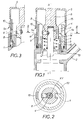
- 1 designates the valve body, molded in a single part, having a spout 2 for leaving the water.
- valve mechanism consists of a cartridge 3 engaged in the body 1 and screwed to the upper part of the latter.
- the cartridge 3 has a rod 4 for controlling the movement of the usual valve. This rod extends beyond the cartridge 3 and is usually mechanically connected to the push button 5.
- the push button has a hub 6 comprising a housing 7, constituted by a blind bore, covering the end of the valve stem 4.
- the fixing of the button 5 on the stem 4 is carried out by a fixing 8.
- the rotation of the member 8 with a view to securing the button 5 on the rod is carried out using a tool, such as a male hexagonal key, passing through a hole 9 of a slide 10 capable to be moved in the direction of the valve's XY axis.
- the slide 10 has an external notch 11 allowing, using a tool such as the tip of a screwdriver, to maneuver said slide to bring it from the position shown in Figure 1 to that shown in Figure 3 so as to make the axis of the hole 9 coincide with that of the member 8.
- the slide 10 is carried by a ring 12 engaged in the body 1 and immobilized in rotation relative to the latter.
- the ring 12 forms a skirt closing off the space between the upper part 1a of the body and the lower part 5a of the button 5.
- the upper end of the ring 12 is normally covered by the lower end of the button 5.
- the ring 12 is forcibly engaged in the body 1 and cannot move freely along the XY axis.
- the ring 12 has an axial finger 13 capable of entering a housing of the body 1.
- This finger 13 performs a double function: it angularly positions the ring relative to the body and immobilizes it in rotation.
- the ring 12 has a radial finger 14 engaged in a groove 15 of the hub 6. In this way, the rotation of the button 5 and, consequently, that of the rod 4, is prevented. This arrangement avoids pivoting the rod 4 and, consequently, opposes the rotation of the valve against its seat.
- the fixing member 8 is constituted by a needle screw which theoretically must ensure good fixing. In fact, experience has shown that this method of fixation was not sufficiently reliable. In fact, the valve is subjected to vibrations which result either from the pressure of the water or from repeated depressions of the button 5, which can cause the screw 8 to be released.
- the rod 4 has a groove 16 providing a shoulder 17 and the locking member is designed so as to exert under the shoulder 17 a force which tends to move the rod 4 according to the arrow F1 by compressing between its end and the bottom of the blind bore 7 is an elastically deformable member such as a rubber washer 18.
- the locking member consists of a cylinder 19 having at its end a cam 20 capable, during the rotation of said cylinder, of being supported under the shoulder 17.
- the cylinder 19 has a radial finger 21 guided in a groove 22 of the hub 6.
- the groove 22 is provided on a sleeve 23 immobilized, axially and in rotation, in the hub 6 of the button.
- the immobilization of the sleeve is obtained, for example, by crimping.
- the sleeve 23 is made of an elastically deformable material and has a slot 24 whose width is less than the diameter of the finger 21.
- the fastener 19 is forcibly engaged in the sleeve 23 by a movement along the arrow F2, the finger 21 passing through the slot 24 to come to be housed in the groove 22.
- the sleeve is engaged on the hub 6 which has a recess 25 for receiving a finger 26 of the sleeve 23 having the function of limiting the sinking of said sleeve and of positioning it angularly.
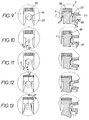
- FIGS. 9 to 13 illustrate the mode of action of the locking member described with reference to FIGS. 4 to 8.
- the groove 22 has two portions: a helical portion and a circular portion.
- the member 19 When the button is put in place, the member 19 is in the escaniotée position (fig.9) and the finger 21 is at one of the ends of the helical portion.
- the cam 20 By rotating the member 19 about its axis ZW, the cam 20 is made to penetrate the groove (FIG. 10), the finger 21 describes the helical portion of the groove 22.
- the last part of the circular portion of the groove could be helical with a very slight slope.
- the winding of the propeller can be in the same direction as that of the above-mentioned helical portion or reversed.
Landscapes
- Engineering & Computer Science (AREA)
- General Engineering & Computer Science (AREA)
- Mechanical Engineering (AREA)
- Preventing Unauthorised Actuation Of Valves (AREA)
- Control Of Electrical Variables (AREA)
- Axle Suspensions And Sidecars For Cycles (AREA)
- Magnetically Actuated Valves (AREA)
- Joining Of Building Structures In Genera (AREA)
- Mechanically-Actuated Valves (AREA)
Applications Claiming Priority (2)
| Application Number | Priority Date | Filing Date | Title |
|---|---|---|---|
| FR9307029 | 1993-06-11 | ||
| FR9307029A FR2706572B1 (fr) | 1993-06-11 | 1993-06-11 | Dispositif d'assemblage à inviolabilité renforcée pour robinet à fermeture temporisée. |
Publications (2)
| Publication Number | Publication Date |
|---|---|
| EP0628757A1 true EP0628757A1 (de) | 1994-12-14 |
| EP0628757B1 EP0628757B1 (de) | 1998-01-28 |
Family
ID=9448011
Family Applications (1)
| Application Number | Title | Priority Date | Filing Date |
|---|---|---|---|
| EP94401172A Expired - Lifetime EP0628757B1 (de) | 1993-06-11 | 1994-05-27 | Gegen unberechtigte Betätigung gesicherter selbstschliessender Hahn |
Country Status (4)
| Country | Link |
|---|---|
| EP (1) | EP0628757B1 (de) |
| AT (1) | ATE162882T1 (de) |
| DE (1) | DE69408209T2 (de) |
| FR (1) | FR2706572B1 (de) |
Cited By (2)
| Publication number | Priority date | Publication date | Assignee | Title |
|---|---|---|---|---|
| EP1857474A2 (de) | 2003-01-30 | 2007-11-21 | Chevron Oronite Company LLC | Auf sulfurisiertem Polyisobutylen basierende Verschleiß- und Oxidationshemmer |
| CN108233606A (zh) * | 2016-12-22 | 2018-06-29 | 斯凯孚公司 | 驱动器的手动超控装置 |
Citations (4)
| Publication number | Priority date | Publication date | Assignee | Title |
|---|---|---|---|---|
| US2202971A (en) * | 1937-12-11 | 1940-06-04 | Anton M Vedoe | Faucet |
| CH294817A (de) * | 1950-09-25 | 1953-11-30 | Oederlin Cie Ag | Mit einem Handgriff versehene Ventilspindel. |
| FR2391406A1 (fr) * | 1977-05-20 | 1978-12-15 | Presto Robinets Sa | Perfectionnements aux robinets a fermeture temporisee |
| GB2121932A (en) * | 1982-06-17 | 1984-01-04 | Timothy Paul Warren | Control handle arrangement for a fluid control valve |
-
1993
- 1993-06-11 FR FR9307029A patent/FR2706572B1/fr not_active Expired - Fee Related
-
1994
- 1994-05-27 AT AT94401172T patent/ATE162882T1/de not_active IP Right Cessation
- 1994-05-27 EP EP94401172A patent/EP0628757B1/de not_active Expired - Lifetime
- 1994-05-27 DE DE69408209T patent/DE69408209T2/de not_active Expired - Lifetime
Patent Citations (4)
| Publication number | Priority date | Publication date | Assignee | Title |
|---|---|---|---|---|
| US2202971A (en) * | 1937-12-11 | 1940-06-04 | Anton M Vedoe | Faucet |
| CH294817A (de) * | 1950-09-25 | 1953-11-30 | Oederlin Cie Ag | Mit einem Handgriff versehene Ventilspindel. |
| FR2391406A1 (fr) * | 1977-05-20 | 1978-12-15 | Presto Robinets Sa | Perfectionnements aux robinets a fermeture temporisee |
| GB2121932A (en) * | 1982-06-17 | 1984-01-04 | Timothy Paul Warren | Control handle arrangement for a fluid control valve |
Cited By (2)
| Publication number | Priority date | Publication date | Assignee | Title |
|---|---|---|---|---|
| EP1857474A2 (de) | 2003-01-30 | 2007-11-21 | Chevron Oronite Company LLC | Auf sulfurisiertem Polyisobutylen basierende Verschleiß- und Oxidationshemmer |
| CN108233606A (zh) * | 2016-12-22 | 2018-06-29 | 斯凯孚公司 | 驱动器的手动超控装置 |
Also Published As
| Publication number | Publication date |
|---|---|
| DE69408209T2 (de) | 1998-07-23 |
| FR2706572A1 (fr) | 1994-12-23 |
| EP0628757B1 (de) | 1998-01-28 |
| FR2706572B1 (fr) | 1995-08-25 |
| ATE162882T1 (de) | 1998-02-15 |
| DE69408209D1 (de) | 1998-03-05 |
Similar Documents
| Publication | Publication Date | Title |
|---|---|---|
| EP0571620B1 (de) | Vorrichtung zur schnellen montierung und demontierung einer achse, z.b. ein fahrradpedal | |
| EP0196931A1 (de) | Kabelzug mit selbsttätiger Nachstellvorrichtung | |
| FR2679504A1 (fr) | Serrure de blocage de la direction d'un vehicule. | |
| FR2619177A1 (fr) | Compresseur de ressorts helicoidaux | |
| FR2543629A1 (fr) | Boulon d'ancrage a expansion | |
| FR2638791A1 (fr) | Verrou pour support d'equipement | |
| FR2478718A1 (fr) | Dispositif a reglage automatique pour le blocage, en position fermee, d'une porte coulissante d'un vehicule automobile | |
| EP0536005B1 (de) | Vorrichtung zum schnellen Montieren und Demontieren von zwei aufeinanderliegenden Teilen | |
| EP0102898B1 (de) | Mutter mit automatischer positiver Sicherung | |
| EP0349367B1 (de) | Elektrischer Schalter für einen pneumatischen Bremsservomotor | |
| EP2733267B1 (de) | Element für Straßenbauvorrichtung, entsprechende Straßenbauvorrichtung und Gesamteinheit | |
| EP1853977B1 (de) | Blockierbarer drücker | |
| EP0628757B1 (de) | Gegen unberechtigte Betätigung gesicherter selbstschliessender Hahn | |
| FR2720128A1 (fr) | Dispositif de verrouillage et de blocage en position verrouillée pour tubes montés coulissant l'un dans l'autre. | |
| EP0936128B1 (de) | Lenksystem, Lenkrad und Lenkradsäule für ein solches System | |
| FR2669320A1 (fr) | Tire-bouchon mecanique. | |
| FR2718497A3 (fr) | Dispositif d'assemblage de panneaux par vissage. | |
| EP1000252A1 (de) | Sperrvorrichtung für eine tür eines kraftfahrzeuges | |
| EP0307327A1 (de) | Schraubverbindungensvorrichtung für zwei Elemente mit der Möglichkeit den Abstand dazwischen einzustellen | |
| FR2668738A1 (fr) | Dispositif antivol pour anneau d'attelage. | |
| FR2627445A1 (fr) | Mecanisme de blocage du volant pour vehicules automobiles | |
| EP0606196A1 (de) | Schliessvorrichtung | |
| EP0940529A1 (de) | Doppelsicherheitszylinder | |
| FR2736110A1 (fr) | Organe de liaison filete inviolable | |
| FR2679285A1 (fr) | Systeme de montage de poignees sur une porte. |
Legal Events
| Date | Code | Title | Description |
|---|---|---|---|
| PUAI | Public reference made under article 153(3) epc to a published international application that has entered the european phase |
Free format text: ORIGINAL CODE: 0009012 |
|
| AK | Designated contracting states |
Kind code of ref document: A1 Designated state(s): AT BE CH DE ES FR GB IT LI LU NL PT |
|
| 17P | Request for examination filed |
Effective date: 19950519 |
|
| 17Q | First examination report despatched |
Effective date: 19961104 |
|
| GRAG | Despatch of communication of intention to grant |
Free format text: ORIGINAL CODE: EPIDOS AGRA |
|
| GRAG | Despatch of communication of intention to grant |
Free format text: ORIGINAL CODE: EPIDOS AGRA |
|
| GRAH | Despatch of communication of intention to grant a patent |
Free format text: ORIGINAL CODE: EPIDOS IGRA |
|
| GRAH | Despatch of communication of intention to grant a patent |
Free format text: ORIGINAL CODE: EPIDOS IGRA |
|
| GRAA | (expected) grant |
Free format text: ORIGINAL CODE: 0009210 |
|
| AK | Designated contracting states |
Kind code of ref document: B1 Designated state(s): AT BE CH DE ES FR GB IT LI LU NL PT |
|
| PG25 | Lapsed in a contracting state [announced via postgrant information from national office to epo] |
Ref country code: NL Free format text: LAPSE BECAUSE OF FAILURE TO SUBMIT A TRANSLATION OF THE DESCRIPTION OR TO PAY THE FEE WITHIN THE PRESCRIBED TIME-LIMIT Effective date: 19980128 Ref country code: GB Free format text: LAPSE BECAUSE OF FAILURE TO SUBMIT A TRANSLATION OF THE DESCRIPTION OR TO PAY THE FEE WITHIN THE PRESCRIBED TIME-LIMIT Effective date: 19980128 Ref country code: ES Free format text: THE PATENT HAS BEEN ANNULLED BY A DECISION OF A NATIONAL AUTHORITY Effective date: 19980128 |
|
| REF | Corresponds to: |
Ref document number: 162882 Country of ref document: AT Date of ref document: 19980215 Kind code of ref document: T |
|
| REG | Reference to a national code |
Ref country code: CH Ref legal event code: EP |
|
| REF | Corresponds to: |
Ref document number: 69408209 Country of ref document: DE Date of ref document: 19980305 |
|
| ITF | It: translation for a ep patent filed | ||
| PG25 | Lapsed in a contracting state [announced via postgrant information from national office to epo] |
Ref country code: PT Free format text: LAPSE BECAUSE OF FAILURE TO SUBMIT A TRANSLATION OF THE DESCRIPTION OR TO PAY THE FEE WITHIN THE PRESCRIBED TIME-LIMIT Effective date: 19980428 |
|
| PG25 | Lapsed in a contracting state [announced via postgrant information from national office to epo] |
Ref country code: LU Free format text: LAPSE BECAUSE OF NON-PAYMENT OF DUE FEES Effective date: 19980527 |
|
| PG25 | Lapsed in a contracting state [announced via postgrant information from national office to epo] |
Ref country code: LI Free format text: LAPSE BECAUSE OF NON-PAYMENT OF DUE FEES Effective date: 19980531 Ref country code: CH Free format text: LAPSE BECAUSE OF NON-PAYMENT OF DUE FEES Effective date: 19980531 Ref country code: BE Free format text: LAPSE BECAUSE OF NON-PAYMENT OF DUE FEES Effective date: 19980531 |
|
| NLV1 | Nl: lapsed or annulled due to failure to fulfill the requirements of art. 29p and 29m of the patents act | ||
| GBV | Gb: ep patent (uk) treated as always having been void in accordance with gb section 77(7)/1977 [no translation filed] |
Effective date: 19980128 |
|
| BERE | Be: lapsed |
Owner name: LES ROBINETS PRESTO Effective date: 19980531 |
|
| PLBE | No opposition filed within time limit |
Free format text: ORIGINAL CODE: 0009261 |
|
| STAA | Information on the status of an ep patent application or granted ep patent |
Free format text: STATUS: NO OPPOSITION FILED WITHIN TIME LIMIT |
|
| REG | Reference to a national code |
Ref country code: CH Ref legal event code: PL |
|
| 26N | No opposition filed | ||
| PGFP | Annual fee paid to national office [announced via postgrant information from national office to epo] |
Ref country code: FR Payment date: 20100527 Year of fee payment: 17 |
|
| PGFP | Annual fee paid to national office [announced via postgrant information from national office to epo] |
Ref country code: IT Payment date: 20100527 Year of fee payment: 17 Ref country code: DE Payment date: 20100531 Year of fee payment: 17 Ref country code: AT Payment date: 20100531 Year of fee payment: 17 |
|
| REG | Reference to a national code |
Ref country code: DE Ref legal event code: R119 Ref document number: 69408209 Country of ref document: DE |
|
| REG | Reference to a national code |
Ref country code: DE Ref legal event code: R119 Ref document number: 69408209 Country of ref document: DE |
|
| REG | Reference to a national code |
Ref country code: AT Ref legal event code: MM01 Ref document number: 162882 Country of ref document: AT Kind code of ref document: T Effective date: 20110527 |
|
| REG | Reference to a national code |
Ref country code: FR Ref legal event code: ST Effective date: 20120131 |
|
| PG25 | Lapsed in a contracting state [announced via postgrant information from national office to epo] |
Ref country code: AT Free format text: LAPSE BECAUSE OF NON-PAYMENT OF DUE FEES Effective date: 20110527 Ref country code: IT Free format text: LAPSE BECAUSE OF NON-PAYMENT OF DUE FEES Effective date: 20110527 |
|
| PG25 | Lapsed in a contracting state [announced via postgrant information from national office to epo] |
Ref country code: FR Free format text: LAPSE BECAUSE OF NON-PAYMENT OF DUE FEES Effective date: 20110531 |
|
| PG25 | Lapsed in a contracting state [announced via postgrant information from national office to epo] |
Ref country code: DE Free format text: LAPSE BECAUSE OF NON-PAYMENT OF DUE FEES Effective date: 20111130 |