EP0628833A1 - Système pour contrôler la capacité résiduelle d'une pile - Google Patents
Système pour contrôler la capacité résiduelle d'une pile Download PDFInfo
- Publication number
- EP0628833A1 EP0628833A1 EP94108716A EP94108716A EP0628833A1 EP 0628833 A1 EP0628833 A1 EP 0628833A1 EP 94108716 A EP94108716 A EP 94108716A EP 94108716 A EP94108716 A EP 94108716A EP 0628833 A1 EP0628833 A1 EP 0628833A1
- Authority
- EP
- European Patent Office
- Prior art keywords
- battery
- residual capacity
- electric energy
- capacity
- discharged
- Prior art date
- Legal status (The legal status is an assumption and is not a legal conclusion. Google has not performed a legal analysis and makes no representation as to the accuracy of the status listed.)
- Granted
Links
- 238000012544 monitoring process Methods 0.000 title claims abstract description 12
- 230000007423 decrease Effects 0.000 claims abstract description 10
- 238000007599 discharging Methods 0.000 claims description 34
- 230000009467 reduction Effects 0.000 claims description 8
- 230000001133 acceleration Effects 0.000 claims description 2
- 230000000694 effects Effects 0.000 claims description 2
- 238000002474 experimental method Methods 0.000 description 72
- 238000010586 diagram Methods 0.000 description 6
- 238000000034 method Methods 0.000 description 4
- 230000008569 process Effects 0.000 description 4
- 229910018095 Ni-MH Inorganic materials 0.000 description 3
- 229910018477 Ni—MH Inorganic materials 0.000 description 3
- 238000005070 sampling Methods 0.000 description 3
- 230000000994 depressogenic effect Effects 0.000 description 2
- 238000001514 detection method Methods 0.000 description 2
- 239000004973 liquid crystal related substance Substances 0.000 description 2
- 229910001507 metal halide Inorganic materials 0.000 description 2
- 230000006870 function Effects 0.000 description 1
- 229910052739 hydrogen Inorganic materials 0.000 description 1
- 239000001257 hydrogen Substances 0.000 description 1
- 238000012986 modification Methods 0.000 description 1
- 230000004048 modification Effects 0.000 description 1
- 238000012545 processing Methods 0.000 description 1
- 229910052761 rare earth metal Inorganic materials 0.000 description 1
- 150000002910 rare earth metals Chemical class 0.000 description 1
Images



Classifications
-
- G—PHYSICS
- G01—MEASURING; TESTING
- G01R—MEASURING ELECTRIC VARIABLES; MEASURING MAGNETIC VARIABLES
- G01R31/00—Arrangements for testing electric properties; Arrangements for locating electric faults; Arrangements for electrical testing characterised by what is being tested not provided for elsewhere
- G01R31/36—Arrangements for testing, measuring or monitoring the electrical condition of accumulators or electric batteries, e.g. capacity or state of charge [SoC]
- G01R31/378—Arrangements for testing, measuring or monitoring the electrical condition of accumulators or electric batteries, e.g. capacity or state of charge [SoC] specially adapted for the type of battery or accumulator
- G01R31/379—Arrangements for testing, measuring or monitoring the electrical condition of accumulators or electric batteries, e.g. capacity or state of charge [SoC] specially adapted for the type of battery or accumulator for lead-acid batteries
-
- G—PHYSICS
- G01—MEASURING; TESTING
- G01R—MEASURING ELECTRIC VARIABLES; MEASURING MAGNETIC VARIABLES
- G01R31/00—Arrangements for testing electric properties; Arrangements for locating electric faults; Arrangements for electrical testing characterised by what is being tested not provided for elsewhere
- G01R31/36—Arrangements for testing, measuring or monitoring the electrical condition of accumulators or electric batteries, e.g. capacity or state of charge [SoC]
- G01R31/3644—Constructional arrangements
- G01R31/3648—Constructional arrangements comprising digital calculation means, e.g. for performing an algorithm
-
- G—PHYSICS
- G01—MEASURING; TESTING
- G01R—MEASURING ELECTRIC VARIABLES; MEASURING MAGNETIC VARIABLES
- G01R31/00—Arrangements for testing electric properties; Arrangements for locating electric faults; Arrangements for electrical testing characterised by what is being tested not provided for elsewhere
- G01R31/005—Testing of electric installations on transport means
- G01R31/006—Testing of electric installations on transport means on road vehicles, e.g. automobiles or trucks
-
- G—PHYSICS
- G01—MEASURING; TESTING
- G01R—MEASURING ELECTRIC VARIABLES; MEASURING MAGNETIC VARIABLES
- G01R31/00—Arrangements for testing electric properties; Arrangements for locating electric faults; Arrangements for electrical testing characterised by what is being tested not provided for elsewhere
- G01R31/36—Arrangements for testing, measuring or monitoring the electrical condition of accumulators or electric batteries, e.g. capacity or state of charge [SoC]
- G01R31/392—Determining battery ageing or deterioration, e.g. state of health
-
- Y—GENERAL TAGGING OF NEW TECHNOLOGICAL DEVELOPMENTS; GENERAL TAGGING OF CROSS-SECTIONAL TECHNOLOGIES SPANNING OVER SEVERAL SECTIONS OF THE IPC; TECHNICAL SUBJECTS COVERED BY FORMER USPC CROSS-REFERENCE ART COLLECTIONS [XRACs] AND DIGESTS
- Y02—TECHNOLOGIES OR APPLICATIONS FOR MITIGATION OR ADAPTATION AGAINST CLIMATE CHANGE
- Y02T—CLIMATE CHANGE MITIGATION TECHNOLOGIES RELATED TO TRANSPORTATION
- Y02T10/00—Road transport of goods or passengers
- Y02T10/60—Other road transportation technologies with climate change mitigation effect
- Y02T10/70—Energy storage systems for electromobility, e.g. batteries
-
- Y—GENERAL TAGGING OF NEW TECHNOLOGICAL DEVELOPMENTS; GENERAL TAGGING OF CROSS-SECTIONAL TECHNOLOGIES SPANNING OVER SEVERAL SECTIONS OF THE IPC; TECHNICAL SUBJECTS COVERED BY FORMER USPC CROSS-REFERENCE ART COLLECTIONS [XRACs] AND DIGESTS
- Y10—TECHNICAL SUBJECTS COVERED BY FORMER USPC
- Y10S—TECHNICAL SUBJECTS COVERED BY FORMER USPC CROSS-REFERENCE ART COLLECTIONS [XRACs] AND DIGESTS
- Y10S320/00—Electricity: battery or capacitor charging or discharging
- Y10S320/18—Indicator or display
- Y10S320/21—State of charge of battery
Definitions
- the present invention relates to a battery monitor system for monitoring the residual capacity of a battery such as a lead storage battery mounted on an electric vehicle or the like.
- Electric vehicles are propelled by an electric motor which is supplied with required electric energy from a battery such as a lead storage battery. It has been customary to detect the residual capacity of the battery, i.e., the amount of electric energy that can be discharged from the battery, according to any of various processes on a real-time basis, and display the detected residual capacity on a suitable display unit in the passenger's compartment for recognition by the driver.
- a battery such as a lead storage battery.
- the inventor has found out that the residual capacity of the battery generally varies depending the output voltage of the battery at the time it is discharged, and that the higher the output voltage, the lower the substantial residual capacity of the battery.
- Electric vehicles are generally controlled such that the electric energy supplied from the battery to the electric motor, i.e., the output electric energy from the battery, while the electric vehicle is running is higher causing an increase in the mechanical output energy from the electric motor as the driver depresses the accelerator pedal more deeply. Therefore, it is preferable for the driver to recognize the residual capacity of the battery depending on the present amount of operation of the accelerator pedal or the present depth to which the accelerator pedal is depressed, i.e., the present output electric energy of the battery. If informed of the residual capacity of the battery depending on the present output electric energy of the battery, then the driver can recognize how far the electric vehicle can travel with the present rate of accelerator pedal depression, and hence can appropriately depress the accelerator pedal.
- a battery monitor system for monitoring the residual capacity of a battery, comprising residual capacity determining means for determining the residual capacity of a battery, electric energy detecting means for detecting the output electric energy of the battery when the battery is discharged, residual capacity correcting means for correcting the residual capacity determined by the residual capacity determining means depending on the output electric energy detected by the electric energy detecting means, such that as the output electric energy of the battery increases, a new residual capacity produced when the residual capacity is corrected by the residual capacity correcting means decreases.
- the residual capacity correcting means may comprise means for correcting the residual capacity by subtracting a residual capacity corrective value which increases as the output electric energy of the battery increases, from the residual capacity determined by the residual capacity determining means.
- the battery monitor system may further comprise discharging current detecting means for detecting a discharging current from the battery, and discharging current integrating means for integrating the detected discharging current from the time when the battery starts being discharged, the residual capacity determining means comprising means for determining, as the residual capacity of the battery, a value produced by subtracting the integrated discharging current from an initial capacity of the battery at the time when the battery starts being discharged.
- the battery monitor system may further comprise temperature detecting means for detecting the temperature of the battery, the residual capacity correcting means comprising means for correcting the residual capacity determined by the residual capacity determining means with the temperature detected by the temperature detecting means according to a predetermined rule which takes into account an effect that the temperature of the battery has on the residual capacity of the battery.
- the battery monitor system may further comprise residual capacity displaying means for displaying the new residual capacity.
- the residual capacity displaying means may comprise means for displaying a reduction from the residual capacity determined by the residual capacity determining means to the new residual capacity.
- the battery monitor system may be combined with an electric vehicle comprising an electric motor energizable by the battery for propelling the electric vehicle, and motor control means for controlling electric energy supplied from the battery to the electric motor depending on the amount of acceleration applied to the electric vehicle.
- the residual capacity determined by the residual capacity determining means is corrected such that as the output electric energy of the battery increases, a new residual capacity produced when the residual capacity is corrected by the residual capacity correcting means decreases. It is thus possible to recognize the effective residual capacity depending on the output electric energy of the battery from the new residual capacity thus produced.
- the residual capacity correcting means corrects the residual capacity by subtracting a residual capacity corrective value which increases as the output electric energy of the battery increases, from the residual capacity determined by the residual capacity determining means.
- the discharging current from the battery is detected by the discharging current detecting means, and integrated by the discharging current integrating means, and a value produced by subtracting the integrated discharging current from an initial capacity of the battery at the time when the battery starts being discharged is determined as the residual capacity of the battery.
- the temperature of the battery is detected by the temperature detecting means, and the residual capacity is corrected with the temperature detected by the temperature detecting means.
- the temperature of the battery is taken into account because the residual capacity of the battery varies depending on the battery temperature as well as the output electric energy from the battery.
- the residual capacity displaying means allows the displayed new residual capacity to be easily recognized visually.
- the residual capacity displaying means also displays a reduction from the residual capacity determined by the residual capacity determining means to the new residual capacity.
- the reduction in the residual capacity depending on the output electric energy of the battery can easily be recognized visually.
- the driver of the electric vehicle can visually recognize the effective residual capacity of the battery depending on the amount of operation of the accelerator pedal of the electric vehicle.
- a battery monitor system for monitoring the residual capacity of a battery is typically incorporated in an electric vehicle, for example.
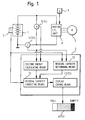
- the battery monitor system includes a battery 1, a controller 2 for carrying out various arithmetic operations to detect and monitor the residual capacity of the battery 1, a voltage sensor 3 for detecting the output voltage of the battery 1, a current sensor (current detecting means) 4 for detecting a charging or discharging current of the battery 1, a temperature sensor (temperature detecting means) 5 for detecting the temperature T of the battery 1, a residual capacity display unit 6 for displaying the residual capacity of the battery 1, an electric motor 7 for propelling the electric vehicle, a motor control unit (motor control means) 8 for controlling the electric motor 8, and an accelerator operation sensor 9 comprising a potentiometer or the like for detecting the amount A of operation of an accelerator pedal, e.g., the depth to which the accelerator pedal is depressed.
- the battery 1 may comprise, for example, a nickel-metal-halide battery (nickel-hydrogen battery).
- the motor control unit 8 controls the supply of electric energy from the battery 1 to the electric motor 7 to energize the electric motor 7. Basically, when the amount A of operation of the accelerator pedal as detected by the accelerator operation sensor 9 is greater, the motor control unit 8 increases the amount of output electric power supplied from the battery 1 to the electric motor 7, for thereby increasing the mechanical output energy from the electric motor 7.
- the mechanical output energy from the electric motor 7 is transmitted through a power transmitting system (not shown) to drive wheels (not shown) of the electric vehicle.
- the controller 2 comprises an electronic circuit including a central processing unit (CPU), a random-access memory (RAM), a read-only memory (ROM), etc.
- the controller 2 functionally has a residual capacity determining means 10 for calculating the residual capacity of the battery 1 in a manner described later based on a discharging current I detected by the current sensor 4 when the battery 1 is being discharged, i.e., when the electric vehicle is running, and a battery temperature T detected by the temperature sensor 5, an electric energy calculating means 11 for determining the output electric energy W from the battery 1 according to the equation (1) given below based on the discharging current I detected by the current sensor 4 when the battery 1 is being discharged and an output voltage V detected across the battery 1 by the voltage sensor 5, a residual capacity correcting means 12 for correcting the residual capacity of the battery 1 determined by the residual capacity determining means 10 based on the output electric energy W calculated by the electric energy calculating means 11 and the battery temperature T detected by the temperature sensor 5, and a display driving means 13 for displaying the residual capacity corrected by the
- the current sensor 4, the voltage sensor 3, and the electric energy calculating means 11 jointly serve as an electric energy detecting means 14 for detecting the output electric energy W from the battery 1 when the battery 1 is being discharged.
- the residual capacity display unit 6 and the display driving means 13 jointly serve as a residual capacity displaying means 15 for displaying the residual capacity of the battery 1.
- the residual capacity display unit 6 comprises a bar-graph display unit which indicates the residual capacity of the battery 1 with a bar graph.
- the controller 2 detects the present discharging current I from the battery 1 through the current sensor 4 in a sufficient short sampling time in a step 2. Then, the controller 2 integrates the detected discharging current I from the time when the battery 1 starts being discharged, according to the equation (2) below, and determines the integrated value as an integrated discharged quantity in a step 3. where ⁇ t is the sampling time.
- the integrated discharged quantity calculated according to the equation (2) represents the total discharged quantity (coulomb) from the time when the battery 1 starts being discharged to the present time.
- the controller 2 detects the present output voltage V of the battery 1 through the voltage sensor 3 and also detects the battery temperature T through the temperature sensor 5 in a step 4.
- the controller 2 calculates the output electric energy W of the battery 1 according to the equation (1) above based on the discharging current I detected in the step 2 and the output voltage V detected in the step 4.
- the controller 2 determines, with the residual capacity correcting means 12, a dischargeable capacity from the battery temperature T detected in the step 4 and the output electric energy W calculated in the step 5, using a predetermined data table shown in FIG. 3.
- the dischargeable capacity is plotted as a function of the output density and the battery temperature. The data shown in FIG.
- the data shown in FIG. 3 have such a basic trend that as the output density increases, the dischargeable capacity decreases, and as the battery temperature decreases, the dischargeable capacity decreases.
- the data includes a data area in which as the battery temperature increases in a relatively high battery temperature range, the dischargeable capacity slightly decreases.
- the dischargeable capacity is determined from the present battery temperature T and the output electric energy W using the data table shown in FIG. 3. For example, when the output density corresponding substantially to the present output electric energy is 50 (W/kg) and the battery temperature T is 0°C, the dischargeable capacity determined from the data table shown in FIG. 3 is about 20 (Ah).
- Reference residual capacity Initial storage capacity - Integrated discharged quantity (3)
- the initial capacity is the capacity of the battery 1 at the time when the battery 1 starts being discharged (the electric vehicle starts running) in the step 1. If the battery 1 has been fully charged before it starts being discharged in a present cycle, i.e., before the electric vehicle starts running, then the initial capacity is set to the capacity of the battery 1 when it is fully charged. If the battery 1 has not been charged before it starts being discharged in a present cycle, then the initial capacity is set to the reference residual capacity at the time when the battery 1 stopped being discharged in a preceding cycle, i.e., when the electric vehicle stopped running.
- Each of the reference residual capacity determined according to the equation (3) and the initial capacity represents a total quantity of electric energy that can be discharged from the battery 1 when the battery 1 is charged under certain given conditions.
- such given conditions are a discharging current of 6 A and a cutoff voltage (which is the output voltage of the battery 1 at the time it is fully discharged) of 1 V.
- the initial capacity represents a total quantity of electric energy which is obtained when the battery 1 is discharged at a discharging current of 6 A until the cutoff voltage is reached, i.e., until the output voltage becomes 1 V, before the electric vehicle starts running.
- the reference residual capacity represents a total quantity of electric energy which is obtained when the battery 1 at present is discharged under the same conditions.
- the initial capacity may be estimated from an open-circuit voltage of the battery 1, i.e., the output voltage of the battery 1 when it is open or is not connected to any load, before the battery 1 starts being discharged.
- Residual capacity corrective value Fully charged reference capacity - Dischargeable quantity (4) where the fully charged reference capacity represents the capacity of the battery 1 when it has been discharged from the fully charged condition with the discharging current of 6 A and the cutoff voltage of 1 V.
- the fully charged reference capacity is the same as the initial capacity or the reference residual capacity at the time when the battery 1 starts being discharged.
- the residual capacity corrective value which is obtained by subtracting the dischargeable quantity from the fully charged reference capacity represents a quantity of electric energy that cannot be extracted from the battery 1 at the output electric energy W and the battery temperature T at present, i.e., a reduction in the storage quantity depending on the output electric energy W and the battery temperature T at present.
- the dischargeable quantity is smaller as the output electric energy W of the battery 1 is greater
- the residual capacity corrective value is greater as the output electric energy W of the battery 1 is greater, i.e., as the amount A of operation of the accelerator pedal is greater.
- the controller 2 corrects, with the residual capacity correcting means 12, the reference residual capacity determined according to the equation (3) with the residual capacity corrective value determined according to the equation (4), according to the following equation (5), thereby to determine an effective residual capacity, i.e., a residual dischargeable quantity in a step 9:
- Effective residual capacity Reference residual capacity - Residual capacity corrective value (5)
- the residual capacity determined according to the equation (5) represents an effective total quantity of electric energy that can be discharged by the battery 1 at the output electric energy W and the battery temperature T at present. Since the residual capacity corrective value is greater as the output electric energy W is greater, the residual capacity determined according to the equation (5) is smaller as the output electric energy W is greater.
- the controller 2 displays, with the display driving means 13, the residual capacity determined according to the equation (5) and the residual capacity corrective value determined according to the equation (4) on the residual capacity display unit 6 in a step 10.
- the display of these data will be described in detail later on.
- the controller 2 determines whether the battery 1 is being discharged or not in a step 11. If the battery 1 still continues to be discharged, i.e., if the electric vehicle is running, (YES in the step 11), then the controller 2 repeats the process after the step 2 in the sampling time ⁇ t. If the electric vehicle stops running and the battery 1 stops being discharged (NO in the step 11), then the operation sequence shown in FIG. 2 is finished.
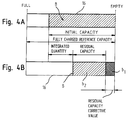
- the residual capacity display unit 6 comprises a liquid crystal display element, for example, for displaying the residual capacity and the residual capacity corrective value with a bar graph B within a slender horizontal rectangular frame 16.
- one end (right-hand end in FIG. 4A in the embodiment) of the rectangular frame 16 indicates an "EMPTY"' position which represents that the battery 1 is fully discharged, and the other end (left-hand end in FIG. 4A in the embodiment) of the rectangular frame 16 indicates a "FULL" position which represents that the battery 1 is fully charged.
- the bar graph B which has a length depending on the initial capacity and extends from the "EMPTY" position toward the "FULL” position is displayed as liquid crystal display dots (shown hatched) in the rectangular frame 16. The full length of the bar graph B corresponds to the fully charged reference capacity.
- the initial capacity of the battery 1 corresponds to the fully charged reference capacity
- the bar graph B is displayed across the entire length of the rectangular frame 16.
- the length of the bar graph B from the "EMPTY" position is also reduced.
- the bar graph B displayed in the rectangular frame 16 has a length from the "EMPTY" position, which is 3/4 of the entire length of the rectangular frame 16. Therefore, the driver of the electric vehicle can visually recognize the initial capacity of the battery 1 based on the length of the bar graph B with respect to the entire length of the rectangular frame 16.
- the length of the bar graph B from the "EMPTY” position is reduced by a value corresponding to the integrated discharged quantity.
- a bar graph portion b1 (shown stippled) having a length from the "EMPTY” position, which corresponds to the residual capacity corrective value at present, is displayed in the bar graph B in a pattern different from the pattern of a remaining bar graph portion b2 (shown hatched).
- the bar graph portion b1 may be displayed as a de-energized area of the bar graph portion b2 or in a color different from the bar graph portion b2.
- the length of the bar graph B from the "EMPTY" position corresponds to the reference residual capacity. Since the bar graph portion b1 corresponds to the residual capacity corrective value depending on the output electric energy W and the battery temperature T at present, the length of the bar graph portion b2 corresponds to the effective residual capacity depending on the output electric energy W and the battery temperature T at present as can be seen from the equation (5).
- the bar graph portion b1 will hereinafter be referred to as a "corrective value display portion b1", and the bar graph portion b2 as a "residual capacity display portion b2".
- the driver of the electric vehicle can visually recognize the effective residual capacity depending on the output electric energy W and the battery temperature T at present, stated otherwise, the amount A of operation of the accelerator pedal and the battery temperature T at present.
- the driver can also visually recognize, from the length of the corrective value display portion b1, a reduction in the residual capacity of the battery 1 depending on the amount A of operation of the accelerator pedal and the battery temperature T at present.
- the boundary between the corrective value display portion b1 and the residual capacity display portion b2 indicates a virtual "EMPTY" position for the residual capacity of the battery 1. This virtual "EMPTY" position moves in the rectangular frame 16 as the output electric energy W of the battery 1 varies, stated otherwise, as the amount A of operation of the accelerator pedal varies.
- the sum of the lengths of the corrective value display portion b1 and the residual capacity display portion b2 becomes shorter as the battery 1 is continuously discharged.
- the length of the corrective value display portion b1 becomes nil, and only the residual capacity display portion b2 is displayed.
- the inventor conducted experiments on storage batteries (Ni-MH batteries) of a rated capacity of 25 Ah which have rare-earth metal-halide cells as follows:
- a storage battery was fully charged for 12 hours with a charging current of 3 A at a battery temperature of 30°C, and then discharged to given quantities of discharged electric energy.
- the quantities of discharged electric energy represented measured discharging currents integrated with respect to time (see the equation (2) above), and had values of 20 Ah and 12.5 Ah, respectively.
- the storage battery was discharged in a variable-current mode in which the discharging current had various values and a constant-current mode in which the discharging current had a constant value.
- the Experiment 1 is an experiment for simulating the steps 1 through 3 shown in FIG. 2, and the quantities of discharged electric energy which have the values of 20 Ah and 12.5 Ah represent integrated discharged quantities described above.
- the storage battery which was subjected to the Experiment 1 was discharged at the same temperature as in the Experiment 1 with the output density of 50 W/kg (constant) and the cutoff voltage of 1 V, and the discharging current integrated with respect to time was measured.
- the Experiment 2 (which is also referred to as an "Experiment 2a") is an experiment for measuring an actual residual capacity of the storage battery which was discharged in the Experiment 1, at the battery temperature of 30°C and the output density of 50 W/kg.
- Experiment 2b A fully charged storage battery which was not discharged in the Experiment 1 was also discharged at the same temperature as in the Experiment 1 with the output density of 50 W/kg (constant) and the cutoff voltage of 1 V, and the discharging current integrated with respect to time was measured.
- This Experiment (which is also referred to as an "Experiment 2b") is an experiment for measuring an actual residual capacity of the storage battery whose integrated discharged quantity is nil, at the battery temperature of 30°C and the output density of 50 W/kg.
- the residual capacity measured in the Experiment 2b corresponds to the dischargeable capacity.
- the storage batteries which were subjected to the Experiment 2 were discharged at the same temperature as in the Experiment 1 at a discharging current of 6A and a cutoff voltage of 1 V, and the quantities of discharged energy were measured.
- the Experiment 3 (which is also referred to as an "Experiment 3a") is an experiment for measuring a capacity which cannot be discharged in the Experiment 2, the capacity corresponding to the residual capacity corrective value.
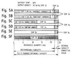
- FIGS. 5A ⁇ 5F show bar graphs representing the quantities of discharged electric energy and their sums which were obtained in the Experiments 1, 2a, 3a.
- the bar graph shown in FIG. 5A represents the experimental results produced when the storage battery was discharged at 20 Ah in the variable-current mode in the Experiment 1.
- the bar graph shown in FIG. 5B represents the experimental results produced when the storage battery was discharged at 20 Ah in the constant-current mode in the Experiment 1.
- the bar graph shown in FIG. 5C represents the experimental results produced when the storage battery was discharged at 12.5 Ah in the variable-current mode in the Experiment 1.
- FIG. 5D represents the experimental results produced when the storage battery was discharged at 12.5 Ah in the constant-current mode in the Experiment 1.
- FIG. 5E shows a bar graph representing the quantities of discharged electric energy and their sum which were obtained in the Experiments 2b, 3a.
- FIG. 5F shows a bar graph representing the quantity of discharged electric energy which was obtained in the Experiment 3b.
- the quantity of discharged electric energy in the Experiment 3b shown in FIG. 5F represents the fully charged reference capacity of the battery.
- the quantity of discharged electric energy in the Experiment 2b shown in FIG. 5D represents the residual capacity (dischargeable capacity) of the battery at the time the battery started being discharged at the battery temperature of 30°C and the output density of 50 W/kg.
- the quantities of discharged electric energy in the Experiment 2a shown in FIGS. 5A ⁇ 5D represent the residual capacities measured at the battery temperature of 30°C and the output density of 50 W/kg after the battery was discharged in the Experiment 1.
- the quantities of discharged electric energy in the Experiment 3 shown in FIGS. 5A ⁇ 5E represent capacities that could not be discharged in the Experiment 2.
- 5A ⁇ 5F also show residual capacity corrective values determined according to the equation (4), in lengths commensurate with the lengths of the bar graphs.
- the quantity of discharged electric energy in the Experiment 3b shown in FIG. 5F and the quantity of discharged electric energy (which is in agreement with the dischargeable capacity obtained from the data table shown in FIG. 3) in the Experiment 2b shown in FIG. 5E were used respectively as the fully charged reference capacity and the dischargeable capacity in the equation (4).
- the initial capacity of a battery is equal to the capacity of the battery when it is fully charged, i.e., the fully charged reference capacity of the battery, then as is apparent from the equations (3) through (5), the sum of the integrated quantity of discharged electric energy from the time when the battery starts being discharged and the residual capacity which is finally determined is equal to the dischargeable quantity.
- the sums of the integrated quantities of discharged electric energy in the Experiment 1 and the measured residual capacities in the Experiment 2 in FIGS. 5A ⁇ 5D agreed highly accurately with the dischargeable quantity in the Experiment 2b in FIG. 5E as shown in Table given below if the dischargeable quantity in the Experiment 2b in FIG. 5E was 100 %.
- SUM 1 The quantity of discharged electric energy in the Experiment 1 + the quantity of discharged electric energy in the Experiment 2 (dischargeable capacity: 100 %)
- SUM 2 The quantity of discharged electric energy in the Experiment 1 + the quantity of discharged electric energy in the Experiment 2 + quantity of discharged electric energy in the Experiment 3 (fully charged reference capacity: 100%)
- the sum of the integrated quantity of discharged electric energy from the time the battery starts being discharged the residual capacity determined finally, and the residual capacity corrective value agrees with the fully charged reference capacity.
- the residual capacity corrective value determined according to the equation (4) is highly accurate as representing a capacity that cannot be discharged depending on the output electric energy and the battery temperature at the time the battery is discharged, stated otherwise, as representing a reduction in the capacity of the battery.
- the inventor conducted the above verifying experiments under various conditions, i.e., various values of the output electric energy and the battery temperature, and compared residual capacities of batteries and residual capacity corrective values which were determined in the battery monitor system with measured values. As a result, the inventor confirmed that any error of the determined values with respect to the measured values fell in a range of 5 %.
- a reference residual capacity produced by subtracting an integrated quantity of discharged electric energy from the initial capacity of a battery on an electric vehicle is corrected depending on the output electric energy of the battery and the temperature thereof at each point of time for accurately determining an effective residual capacity of the battery depending on the output electric energy and the temperature of the battery.
- the residual capacity and a residual capacity corrective value are displayed to allow the driver of the electric vehicle to visually recognize the residual capacity and the residual capacity corrective value as depending on the amount A of operation of the accelerator pedal while driving the electric vehicle. By confirming the displayed data, the driver can easily predict the distance or range which the electric vehicle can travel, and also appropriately adjust amount A of operation of the accelerator pedal based on the residual capacity of the battery.
- the fully charged reference capacity of the battery has been described as being the capacity of the battery when it has been discharged from the fully charged condition with the discharging current of 6 A and the cutoff voltage of 1 V.
- the fully charged reference capacity of the battery may be such a capacity that allows a minimum amount of output electric energy capable of energizing the electric motor 7 to be drawn from the battery 1.
- Such a fully charged reference capacity setting is practically preferable because the electric vehicle can run reliably on the battery even when the determined residual capacity of the battery is nil.
- the present invention has been described with respect to determining and monitoring the Ni-MH battery 1.
- the principles of the present invention are also applicable to other batteries than the Ni-MH battery, such as a lead storage battery, an alkaline battery, and the like.
- the residual capacity of the battery 1 is corrected depending on both the battery temperature and the output electric energy of the battery. However, it is possible to correct the residual capacity of the battery 1 depending on either the battery temperature or the output electric energy of the battery. In such a case, the residual capacity of the battery 1 may be corrected depending on the battery temperature by the residual capacity determining means 10.
- the residual capacity of the battery 1 is determined by subtracting the residual capacity corrective value determined depending on the battery temperature and the output electric energy of the battery from the reference residual capacity.
- a battery monitor system for monitoring the residual capacity of a battery has a controller for determining the residual capacity of a battery, detecting the output electric energy of the battery when the battery is discharged, and correcting the residual capacity depending on the output electric energy such that as the output electric energy of the battery increases, a new residual capacity produced when the residual capacity is corrected decreases.
- the residual capacity may be corrected by subtracting a residual capacity corrective value which increases as the output electric energy of the battery increases, from the residual capacity.
- the residual capacity of the battery can accurately be determined and monitored depending on the output electric energy from the battery.
- the driver of the electric vehicle can visually recognize the residual capacity of the battery depending on the running condition of the electric vehicle.
Landscapes
- Physics & Mathematics (AREA)
- General Physics & Mathematics (AREA)
- Tests Of Electric Status Of Batteries (AREA)
- Electric Propulsion And Braking For Vehicles (AREA)
- Secondary Cells (AREA)
Applications Claiming Priority (3)
| Application Number | Priority Date | Filing Date | Title |
|---|---|---|---|
| JP13773493 | 1993-06-08 | ||
| JP137734/93 | 1993-06-08 | ||
| JP13773493 | 1993-06-08 |
Publications (2)
| Publication Number | Publication Date |
|---|---|
| EP0628833A1 true EP0628833A1 (fr) | 1994-12-14 |
| EP0628833B1 EP0628833B1 (fr) | 2000-03-08 |
Family
ID=15205588
Family Applications (1)
| Application Number | Title | Priority Date | Filing Date |
|---|---|---|---|
| EP94108716A Expired - Lifetime EP0628833B1 (fr) | 1993-06-08 | 1994-06-07 | Système pour contrôler la capacité résiduelle d'une pile |
Country Status (3)
| Country | Link |
|---|---|
| US (1) | US5598087A (fr) |
| EP (1) | EP0628833B1 (fr) |
| DE (1) | DE69423261T2 (fr) |
Cited By (12)
| Publication number | Priority date | Publication date | Assignee | Title |
|---|---|---|---|---|
| FR2754395A1 (fr) * | 1996-10-03 | 1998-04-10 | Electricite De France | Procede de determination de l'energie disponible dans une batterie notamment de vehicule electrique et jauge mettant en oeuvre ce procede |
| EP0841208A4 (fr) * | 1996-05-24 | 1999-09-29 | Hino Motors Ltd | Controleur pour batterie de vehicule embarquee |
| FR2826457A1 (fr) * | 2001-06-21 | 2002-12-27 | Peugeot Citroen Automobiles Sa | Systeme d'evaluation de la duree de vie d'une batterie de stockage d'energie electrique d'alimentation d'une chaine de traction electrique ou hybride d'un vehicule automobile |
| EP1008484A3 (fr) * | 1998-12-07 | 2004-01-07 | Honda Giken Kogyo Kabushiki Kaisha | Système de régulation pour une voiture hybride |
| GB2417567A (en) * | 2004-08-24 | 2006-03-01 | Linde Material Handling | Indicating charge state of a battery in a battery powered industrial vehicle |
| EP1610139A4 (fr) * | 2003-03-31 | 2006-09-06 | Yazaki Corp | Dispositif de controle de l'etat d'une batterie et procede, et procede de detection de la capacite de dechargement |
| EP2189321A1 (fr) * | 2008-11-25 | 2010-05-26 | Vysoka Skola Banska-Technicka Univerzita | Connexion d'une unité de traction électrique |
| EP2328225A1 (fr) * | 2009-11-25 | 2011-06-01 | HTC Corporation | Procédé et système d'estimation le pourcentage de batterie |
| CN102848929A (zh) * | 2011-06-30 | 2013-01-02 | 索尼公司 | 电池监测器电路、蓄电装置、电子装置和电动车辆 |
| CN102918409A (zh) * | 2010-05-27 | 2013-02-06 | 诺基亚公司 | 估算便携式装置的电池的剩余电量的方法 |
| US8473231B2 (en) | 2008-08-07 | 2013-06-25 | Research In Motion Limited | Systems and methods for monitoring deterioration of a rechargeable battery |
| CN106680729A (zh) * | 2017-01-04 | 2017-05-17 | 重庆长安汽车股份有限公司 | 一种电池剩余能量估算方法及系统 |
Families Citing this family (27)
| Publication number | Priority date | Publication date | Assignee | Title |
|---|---|---|---|---|
| JPH08237810A (ja) * | 1995-02-27 | 1996-09-13 | Aqueous Res:Kk | ハイブリッド車両 |
| GB2303979B (en) * | 1995-08-02 | 2000-03-29 | Mitsubishi Electric Corp | A control system and control method for uninterruptible power supply |
| US6160380A (en) * | 1997-02-13 | 2000-12-12 | Nissan Motor Co., Ltd. | Method and apparatus of correcting battery characteristic and of estimating residual capacity of battery |
| JP4339423B2 (ja) | 1998-02-13 | 2009-10-07 | ソニー株式会社 | バッテリパック、バッテリシステム及びバッテリシステムの充電制御方法 |
| US20040207365A1 (en) * | 1999-05-10 | 2004-10-21 | Adrian Jones | Battery testers |
| US20040090195A1 (en) * | 2001-06-11 | 2004-05-13 | Motsenbocker Marvin A. | Efficient control, monitoring and energy devices for vehicles such as watercraft |
| DE102005026583A1 (de) * | 2005-06-09 | 2006-12-28 | Hella Kgaa Hueck & Co. | Batteriezustandsanzeigesystem für eine Kraftfahrzeugbatterie |
| JP2007240182A (ja) * | 2006-03-06 | 2007-09-20 | Sony Corp | バッテリパックおよびその残容量情報供給装置 |
| JP4925108B2 (ja) * | 2007-01-10 | 2012-04-25 | ヤマハモーターパワープロダクツ株式会社 | 電動ゴルフカート |
| JP4766066B2 (ja) * | 2008-03-14 | 2011-09-07 | コニカミノルタビジネステクノロジーズ株式会社 | 画像読み取り装置および光源 |
| US8305034B2 (en) * | 2008-07-23 | 2012-11-06 | Lear Corporation | Battery monitoring system |
| US8159228B2 (en) * | 2008-12-18 | 2012-04-17 | Lear Corporation | Method for determining battery internal resistance |
| JP5472303B2 (ja) * | 2009-07-31 | 2014-04-16 | 富士通株式会社 | 残量表示プログラム、残量表示装置および電子機器 |
| TWI386324B (zh) * | 2010-01-12 | 2013-02-21 | Kwang Yang Motor Co | Electric vehicle residual capacity display system and its residual capacity display method |
| JP2013132147A (ja) | 2011-12-22 | 2013-07-04 | Sony Corp | 蓄電装置、電子機器、電力システムおよび電動車両 |
| FR2991076B1 (fr) * | 2012-05-24 | 2015-03-13 | Commissariat Energie Atomique | Procede de traitement d'un ensemble de quadruplets de valeurs relatifs a des points de fonctionnement d'un accumulateur electrochimique, procede de determination d'un etat d'energie a partir des donnees issues du procede de traitement, support d'enregistrement, programme informatique et dispositif |
| DE102012022458A1 (de) | 2012-11-15 | 2014-05-15 | Volkswagen Aktiengesellschaft | Verfahren und System zum Überwachen eines Energiespeichers sowie ein elektrisch angetriebenes Kraftfahrzeug mit einer derartigen Energiespeicherüberwachung |
| CN103954913B (zh) * | 2014-05-05 | 2017-06-30 | 哈尔滨工业大学深圳研究生院 | 电动汽车动力电池寿命预测方法 |
| CN104459559A (zh) * | 2014-12-12 | 2015-03-25 | 柳州铁道职业技术学院 | 电动车电池远程监控器 |
| CN104760511B (zh) * | 2015-03-30 | 2017-01-18 | 雅迪科技集团有限公司 | 一种锂电池剩余容量及故障显示系统及电动自行车 |
| KR102574084B1 (ko) * | 2016-01-14 | 2023-09-04 | 삼성전자주식회사 | 배터리 관리 장치 및 방법 |
| CN106199443B (zh) * | 2016-07-05 | 2018-12-04 | 常州工学院 | 一种锂电池退化鉴别方法及退化报警系统 |
| DE102016117440A1 (de) * | 2016-09-16 | 2018-03-22 | Dr. Ing. H.C. F. Porsche Aktiengesellschaft | Verfahren zur Korrektur eines Ladestands einer Ladestandsanzeige |
| JP7018853B2 (ja) * | 2018-09-05 | 2022-02-14 | 本田技研工業株式会社 | 情報提供装置、情報提供方法、及びプログラム |
| DE102019117390A1 (de) * | 2019-06-27 | 2020-12-31 | Bayerische Motoren Werke Aktiengesellschaft | Elektrifiziertes Kraftfahrzeug mit einer Anzeigeeinheit zum Anzeigen zumindest einer Restreichweite |
| JP7615300B2 (ja) * | 2021-03-17 | 2025-01-16 | 株式会社東芝 | 蓄電池管理装置、蓄電池管理方法、および、プログラム |
| DE102021129491A1 (de) | 2021-11-12 | 2023-05-17 | Dr. Ing. H.C. F. Porsche Aktiengesellschaft | Verfahren zur Ermittlung einer Restreichweite und/oder eines Ladezustands eines Elektrofahrzeugs |
Citations (4)
| Publication number | Priority date | Publication date | Assignee | Title |
|---|---|---|---|---|
| US4390841A (en) * | 1980-10-14 | 1983-06-28 | Purdue Research Foundation | Monitoring apparatus and method for battery power supply |
| EP0388523A2 (fr) * | 1989-03-20 | 1990-09-26 | Suzuki Motor Corporation | Appareil pour afficher la capacité résiduelle d'une batterie |
| GB2232495A (en) * | 1989-03-31 | 1990-12-12 | Mitsubishi Electric Corp | Battery tester |
| EP0425044A1 (fr) * | 1989-10-25 | 1991-05-02 | Koninklijke Philips Electronics N.V. | Dispositif pour charger une batterie |
Family Cites Families (5)
| Publication number | Priority date | Publication date | Assignee | Title |
|---|---|---|---|---|
| JPS5652641A (en) * | 1979-10-05 | 1981-05-11 | Kayaba Ind Co Ltd | Cap holding apparatus for hydraulic damper |
| JPH01143984A (ja) * | 1987-11-30 | 1989-06-06 | Aisin Aw Co Ltd | 電池状態モニタ装置 |
| JP3226917B2 (ja) * | 1990-10-16 | 2001-11-12 | 本田技研工業株式会社 | 電動モータ付き車両におけるバッテリー残容量表示方法 |
| EP0519460B1 (fr) * | 1991-06-20 | 1997-04-09 | Honda Giken Kogyo Kabushiki Kaisha | Appareil pour la détection de la capacité rémanente d'un accumulateur et pour l'avertissement de la réduction de ladite capacité |
| US5352968A (en) * | 1992-05-28 | 1994-10-04 | Apple Computer, Inc. | Battery charge state determination |
-
1994
- 1994-06-07 EP EP94108716A patent/EP0628833B1/fr not_active Expired - Lifetime
- 1994-06-07 DE DE69423261T patent/DE69423261T2/de not_active Expired - Fee Related
- 1994-06-08 US US08/255,786 patent/US5598087A/en not_active Expired - Fee Related
Patent Citations (4)
| Publication number | Priority date | Publication date | Assignee | Title |
|---|---|---|---|---|
| US4390841A (en) * | 1980-10-14 | 1983-06-28 | Purdue Research Foundation | Monitoring apparatus and method for battery power supply |
| EP0388523A2 (fr) * | 1989-03-20 | 1990-09-26 | Suzuki Motor Corporation | Appareil pour afficher la capacité résiduelle d'une batterie |
| GB2232495A (en) * | 1989-03-31 | 1990-12-12 | Mitsubishi Electric Corp | Battery tester |
| EP0425044A1 (fr) * | 1989-10-25 | 1991-05-02 | Koninklijke Philips Electronics N.V. | Dispositif pour charger une batterie |
Cited By (17)
| Publication number | Priority date | Publication date | Assignee | Title |
|---|---|---|---|---|
| EP0841208A4 (fr) * | 1996-05-24 | 1999-09-29 | Hino Motors Ltd | Controleur pour batterie de vehicule embarquee |
| FR2754395A1 (fr) * | 1996-10-03 | 1998-04-10 | Electricite De France | Procede de determination de l'energie disponible dans une batterie notamment de vehicule electrique et jauge mettant en oeuvre ce procede |
| EP1008484A3 (fr) * | 1998-12-07 | 2004-01-07 | Honda Giken Kogyo Kabushiki Kaisha | Système de régulation pour une voiture hybride |
| FR2826457A1 (fr) * | 2001-06-21 | 2002-12-27 | Peugeot Citroen Automobiles Sa | Systeme d'evaluation de la duree de vie d'une batterie de stockage d'energie electrique d'alimentation d'une chaine de traction electrique ou hybride d'un vehicule automobile |
| EP1610139A4 (fr) * | 2003-03-31 | 2006-09-06 | Yazaki Corp | Dispositif de controle de l'etat d'une batterie et procede, et procede de detection de la capacite de dechargement |
| GB2417567A (en) * | 2004-08-24 | 2006-03-01 | Linde Material Handling | Indicating charge state of a battery in a battery powered industrial vehicle |
| GB2417567B (en) * | 2004-08-24 | 2008-07-02 | Linde Material Handling | Industrial truck and method of operating an industrial truck having at least one battery |
| EP2568304A3 (fr) * | 2008-08-07 | 2013-07-10 | Research In Motion Limited | Systèmes et procédés de surveillance de la détérioration d'une batterie rechargeable |
| US8473231B2 (en) | 2008-08-07 | 2013-06-25 | Research In Motion Limited | Systems and methods for monitoring deterioration of a rechargeable battery |
| US9267994B2 (en) | 2008-08-07 | 2016-02-23 | Blackberry Limited | Systems and methods for monitoring deterioration of a rechargeable battery |
| EP2189321A1 (fr) * | 2008-11-25 | 2010-05-26 | Vysoka Skola Banska-Technicka Univerzita | Connexion d'une unité de traction électrique |
| EP2328225A1 (fr) * | 2009-11-25 | 2011-06-01 | HTC Corporation | Procédé et système d'estimation le pourcentage de batterie |
| US8781770B2 (en) | 2009-11-25 | 2014-07-15 | Htc Corporation | Method and system for estimating battery percentage |
| CN102918409A (zh) * | 2010-05-27 | 2013-02-06 | 诺基亚公司 | 估算便携式装置的电池的剩余电量的方法 |
| CN102918409B (zh) * | 2010-05-27 | 2016-05-11 | 诺基亚技术有限公司 | 估算便携式装置的电池的剩余电量的方法 |
| CN102848929A (zh) * | 2011-06-30 | 2013-01-02 | 索尼公司 | 电池监测器电路、蓄电装置、电子装置和电动车辆 |
| CN106680729A (zh) * | 2017-01-04 | 2017-05-17 | 重庆长安汽车股份有限公司 | 一种电池剩余能量估算方法及系统 |
Also Published As
| Publication number | Publication date |
|---|---|
| DE69423261T2 (de) | 2000-07-13 |
| EP0628833B1 (fr) | 2000-03-08 |
| US5598087A (en) | 1997-01-28 |
| DE69423261D1 (de) | 2000-04-13 |
Similar Documents
| Publication | Publication Date | Title |
|---|---|---|
| EP0628833A1 (fr) | Système pour contrôler la capacité résiduelle d'une pile | |
| US5614804A (en) | Method of detecting residual capacity of battery for use on electric vehicle | |
| EP0519460B1 (fr) | Appareil pour la détection de la capacité rémanente d'un accumulateur et pour l'avertissement de la réduction de ladite capacité | |
| US6747457B2 (en) | Apparatus for and method of calculating output deterioration in secondary battery | |
| US4947123A (en) | Battery state monitoring apparatus | |
| US5658682A (en) | Process for detecting remaining capacity of battery | |
| US5886527A (en) | Method and device for monitoring deterioration of battery | |
| EP1314992A2 (fr) | Procédé et dispositif de contrôle de batterie pour véhicules | |
| US20110127958A1 (en) | Battery charge/discharge control device and hybrid vehicle using the same | |
| US20050073315A1 (en) | Method and apparatus for estimating state of charge of secondary battery | |
| EP1674877A1 (fr) | Appareil et procede de calcul de la capacite residuelle de batterie secondaire | |
| JP2002243813A (ja) | 二次電池の電池容量劣化演算装置 | |
| EP0481743A1 (fr) | Méthode pour indiquer la charge résiduelle d'une batterie d'un véhicule à impulsion électrique | |
| JPH10288654A (ja) | バッテリ残容量検出装置 | |
| JPWO1997027495A1 (ja) | 蓄電池の劣化監視方法及びその装置 | |
| JP2004014205A (ja) | 電池異常劣化検出装置 | |
| JPH07198808A (ja) | 電気自動車用バッテリの残容量表示装置 | |
| US9365129B2 (en) | Vehicle having an electric motor and method of controlling a display displaying a cruising distance of the vehicle | |
| US20010035742A1 (en) | Charging/discharging control device and method for canceling memory effect in secondary battery | |
| JPH0755903A (ja) | バッテリの残容量監視装置 | |
| JP2000069606A (ja) | 電池制御装置 | |
| JP3242774B2 (ja) | 電気自動車用バッテリの残容量検出方法 | |
| JP2761327B2 (ja) | バッテリの残容量検出装置及び残容量検出方法 | |
| JPH0634727A (ja) | 電池残存容量計 | |
| US6201373B1 (en) | Battery remaining capacity measuring apparatus suitable for hybrid car |
Legal Events
| Date | Code | Title | Description |
|---|---|---|---|
| PUAI | Public reference made under article 153(3) epc to a published international application that has entered the european phase |
Free format text: ORIGINAL CODE: 0009012 |
|
| AK | Designated contracting states |
Kind code of ref document: A1 Designated state(s): DE FR GB |
|
| RIN1 | Information on inventor provided before grant (corrected) |
Inventor name: HARA, KAZUHIRO, C/O KABUSHIKI KAISHA |
|
| 17P | Request for examination filed |
Effective date: 19950421 |
|
| 17Q | First examination report despatched |
Effective date: 19980722 |
|
| GRAG | Despatch of communication of intention to grant |
Free format text: ORIGINAL CODE: EPIDOS AGRA |
|
| GRAG | Despatch of communication of intention to grant |
Free format text: ORIGINAL CODE: EPIDOS AGRA |
|
| GRAH | Despatch of communication of intention to grant a patent |
Free format text: ORIGINAL CODE: EPIDOS IGRA |
|
| GRAH | Despatch of communication of intention to grant a patent |
Free format text: ORIGINAL CODE: EPIDOS IGRA |
|
| GRAA | (expected) grant |
Free format text: ORIGINAL CODE: 0009210 |
|
| AK | Designated contracting states |
Kind code of ref document: B1 Designated state(s): DE FR GB |
|
| REF | Corresponds to: |
Ref document number: 69423261 Country of ref document: DE Date of ref document: 20000413 |
|
| ET | Fr: translation filed | ||
| PLBE | No opposition filed within time limit |
Free format text: ORIGINAL CODE: 0009261 |
|
| STAA | Information on the status of an ep patent application or granted ep patent |
Free format text: STATUS: NO OPPOSITION FILED WITHIN TIME LIMIT |
|
| 26N | No opposition filed | ||
| REG | Reference to a national code |
Ref country code: GB Ref legal event code: IF02 |
|
| PGFP | Annual fee paid to national office [announced via postgrant information from national office to epo] |
Ref country code: DE Payment date: 20070531 Year of fee payment: 14 |
|
| PGFP | Annual fee paid to national office [announced via postgrant information from national office to epo] |
Ref country code: GB Payment date: 20070606 Year of fee payment: 14 |
|
| PGFP | Annual fee paid to national office [announced via postgrant information from national office to epo] |
Ref country code: FR Payment date: 20070608 Year of fee payment: 14 |
|
| GBPC | Gb: european patent ceased through non-payment of renewal fee |
Effective date: 20080607 |
|
| REG | Reference to a national code |
Ref country code: FR Ref legal event code: ST Effective date: 20090228 |
|
| PG25 | Lapsed in a contracting state [announced via postgrant information from national office to epo] |
Ref country code: DE Free format text: LAPSE BECAUSE OF NON-PAYMENT OF DUE FEES Effective date: 20090101 |
|
| PG25 | Lapsed in a contracting state [announced via postgrant information from national office to epo] |
Ref country code: GB Free format text: LAPSE BECAUSE OF NON-PAYMENT OF DUE FEES Effective date: 20080607 |
|
| PG25 | Lapsed in a contracting state [announced via postgrant information from national office to epo] |
Ref country code: FR Free format text: LAPSE BECAUSE OF NON-PAYMENT OF DUE FEES Effective date: 20080630 |