EP0628853A1 - Disque stéréoscopique ainsi qu'un appareil de visualisation et une méthode de production d'un tel disque - Google Patents
Disque stéréoscopique ainsi qu'un appareil de visualisation et une méthode de production d'un tel disque Download PDFInfo
- Publication number
- EP0628853A1 EP0628853A1 EP94420153A EP94420153A EP0628853A1 EP 0628853 A1 EP0628853 A1 EP 0628853A1 EP 94420153 A EP94420153 A EP 94420153A EP 94420153 A EP94420153 A EP 94420153A EP 0628853 A1 EP0628853 A1 EP 0628853A1
- Authority
- EP
- European Patent Office
- Prior art keywords
- disk
- stereoscopic
- film
- master
- images
- Prior art date
- Legal status (The legal status is an assumption and is not a legal conclusion. Google has not performed a legal analysis and makes no representation as to the accuracy of the status listed.)
- Withdrawn
Links
- 238000004519 manufacturing process Methods 0.000 title claims description 8
- 239000000463 material Substances 0.000 claims abstract description 18
- 238000000034 method Methods 0.000 claims abstract description 11
- 238000010030 laminating Methods 0.000 claims abstract 2
- 238000004080 punching Methods 0.000 abstract description 3
- 238000003475 lamination Methods 0.000 abstract description 2
- 238000010586 diagram Methods 0.000 description 8
- 239000011888 foil Substances 0.000 description 7
- 238000000926 separation method Methods 0.000 description 5
- 238000010276 construction Methods 0.000 description 3
- 239000004033 plastic Substances 0.000 description 3
- 230000004308 accommodation Effects 0.000 description 2
- 238000003384 imaging method Methods 0.000 description 2
- 238000002347 injection Methods 0.000 description 2
- 239000007924 injection Substances 0.000 description 2
- 241001269524 Dura Species 0.000 description 1
- 239000000853 adhesive Substances 0.000 description 1
- 230000001070 adhesive effect Effects 0.000 description 1
- 230000003247 decreasing effect Effects 0.000 description 1
- 239000002985 plastic film Substances 0.000 description 1
- 230000000135 prohibitive effect Effects 0.000 description 1
Images





Classifications
-
- G—PHYSICS
- G03—PHOTOGRAPHY; CINEMATOGRAPHY; ANALOGOUS TECHNIQUES USING WAVES OTHER THAN OPTICAL WAVES; ELECTROGRAPHY; HOLOGRAPHY
- G03B—APPARATUS OR ARRANGEMENTS FOR TAKING PHOTOGRAPHS OR FOR PROJECTING OR VIEWING THEM; APPARATUS OR ARRANGEMENTS EMPLOYING ANALOGOUS TECHNIQUES USING WAVES OTHER THAN OPTICAL WAVES; ACCESSORIES THEREFOR
- G03B35/00—Stereoscopic photography
- G03B35/14—Printing apparatus specially adapted for conversion between different types of record
-
- G—PHYSICS
- G03—PHOTOGRAPHY; CINEMATOGRAPHY; ANALOGOUS TECHNIQUES USING WAVES OTHER THAN OPTICAL WAVES; ELECTROGRAPHY; HOLOGRAPHY
- G03B—APPARATUS OR ARRANGEMENTS FOR TAKING PHOTOGRAPHS OR FOR PROJECTING OR VIEWING THEM; APPARATUS OR ARRANGEMENTS EMPLOYING ANALOGOUS TECHNIQUES USING WAVES OTHER THAN OPTICAL WAVES; ACCESSORIES THEREFOR
- G03B27/00—Photographic printing apparatus
- G03B27/32—Projection printing apparatus, e.g. enlarger, copying camera
- G03B27/46—Projection printing apparatus, e.g. enlarger, copying camera for automatic sequential copying of different originals, e.g. enlargers, roll film printers
- G03B27/462—Projection printing apparatus, e.g. enlarger, copying camera for automatic sequential copying of different originals, e.g. enlargers, roll film printers in enlargers, e.g. roll film printers
Definitions
- the present invention relates to a stereoscopic disk of the type having a plurality of stereo image pairs arranged around the periphery of the disk, the images of the pairs being arranged diametrically opposite each other on the disk, and a method of making such a stereoscopic disk and a viewer employing such a stereoscopic disk.
- a stereoscopic imaging system In a well known system of stereoscopic imaging, transparent stereo image pairs are arranged around the periphery of a disk. The stereo images are viewed by inserting the disk in a binocular viewer. Successive image pairs are viewed by rotating the disk in the viewer, for example, by actuating a lever that engages the disk and rotates the disk by two image widths.
- Such a stereoscopic imaging system is widely available and sold under the trademark View -Master .
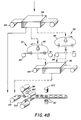
- Figs. 5-8 illustrate the construction of the conventional View -Master disk. As shown in Fig. 5, the conventional View -Master disk includes 14 film chips generally designated 10 and as shown in Fig. 6 a disk formed from six layers of laminated paper and foil 12.
- the film chips 10 representing 7 stereo image pairs 14a, b - 26a, b are made from images exposed and developed on 16mm movie film, and then cut into chips.
- the paper and foil disk 12 includes four layers of paper 28, 30, 32, and 34, and two layers of foil 36, 38.
- the paper and foil is prelaminated into two units of paper-foil-paper prior to assembly of the disk. Windows 40 are cut in the paper and foil for mounting the stereo pairs.
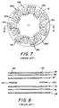
- Fig. 7 shows how the film chips are mounted in the paper and foil laminated disk 12.
- Fig. 8 is an exploded cross sectional view of a completed View -Master disk taken along line 8-8 in Fig. 7 showing how the film chips 14a, b are mounted in the windows 40 that are cut in the laminated disk. Referring back to Fig.
- one of the weak points of the conventional View -Master disk is the thin web of material 42 between the interior corners of the windows 40 in the laminated disk 12. Because this web of material 42 needs to be at least greater than some minimum dimension, the size of the stereo image for a given number of images, e.g. 14 images separated by a given stereo separation x, e.g. 65mm is limited to some maximum dimension, e.g. 10.5x11.7mm. Although a 65mm separation between the images in a stereo pair is comfortable for the average adult, a separation of 55mm to 58mm is more appropriate for a child under the age of 10. Unfortunately, if the separation is reduced from 65mm to 55mm, the webs 42 become so thin that the disk becomes too fragile for normal use.
- Fig. 9 illustrates the three degrees of freedom X, Y and ⁇ in which each of the film chips 14a and b must be precisely located. It will be appreciated from the foregoing description that the apparatus for assembling the stereo image disk must be quite complex with many moving parts. It is an object of the present invention to provide an improved construction for a stereo image disk that avoids the problems noted above. It would be desirable to be able to produce large quantities in a short time (e.g. 10 million per month) of the stereoscopic disks, for example for the advertising, toy and souvenir markets. Unfortunately, the cost of the assembly equipment is prohibitive for producing one time large batches of the elements. It is a further object of the present invention to provide a method for rapidly making large volumes of such disks.
- a stereoscopic disk including a disk of photographic film bearing a plurality of stereoscopic image pairs arranged around the circumference of the disk.
- the disk may be sandwiched between a pair of disks of opaque material defining a plurality of windows around the periphery of the opaque disks, the disks of opaque material being bonded to the disk of photographic film with the stereoscopic images located in the windows.
- the stereoscopic disk according to the present invention has the advantage of being more rugged than the prior art stereoscopic disks since the thin webs of material between the inside corners of the film chips that are required in the prior art stereoscopic disks to provide physical strength to the disks are not required.
- the disk of film material provides the physical strength and the webs of material in the opaque disks between the inside corners of the film images do not provide structural support.
- the stereoscopic disk according to the present invention has the further advantage that a child size disk having the separation of only 55mm to 58mm between stereo pairs can be constructed without decreasing the standard 10.5x11.7mm size of the images.
- the window size may be increased by approximately 20% in each direction thereby increasing the resolution of the image and allowing a reduction in magnification of the image which results in improved accommodation of different interpupillary distances.
- the stereoscopic disk according to the present invention has the further advantage of being much simpler to make than the prior art disk and therefore susceptible to rapid production in large batches.
- a stereoscopic disk is made by the steps of: providing a master stereoscopic image comprising a plurality of stereoscopic image pairs arranged in a circle; printing the master stereoscopic image onto a strip of photographic transparency film in a photographic printer; developing the stereoscopic image in the photographic transparency material; and punching a disk containing the print of the stereoscopic image out of the transparency material.
- This method has the advantage of being simpler and more cost effective than the prior art method of making the stereoscopic disk. It has the further advantage that photographic processing apparatus capable of processing enormous quantities of the transparency film is readily available, thereby avoiding the need for building special processing facilities for large production quantities of the stereoscopic disks.
- a simple stereoscopic device having a film disk with stereoscopic images arranged around the periphery of the disc, a retainer for holding the film disc, and a binocular viewer mated to the retainer for rotatably locating successive stereo image pairs on the disc in the field of view of the binocular viewer.
- the regions of the film disc around the stereoscopic images may be exposed to maximum density.
- the stereoscopic disk 50 includes a disk 52 of photographic film having a plurality of stereo image pairs 54 arranged around the periphery of the disk in the pattern well known in the art.
- the film disk 52 is sandwiched between two opaque disks 56 and 58 having windows 60 in which the stereo images 54 are positioned.
- the opaque disks 56 and 58 are preferably adhesive backed paper but may be formed from an opaque plastic sheet.
- the film disks 52 and the opaque disks 56 and 58 are laminated together to form the stereoscopic disk which closely resembles the prior art View -Master disk but as can be appreciated, is of much simpler construction.
- the series of detent slots 62 are arranged around the periphery of the disk for locating and rotating the disk in a viewer as is well known in the art.
- Titles 64 may be provided on the central region of the opaque disk 58 describing the scenes on the disk, as is well known in the art.
- Fig. 2 shows a cross section of the stereoscopic disk 50 taken along lines 2-2 in Fig. 1. Since the webs 66 of material in the opaque disk between the inside corners of the windows 60 are not required for physical integrity of the completed disk 50, they may be as narrow as desired to the point of touching at the corners of the windows, thereby allowing the images 54 of the stereoscopic disk 50 to be up to 20% larger in both the horizontal and vertical dimensions than the standard size View -Master disk with a spacing of 65mm between images in a stereo pair.
- a small "child sized" disk having a spacing of 55-58mm may be constructed having the same number and size of images as the standard size View -Master disk, thereby preserving the resolution of the images.
- One way of making the film disk 54 is shown in Fig. 3.
- a master scene 68 is prepared on a color negative film such as Eastman Color Negative, Vericolor, or Kodacolor brand film manufactured by the Eastman Kodak Company, Rochester New York.
- the left and right images in the stereo pairs are indicated as L n , R n respectively, and are arranged in a circle in the master scene 68.
- This master scene may be made for example by manually laying up a group of stereoscopic images, and photographing them in a process camera. If the stereoscopic images are transparencies, they may be placed in a mechanical holder, and used directly in a printer. Alternatively, the master scene may be generated digitally by scanning stereo pairs and producing the master scene on a graphic arts terminal.
- the master scene 68 is printed on a photographic printer (represented simply by lens 70) onto a transparency film 72 such as Eastman Color Print, Vericolor Print or Dura Clear Trans film manufactured by the Eastman Kodak Company. This method is appropriate where very large numbers of identical stereoscopic disks are to be prepared.
- Fig. 4 illustrates one example of how the stereoscopic disk 50 of the present invention may be produced.
- a series of stereoscopic images 74 produced on a photographic film strip 76 in a conventional manner are scanned in a digital film scanner 78 such as a Perkin Elmer PDS Microdensitometer or an Eikonix Model 1435 high resolution scanner, to produce digital stereo image pairs.
- the images may be produced from a "Photo CD" service available through photo dealers.
- the digital stereo images are stored in the memory of a digital image processing computer 80 and are arranged by an operator working with a keyboard 82 and CRT 84 in the desired pattern for the master scene.
- the master scene is printed out on an output film scanner 86 such a MacDonald-Detweiler Associates Fire 1000 film recorder, onto a transparency film.
- the master scene 68 is then printed a number of times in a photographic printer 88 shown schematically as a light source 90 and printing lens 92 onto a roll 94 of positive transparency film.
- a conventional step and repeat type printer is capable of producing about 4 frames per second.
- An order of magnitude higher printing speed can be achieved as illustrated by dotted lines in Fig. 4 by preparing a second generation master loop 95 containing several identical copies of the master scene arranged around a loop of transparency film.
- the master loop 95 is then repeatedly copied onto a strip of film in either a contact printer 97 or a non-contact printer 99 of the type employed for reproducing motion picture films. Avantageously, the regions of said film between images are exposed to maximum density.
- the exposed roll of film 94 is developed in a film processor 96.
- the developed roll of transparency film 94 is then laminated between strips of opaque material 98, 100 having the circular pattern of windows 60 pre-punched. Finally, the completed stereoscopic disks 50 are punched from the laminated strips by a circular punch 102.
- the resulting stereoscopic disks 50 in the standard 65mm spacing size can be used in any existing View -Master viewer. Non standard disks will require special viewers.
- Fig. 10 is an exploded perspective view of one example of such a simple stereoscopic viewer 104.
- the viewer comprises a film retaining ring 106 that can be manually rotated by means of finger levers 108 with respect to a binocular viewer body 110.
- the binocular viewer body 110 includes a pair of lens barrels 112 and 114 which contain simple lenses 116 and 118, respectively.
- the binocular viewer body 110 defines a window 120, through which a caption describing the scene in the viewer can be observed.
- the viewer body 110 may be provided with detents 121 which cooperate with a pawl 123 on the retaining ring 106 to accurately locate the stereoscopic images in the viewer.
- the film disc 122 is provided with tabs 124 having holes 126 that fit over posts 128 on retaining ring 106.
- the film disc itself may be provided with a diffuse surface on the side away from the viewing lenses 116,118.
- Fig. 11 is a cross sectional view of the stereoscopic viewer. As shown in Fig. 11, posts 128 are provided with retaining latches that snap over the edge of the viewer body 110 to hold the retaining ring to the viewer body and to retain the film disc 122 (and optionally the diffuser 130) between the retaining ring and the viewer body.
- the viewer body 110, lens barrels 112,114 and lenses 116,118 are injection molded as a single unit from clear plastic.
- the inside of lens barrels 112,114 may be painted, or paper tubes inserted in them to prevent stray light from entering the lens barrels.
- the viewer body may be injection molded from opaque plastic and lenses 116 and 118 mounted in the lens barrels.
- the stereoscopic viewer 104 may be designed for children with a spacing between images in a stereo pair of 55-58mm. Preferably seven pairs of 10.5 x 11.7mm images are provided on the periphery of the film disk 122. With this spacing, the disk can be produced from unperforated 70mm wide film as shown in Fig. 12. This is advantageous in that 70mm is a standard width for film. As illustrated in Fig. 12, one pair of stereo images 132 is placed very near the edge of the film strip 134 such that the film disk that is punched from the 70mm film strip has 2 flat spots 136 near these images. The outline of the punch used to produce the film disc is shown by dotted lines, illustrating the location of the tabs 124 on the film disk. Registration marks 138 may be provided in the printer and later sensed at the punching step to aid in the accurate location of the film strip 132 in the punch.
Landscapes
- Physics & Mathematics (AREA)
- General Physics & Mathematics (AREA)
- Stereoscopic And Panoramic Photography (AREA)
- Silver Salt Photography Or Processing Solution Therefor (AREA)
Applications Claiming Priority (2)
| Application Number | Priority Date | Filing Date | Title |
|---|---|---|---|
| US08/071,153 US5371562A (en) | 1993-06-02 | 1993-06-02 | Stereoscopic disk and viewer and method of making |
| US71153 | 1993-06-02 |
Publications (1)
| Publication Number | Publication Date |
|---|---|
| EP0628853A1 true EP0628853A1 (fr) | 1994-12-14 |
Family
ID=22099580
Family Applications (1)
| Application Number | Title | Priority Date | Filing Date |
|---|---|---|---|
| EP94420153A Withdrawn EP0628853A1 (fr) | 1993-06-02 | 1994-05-27 | Disque stéréoscopique ainsi qu'un appareil de visualisation et une méthode de production d'un tel disque |
Country Status (3)
| Country | Link |
|---|---|
| US (1) | US5371562A (fr) |
| EP (1) | EP0628853A1 (fr) |
| JP (1) | JPH0713276A (fr) |
Cited By (1)
| Publication number | Priority date | Publication date | Assignee | Title |
|---|---|---|---|---|
| US5764814A (en) * | 1996-03-22 | 1998-06-09 | Microsoft Corporation | Representation and encoding of general arbitrary shapes |
Families Citing this family (6)
| Publication number | Priority date | Publication date | Assignee | Title |
|---|---|---|---|---|
| JPH08223329A (ja) * | 1995-02-15 | 1996-08-30 | Fuji Photo Film Co Ltd | フイルム画像プリント装置 |
| US6201890B1 (en) * | 1998-12-30 | 2001-03-13 | General Electric Company | Digital-to-film radiographic image conversion |
| US6295067B1 (en) | 1999-03-12 | 2001-09-25 | Richard Dubnow | Method of manufacturing a 3D viewing disk |
| US7522174B2 (en) * | 2003-06-30 | 2009-04-21 | Canon Kabushiki Kaisha | Image processing apparatus, image processing method, program for implementing image processing method, and recording medium recording program |
| JP4323882B2 (ja) * | 2003-06-30 | 2009-09-02 | キヤノン株式会社 | 画像処理装置及び画像処理方法 |
| EP1844947B1 (fr) * | 2005-01-13 | 2010-02-10 | Nippon Paper Industries Co., Ltd. | Support d'impression thermosensible |
Citations (4)
| Publication number | Priority date | Publication date | Assignee | Title |
|---|---|---|---|---|
| GB2119940A (en) * | 1982-05-13 | 1983-11-23 | Optische Ind De Oude Delft Nv | A multiple-image printer |
| JPS5913230A (ja) * | 1982-07-15 | 1984-01-24 | Tokyo Color:Kk | 表示用写真シ−トとその製造方法および装置 |
| JPH02152388A (ja) * | 1988-12-05 | 1990-06-12 | Sharp Corp | 立体プリント装置 |
| EP0460713A2 (fr) * | 1986-05-22 | 1991-12-11 | Tyco Industries, Inc. | Appareil de visualisation stéréoscopique |
Family Cites Families (4)
| Publication number | Priority date | Publication date | Assignee | Title |
|---|---|---|---|---|
| US3772465A (en) * | 1971-06-09 | 1973-11-13 | Ass Of Motion Picture Televisi | Image modification of motion pictures |
| US4902580A (en) * | 1988-04-01 | 1990-02-20 | Ppg Industries, Inc. | Neutral reflecting coated articles with sputtered multilayer films of metal oxides |
| US5136619A (en) * | 1989-02-13 | 1992-08-04 | The United States Of America As Represented By The United States Department Of Energy | Thermal breeder fuel enrichment zoning |
| US5276478A (en) * | 1992-05-19 | 1994-01-04 | Eastman Kodak Company | Method and apparatus for optimizing depth images by adjusting print spacing |
-
1993
- 1993-06-02 US US08/071,153 patent/US5371562A/en not_active Expired - Fee Related
-
1994
- 1994-05-27 EP EP94420153A patent/EP0628853A1/fr not_active Withdrawn
- 1994-05-30 JP JP6116115A patent/JPH0713276A/ja active Pending
Patent Citations (4)
| Publication number | Priority date | Publication date | Assignee | Title |
|---|---|---|---|---|
| GB2119940A (en) * | 1982-05-13 | 1983-11-23 | Optische Ind De Oude Delft Nv | A multiple-image printer |
| JPS5913230A (ja) * | 1982-07-15 | 1984-01-24 | Tokyo Color:Kk | 表示用写真シ−トとその製造方法および装置 |
| EP0460713A2 (fr) * | 1986-05-22 | 1991-12-11 | Tyco Industries, Inc. | Appareil de visualisation stéréoscopique |
| JPH02152388A (ja) * | 1988-12-05 | 1990-06-12 | Sharp Corp | 立体プリント装置 |
Non-Patent Citations (3)
| Title |
|---|
| EASTMAN KODAK CO.: "stereo camera", RESEARCH DISCLOSURE, vol. 2244, no. 12, 10 August 1978 (1978-08-10), HAVANT GB, pages 37 - NR172109 * |
| PATENT ABSTRACTS OF JAPAN vol. 14, no. 408 (E - 0972) 4 September 1990 (1990-09-04) * |
| PATENT ABSTRACTS OF JAPAN vol. 8, no. 101 (P - 273) 12 May 1984 (1984-05-12) * |
Cited By (1)
| Publication number | Priority date | Publication date | Assignee | Title |
|---|---|---|---|---|
| US5764814A (en) * | 1996-03-22 | 1998-06-09 | Microsoft Corporation | Representation and encoding of general arbitrary shapes |
Also Published As
| Publication number | Publication date |
|---|---|
| US5371562A (en) | 1994-12-06 |
| JPH0713276A (ja) | 1995-01-17 |
Similar Documents
| Publication | Publication Date | Title |
|---|---|---|
| US4607949A (en) | Photographic print making method | |
| US4101210A (en) | Projection apparatus for stereoscopic pictures | |
| CA1042252A (fr) | Photographie stereoscopique lenticulaire a angle de projection variable | |
| US4175844A (en) | Optical imaging system | |
| EP0735420B1 (fr) | Appareil pour imprimer, stocker et recouvrir une image enregistrée | |
| EP0552805A1 (fr) | Imprimante photographique tridimensionelle et méthode | |
| EP0654701A1 (fr) | Procédé de fabrication d'une image améliorée stéréoscopique obtenu avec ledit procédé | |
| US4198147A (en) | Encoding system | |
| CA2115466A1 (fr) | Methode de developpement pour la photographie | |
| US5371562A (en) | Stereoscopic disk and viewer and method of making | |
| US4601573A (en) | Continuous photo mount | |
| EP0614118B1 (fr) | Feuille de film | |
| CA2139467A1 (fr) | Methode de production d'imprimes d'indexation | |
| US3508920A (en) | Three-dimensional pictures and method of making | |
| US5408295A (en) | Method of making stereoscopic images in a circular pattern | |
| EP0597396A1 (fr) | Imprimante à tube à rayoNS cathodiques pour photographies lenticulaires | |
| JPH10123633A (ja) | レンチキュラーレンズを用いた立体画像のための位置決め方法及び装置 | |
| US6295067B1 (en) | Method of manufacturing a 3D viewing disk | |
| US3596584A (en) | Method for converting relief photographs | |
| RU2129725C1 (ru) | Способ получения стереоскопических растровых фотографий | |
| EP1086455B1 (fr) | Bandes son numeriques compatibles pour film cinematographique 70 mm | |
| JPS60156064A (ja) | 写真材料とシ−ト状の原画とを相対的に位置決めする装置を含む写真露光装置 | |
| Meyers et al. | New advances in computer-generated barrier-strip autostereography | |
| US8237704B1 (en) | Method of manufacturing a three-dimensional viewing disk | |
| May | 16 Mm. Sound Film Dimensions |
Legal Events
| Date | Code | Title | Description |
|---|---|---|---|
| PUAI | Public reference made under article 153(3) epc to a published international application that has entered the european phase |
Free format text: ORIGINAL CODE: 0009012 |
|
| AK | Designated contracting states |
Kind code of ref document: A1 Designated state(s): DE FR GB |
|
| 17P | Request for examination filed |
Effective date: 19950516 |
|
| 17Q | First examination report despatched |
Effective date: 19961122 |
|
| STAA | Information on the status of an ep patent application or granted ep patent |
Free format text: STATUS: THE APPLICATION IS DEEMED TO BE WITHDRAWN |
|
| 18D | Application deemed to be withdrawn |
Effective date: 19970403 |